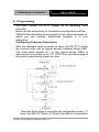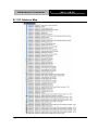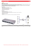
1
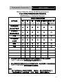
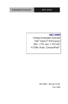
Embedded Controller
AEC-6860
AEC-6860
Fanless Embedded Controller
Intel® CoreTM 2 Duo Processor
with Gigabit Ethernet,
4 COMs, Audio, VGA,
DVI, LVDS, TV-out
AEC-6860 Manual 3rd Ed.
June 2010
Embedded Controller
AEC-6860
Copyright Notice
This document is copyrighted, 2010. All rights are reserved. The
original manufacturer reserves the right to make improvements to
the products described in this manual at any time without notice.
No part of this manual may be reproduced, copied, translated, or
transmitted in any form or by any means without the prior written
permission of the original manufacturer. Information provided in
this manual is intended to be accurate and reliable. However, the
original manufacturer assumes no responsibility for its use, or for
any infringements upon the rights of third parties that may result
from its use.
The material in this document is for product information only and is
subject to change without notice. While reasonable efforts have
been made in the preparation of this document to assure its
accuracy, AAEON assumes no liabilities resulting from errors or
omissions in this document, or from the use of the information
contained herein.
AAEON reserves the right to make changes in the product design
without notice to its users.
i
Embedded Controller
AEC-6860
Acknowledgments
•
Award is a trademark of Award Software International, Inc.
•
CompactFlash™ is a trademark of the Compact Flash
Association.
•
Intel®, Core™ 2 Duo, Pentium®, Celeron® M are trademarkes of
Intel® Corporation.
•
Microsoft Windows is a registered trademark of Microsoft
Corp.
•
PC/AT, PS/2, and VGA are trademarks of International
Business Machines Corporation.
®
All other product names or trademarks are properties of their
respective owners.
ii
Embedded Controller
AEC-6860
Packing List
Before you begin operating your PC, please make sure that the
following materials have been shipped:
z
1
AEC-6860 Embedded Controller
z
1
Keyboard & mouse cable
z
1
Phoenix Power Connector
z
2
Wallmount Brackets
z
1
Audio Cable
z
1
Screw Package
z
1
CD-ROM for manual (in PDF format) and
drivers
If any of these items should be missing or damaged, please
contact your distributor or sales representative immediately.
iii
Embedded Controller
AEC-6860
Safety & Warranty
1. Read these safety instructions carefully.
2. Keep this user's manual for later reference.
3. Disconnect this equipment from any AC outlet before cleaning. Do
not use liquid or spray detergents for cleaning. Use a damp cloth.
4. For pluggable equipment, the power outlet must be installed near
the equipment and must be easily accessible.
5. Keep this equipment away from humidity.
6. Put this equipment on a firm surface during installation. Dropping
it or letting it fall could cause damage.
7. The openings on the enclosure are for air convection. Protect the
equipment from overheating. DO NOT COVER THE OPENINGS.
8. Make sure the voltage of the power source is correct before
connecting the equipment to the power outlet.
9. Position the power cord so that people cannot step on it. Do not
place anything over the power cord.
10. All cautions and warnings on the equipment should be noted.
11. If the equipment is not used for a long time, disconnect it from the
power source to avoid damage by transient over-voltage.
12. Never pour any liquid into an opening. This could cause fire or
electrical shock.
13. Never open the equipment. For safety reasons, only qualified
service personnel should open the equipment.
14. If any of the following situations arises, get the equipment
checked by service personnel:
a.
The power cord or plug is damaged.
b.
Liquid has penetrated into the equipment.
c.
The equipment has been exposed to moisture.
iv
Embedded Controller
AEC-6860
d.
The equipment does not work well, or you cannot get it
to work according to the user’s manual.
e.
The equipment has been dropped and damaged.
f.
The equipment has obvious signs of breakage.
15. DO NOT LEAVE THIS EQUIPMENT IN AN ENVIRONMENT
WHERE THE STORAGE TEMPERATURE IS BELOW -20°C
(-4°F) OR ABOVE 60°C (140°F). IT MAY DAMAGE THE
EQUIPMENT.
FCC
This device complies with Part 15 FCC Rules.
Operation is subject to the following two
conditions: (1) this device may not cause
harmful interference, and (2) this device must
accept any interference received including
interference that may cause undesired
operation.
Caution:
There is a danger of explosion if the battery is incorrectly
replaced. Replace only with the same or equivalent type
recommended by the manufacturer. Dispose of used batteries
according to the manufacturer’s instructions and your local
government’s recycling or disposal directives.
v
Embedded Controller
AEC-6860
Below Table for China RoHS Requirements
产品中有毒有害物质或元素名称及含量
AAEON Boxer/ Industrial System
有毒有害物质或元素
部件名称
铅
汞
(Pb) (Hg)
印刷电路板
镉
六价铬 多溴联苯 多溴二苯
(Cd) (Cr(VI)) (PBB)
醚(PBDE)
×
○
○
○
○
○
×
○
○
○
○
○
×
○
○
○
○
○
×
○
○
○
○
○
硬盘
×
○
○
○
○
○
电源
×
○
○
○
○
○
及其电子组件
外部信号
连接器及线材
外壳
中央处理器
与内存
O:表示该有毒有害物质在该部件所有均质材料中的含量均在
SJ/T 11363-2006 标准规定的限量要求以下。
X:表示该有毒有害物质至少在该部件的某一均质材料中的含量超出
SJ/T 11363-2006 标准规定的限量要求。
备注:
一、此产品所标示之环保使用期限,系指在一般正常使用状况下。
二、上述部件物质中央处理器、内存、硬盘、电源为选购品。
vi
Embedded Controller
AEC-6860
Contents
Chapter 1 General Information
1.1 Introduction................................................................ 1-2
1.2 Features .................................................................... 1-4
1.3 Specifications ............................................................ 1-5
Chapter 2 Hardware Installation
2.1 Dimension ................................................................. 2-2
2.2 COM2 RI/+5V/+12V Selection (JP3)......................... 2-3
2.3 COM2 RS-232/422/485 Serial Port Connector ......... 2-4
2.4 COM1 RS-232 Serial Port Connector ....................... 2-4
2.5 LVDS Pin Definition................................................... 2-5
2.6 RAM Module Installation ........................................... 2-6
2.7 CD-ROM and 2.5” HDD Kit Installation ..................... 2-8
2.8 Dual 2.5” HDD Kit Installation ................................... 2-14
2.9 3.5” HDD Kit Installation ............................................ 2-18
2.10 Wallmount Bracket Installation................................ 2-22
Chapter 3 Award BIOS Setup
3.1 System Test and Initialization. .................................. 3-2
3.2 Award BIOS Setup .................................................... 3-3
Chapter 4 Driver Installation
4.1 Installation ................................................................. 4-3
vii
Embedded Controller
AEC-6860
Appendix A Programming The Watchdog Timer
A.1 Programming ........................................................A-2
A.2 IT8712 Watchdog Timer Initial Program ..............A-6
Appendix B I/O Information
B.1 I/O Address Map ..................................................B-2
B.2 1st MB Memory Address Map ...............................B-3
B.3 IRQ Mapping Chart ..............................................B-4
B.4 DMA Channel Assignments .................................B-4
viii
Embedded Controller
AEC-6860
Chapter
1
General
Information
Chapter 1 General Information 1- 1
Embedded Controller
AEC-6860
1.1 Introduction
Due to the growing popularity from the IPC market, the newest
Boxer series AEC-6860 has been introduced by AAEON.
Compared with the AEC-6850, it is an advanced version because it
utilizes an Intel® Core 2 Duo processor without a fan.
New Innovation for Entertainment Multimedia Domain
In this era of information explosion, the advertising of consumer
products will not be confined to the family television, but will also
spread to high-traffic public areas, like department stores, the bus,
transportation station, the supermarket etc. The advertising
marketing industry will resort to every conceivable means to
transmit product information to consumers. System integrators
will need a multifunction device to satisfy commercial needs for
such public advertising.
Being a control center, the AEC-6860 is suitable for public
multimedia entertainment services. Equipped with a high efficiency
heat conduction mechanism.
The AEC-6860 is compact in size but has attractive and flexible
extension capabilities such as 4 USB2.0 ports, VGA, TV-out, DVI,
Audio, 4 COM ports.
Chapter 1 General Information 1-2
Embedded Controller
AEC-6860
Stable Design for Rugged Environment
The AEC-6860 is designed for rugged environments due to the
following reasons; first, it can withstand tough vibration testing up to
5G rms. With the anti-vibration hard drive device option, the
AEC-6860 can be used in high vibration environments. In addition,
the AEC-6860 offers low power consumption system that while
operating in ambient temperatures ranging from -15° to 60°C.
The AEC-6860 is a standalone high performance controller
designed for long-life operation and with high reliability. It can
replace traditional methods and become the mainstream
controller for the multimedia entertainment market.
Chapter 1 General Information 1- 3
Embedded Controller
AEC-6860
1.2 Features
•
Fanless Design with Intel® Core 2 Duo Processor
•
VGA, DVI, LVDS, S-Video Output.
•
4 COMs, 4 USB 2.0, Single GbE (RJ-45)
•
Supports SATA Hard Disk Drive
Chapter 1 General Information 1-4
Embedded Controller
AEC-6860
1.3 Specifications
System
•
CPU:
Intel® Core 2 Duo
Processor up to 1.6GHz
(Optional Celeron® M 400
1.86GHz)
•
Construction:
Rugged Aluminum Alloy
chassis
•
System Memory:
DDRII 533/667 RAM
SODIMM x 1, Max. 2GB
•
VGA:
DB-15 VGA connector
•
Keyboard/Mouse:
PS/2 Keyboard & Mouse
by extension cable
•
Ethernet:
Single Gigabit Ethernet
RJ-45 connector x 1
•
SSD:
Internal Type II
CompactFlash™ slot x 1
•
Display Interface:
DVI, LVDS, S-Video
•
Device Bay (Optional):
CD-ROM & 2.5”HDD
(SATA/IDE) Kit, 2 x 2.5”
HDD(SATA/IDE) Kit, 3.5”
HDD(SATA/IDE) Kit
•
Serial Port:
3 x RS-232 (COM1,3,4),
1 x RS-232/422/485
Chapter 1 General Information 1- 5
Embedded Controller
AEC-6860
(COM2)
•
Audio:
MIC / Line In / Line Out (by
extension cable)
•
USB:
4 USB 2.0 ports
•
Watchdog Timer:
Generate a time-out
System reset, setting via
software
•
Power Supply:
1. DC input: Internal DC to
DC converter (Default); Input
range: DC 9V/12A~30V/3.6A
2. AC input: External power
adapter (Optional); Input
range: AC 100~240V @
50~60Hz
•
System Control:
Power on / off switch x 1
Reset button x 1
•
Indicator:
Power LED x 1
HDD active LED x 1
•
OS Support:
Windows® XP, Windows®
2000
Mechanical and Environmental
•
Construction:
Rugged Aluminum Alloy
chassis
•
Color:
Dark Blue
•
Mounting:
Wallmount, Desktop
Chapter 1 General Information 1-6
Embedded Controller
•
Dimension:
AEC-6860
13.22” (W) x 11.57” (H) x
10.24” (D) (336mm x 294mm
x 260mm)
•
Net Weight:
5.57lb (2.53kg)
•
Gross Weight:
10.34lb (4.7kg)
•
Operation Temperature: 5°F ~ 140°F (-15°C ~
55°C) – Core 2 Duo
1.67GHz/CFD; 32°F ~
122°F (0°C ~ 50°C) –Core
2 Duo 1.6GHz/Automotive
HDD
•
Storage Humidity:
5~95% @ 40°C,
non-condensing
•
Vibration:
5 g rms / 5~500Hz /
random operation (CFD)
1 g / 5~500Hz / random
operation (HDD)
•
Shock:
100g peak acceleration
(11 msec. duration)
20g peak acceleration (11
msec. duration) (HDD)
•
EMC:
CE/FCC class A
Chapter 1 General Information 1- 7
Embedded Controller
Front Side
Rear Side
Chapter 1 General Information 1-8
AEC-6860
Embedded Controller
AEC-6860
Chapter
2
Hardware
Installation
Chapter 2 Hardware Installation 2-1
Embedded Controller
2.1 Dimension
Chapter 2 Hardware Installation 2 - 2
AEC-6860
Embedded Controller
AEC-6860
2.2 COM2 RI/+5V/+12V Selection (JP3)
JP3
Function
1-2
+12V
3-4
+5V
5-6
RI
Chapter 2 Hardware Installation 2 - 3
Embedded Controller
AEC-6860
2.3 COM2 RS-232/422/485 Serial Port Connector
Different devices implement the RS-232/422/485 standard in
different ways. If you are having problems with a serial device, be
sure to check the pin assignments below for the connector.
Pin
Signal
Pin
Signal
1
DCD (422TXD-/485DATA-)
2
RXD (422RXD+)
3
TXD (422TXD+/485DATA+)
4
DTR (422RXD-)
5
GND
6
DSR
7
RTS
8
CTS
9
RI
10
N.C.
2.4 COM1 RS-232 Serial Port Connector
Pin
Signal
Pin
Signal
1
DCD
2
RXD
3
TXD
4
DTR
5
GND
6
DSR
7
RTS
8
CTS
9
RI
10
N.C.
Chapter 2 Hardware Installation 2 - 4
Embedded Controller
AEC-6860
2.5 LVDS Pin Definition
Pin
Signal
Pin
Signal
1
BKLEN
16
TXUCLK
2
BKLCTL
17
SDATA
3
VCC
18
SCLK
4
GND
19
TXLCLK#
5
TXL1#
20
TXLCLK
6
TXL1
21
TXL0#
7
VCC
22
TXL0
8
GND
23
TXL2#
9
TXU0#
24
TXL2
10
TXU0
25
NC
11
TXU1#
26
NC
12
TXU1
27
VCC
13
TXU2#
28
GND
14
TXU2
29
NC
15
TXUCLK#
30
NC
Chapter 2 Hardware Installation 2 - 5
Embedded Controller
AEC-6860
2.6 RAM Module Installation
Step 1: Take off the lid from the bottom of the chassis by loosening the
screws.
Chapter 2 Hardware Installation 2 - 6
Embedded Controller
AEC-6860
Step 2: Cover the chips with a thermal pad
Chapter 2 Hardware Installation 2 - 7
Embedded Controller
AEC-6860
Step 3: Place the lid back on and lock with screws.
2.7 CD-ROM and 2.5” HDD Kit Installation
CD-ROM and 2.5” HDD Kit Combination
Step 1: Get the disk bracket ready.
Chapter 2 Hardware Installation 2 - 8
Embedded Controller
AEC-6860
Step 2: Fasten the CD-ROM to the disk bracket with screws.
Step 3: Fasten the Riser Card and the CD-ROM with screws.
Riser Card
Step 4: Fasten the 2.5” HDD module to the disk bracket with screws.
Chapter 2 Hardware Installation 2 - 9
Embedded Controller
AEC-6860
Step 5: Insert the SATA cable and IDE cable into the slots on the Riser
Card and the 2.5” HDD module.
IDE Cable
Chapter 2 Hardware Installation 2 - 10
Embedded Controller
AEC-6860
Step 6: Place the CD-ROM and HDD kit into the suitable plate and then
reverse it. Screw the CD-ROM and HDD kit to the plate.
Cable Insertion
Step 1: Open the HDD cover by loosening the screws on the bottom of
the chassis.
Chapter 2 Hardware Installation 2 - 11
Embedded Controller
AEC-6860
Step 2: Insert the other side of IDE cable into the slot on the bottom of
the chassis.
IDE Cable
Chapter 2 Hardware Installation 2 - 12
Embedded Controller
AEC-6860
Step 3: Combine the chassis with the CD-ROM and 2.5” HDD kit plate.
Then lock with screws.
Chapter 2 Hardware Installation 2 - 13
Embedded Controller
AEC-6860
2.8 Dual 2.5” HDD Kit Installation
HDD Kit Combination
Step 1: Get the bracket ready. Attach the rubber shock absorbers with
the bracket as illustration shown below.
Step 2: Fasten the first HDD module to the bracket with screws.
Step 3: Fasten the second HDD module to the bracket with screws.
Chapter 2 Hardware Installation 2 - 14
Embedded Controller
AEC-6860
Step 4: Insert the HDD cable into the slot on the HDD module.
SATA HDD Cable
Power Cable
Step 5: Place the HDD kit into the HDD kit housing and then screw the
HDD kit onto the HDD kit housing.
Chapter 2 Hardware Installation 2 - 15
Embedded Controller
AEC-6860
Cable Insertion
Step 1: Open the HDD cover by loosening the screws on the bottom of
the chassis.
Step 2: Insert the other side of HDD cable into the slot on the bottom of
the chassis.
IDE Cable
SATA HDD
Cable/ EXT
Power Cable
Chapter 2 Hardware Installation 2 - 16
Embedded Controller
AEC-6860
Step 3: Combine the chassis with the HDD kit housing and then lock with
screws.
Chapter 2 Hardware Installation 2 - 17
Embedded Controller
AEC-6860
2.9 3.5” HDD Kit Installation
HDD Kit Combination
Step 1: Get the HDD module ready. Insert power cable and HDD cable
into the slots on the HDD module.
SATA HDD Cable
EXT Power Cable
Step 2: Get the bracket ready.
Step 3: Attach the rubber shock absorbers to the bracket as illustration
shown below.
Chapter 2 Hardware Installation 2 - 18
Embedded Controller
AEC-6860
Step 4: Fasten the HDD module to the bracket with screws.
Step 5: Get the screws ready, by matching them up with a washer.
Meanwhile, place the HDD kit into the HDD kit housing and then screw
the HDD kit to the HDD kit housing.
Magnificent
Chapter 2 Hardware Installation 2 - 19
Embedded Controller
AEC-6860
Cable Insertion
Step 1: Open the HDD cover by loosening the screws on the bottom of
the chassis.
Step 2: Insert the other side of HDD cable and power cable into the slots
on the bottom of the chassis.
SATA HDD
Cable/ EXT
Power Cable
Chapter 2 Hardware Installation 2 - 20
Embedded Controller
AEC-6860
Step 3: Combine the chassis with the HDD kit housing and then lock with
screws.
Chapter 2 Hardware Installation 2 - 21
Embedded Controller
AEC-6860
2.10 Wallmount Bracket Installation
Fasten the brackets with the appropriate screws.
Chapter 2 Hardware Installation 2 - 22
Embedded Controller
AEC-6860
Chapter
3
Award
BIOS Setup
Chapter 3 Award BIOS Setup 3-1
Embedded Controller
AEC-6860
3.1 System Test and Initialization
These routines test and initialize board hardware. If the routines
encounter an error during the tests, you will either hear a few
short beeps or see an error message on the screen. There are
two kinds of errors: fatal and non-fatal. The system can usually
continue the boot up sequence with non-fatal errors. Non-fatal
error messages usually appear on the screen along with the
following instructions:
Press <F1> to RESUME
Write down the message and press the F1 key to continue the
boot up sequence.
System configuration verification
These routines check the current system configuration against
the values stored in the CMOS memory. If they do not match,
the program outputs an error message. You will then need to
run the BIOS setup program to set the configuration information
in memory.
There are three situations in which you will need to change the
CMOS settings:
1. You are starting your system for the first time
2. You have changed the hardware attached to your system
3. The CMOS memory has lost power and the configuration
information has been erased.
The AEC-6860 CMOS memory has an integral lithium battery
backup for data retention. However, you will need to replace the
complete unit when it finally runs down.
Chapter 3 Award BIOS Setup 3-2
Embedded Controller
AEC-6860
3.2 Award BIOS Setup
Awards BIOS ROM has a built-in Setup program that allows
users to modify the basic system configuration. This type of
information is stored in battery-backed CMOS RAM so that it
retains the Setup information when the power is turned off.
Entering Setup
Power on the computer and press <Del> immediately. This will
allow you to enter Setup.
Standard CMOS Features
Use this menu for basic system configuration. (Date, time, IDE,
etc.)
Advanced BIOS Features
Use this menu to set the advanced features available on your
system.
Advanced Chipset Features
Use this menu to change the values in the chipset registers and
optimize your system performance.
Chapter 3 Award BIOS Setup 3-3
Embedded Controller
AEC-6860
Integrated Peripherals
Use this menu to specify your settings for integrated
peripherals. (Primary slave, secondary slave, keyboard, mouse
etc.)
Power Management Setup
Use this menu to specify your settings for power management.
(HDD power down, power on by ring, KB wake up, etc.)
PnP/PCI Configurations
This entry appears if your system supports PnP/PCI.
PC Health Status
This menu allows you to set the shutdown temperature for your
system.
Frequency/Voltage Control
Use this menu to specify your settings for auto detect
DIMM/PCI clock and spread spectrum.
Load Fail-Safe Defaults
Use this menu to load the BIOS default values for the
minimal/stable performance for your system to operate.
Load Optimized Defaults
Use this menu to load the BIOS default values that are factory
settings for optimal performance system operations. While
AWARD has designated the custom BIOS to maximize
performance, the factory has the right to change these defaults
to meet their needs.
Set Supervisor/User Password
Use this menu to set Supervisor/User Passwords.
Chapter 3 Award BIOS Setup 3-4
Embedded Controller
AEC-6860
Save and Exit Setup
Save CMOS value changes to CMOS and exit setup.
Exit Without Saving
Abandon all CMOS value changes and exit setup.
You can refer to the "AAEON BIOS Item Description.pdf"
file in the CD for the meaning of each setting in this
chapter.
Chapter 3 Award BIOS Setup 3-5
Embedded Controller
AEC-6860
Chapter
4
Driver
Installation
Chapter 4 Driver Installation 4 - 1
Embedded Controller
AEC-6860
The AEC-6860 comes with a CD-ROM that contains all
drivers and utilities that meet your needs.
Follow the sequence below to install the drivers:
Step 1 – Install Intel INF Driver
Step 2 – Install Intel VGA Driver
Step 3 – Install Intel LAN Driver
Step 4 – Install Realtek Audio Driver
Step 5 – Install Sil3132 SATA Driver
USB 2.0 Drivers are available for download using Windows
Update for both Windows XP and Windows 2000. For
additional information regarding USB 2.0 support in Windows
XP
and
Windows
2000,
please
visit
www.microsoft.com/hwdev/usb/.
Please read instructions below for further detailed
installations.
Chapter 4 Driver Installation 4 - 2
Embedded Controller
AEC-6860
4.1 Installation
Insert the AEC-6860 CD-ROM into the CD-ROM Drive. And install
the drivers from Step 1 to Step 5 in order.
Step 1 – Install Intel INF Driver
1. Click on the Step 1-Intel inf Driver folder and then
double click on the infinst_autol.exe
2. Follow the instructions that the window shows you
3. The system will help you install the driver automatically
Step 2 – Install Intel VGA Driver
1. Click on the Step 2- Intel VGA Driver folder and select
the OS folder your system is
2. Double click on the .exe located in each OS folder
3. Follow the instructions that the window shows you
4. The system will help you install the driver automatically
Note: For preventing from display resolution issues occurred on
different VGA displays, AAEON recommends you to install the driver
(Version 6.14.10.4436) in the CD-ROM.
Step 3 – Install Intel LAN Driver
1. Click on the Step 3-Intel LAN Driver folder and select
the OS folder your system is
2. Double click on the .exe file located in each OS folder
3. Follow the instructions that the window shows you
4. The system will help you install the driver automatically
Chapter 4 Drivers Installation 4 - 3
Embedded Controller
AEC-6860
Step 4 – Install Realtek Audio Driver
1. Click on the Step 4-Realtek Audio Driver folder and
select the OS folder your system is
2. Double click on the .exe file located in each OS folder
3. Follow the instructions that the window shows you
4. The system will help you install the driver automatically
Step 5 – Install Sil3132 SATA Driver
Please follow the application note to install the Step 5 - Sil3132
SATA Driver
Application Note:
Windows Operating System cannot recognize the driver of chip
Sil3132 and treat it as a third-part driver. Please follow the steps
below to install the driver with the Operating System.
1. Creating a Drive Disk: copy the SATA driver from AAEON CD
to floppy disk before install the OS
A.
Click on Step 5 - Sil3132 SATA Driver
B.
Click on SiI 3132 BASE Driver (For_BIOS_7.3.13)
C.
Click on SiI 3132 32-bit Windows BASE Driver
v1.0.19.0(For_BIOS_7.3.13)
D.
Copy all the files to the USB Floppy Disk
E.
Driver disk done
2. Insert your Windows CD, and then restart the computer
3. Follow the on-screen instructions to begin the Windows
installation.
4. When prompted to install a third-party driver, press F6.
Note: When F6 is actived, a prompt appears at the bottom of the
Chapter 4 Driver Installation 4 - 4
Embedded Controller
AEC-6860
screen for only 5 seconds.
If you did not press F6 in time, please restart your computer.
5. Insert the driver disk, and then wait until you are prompted to
install a driver.
6. Press “S” to specify the driver is on a floppy disk, and then
press “Enter.”
7. The computer reads the disk
8. When the SATA driver has been found, press “Enter.”
Chapter 4 Drivers Installation 4 - 5
Embedded Controller
AEC-6860
9. Follow the on-screen instructions to complete the installation.
After finish installing OS, you have to install Silicon Raid
Management Utility.
Setup RAID Management
A. Click on Step 5 - Sil3132 SATA Driver and select the folder
of SiI 3132 32 & 64-bit Windows SATARAID5
Management Utility(For_BIOS_7.3.13)
B. Double click on 3132-W-I32-R_1552.exe
C. Follow the instructions that the window shows
D. The system will help you install the driver automatically
Chapter 4 Driver Installation 4 - 6
Embedded Controller
AEC-6860
Appendix
A
Programming the
Watchdog Timer
Appendix A Programming the Watchdog Timer A-1
Embedded Controller
AEC-6860
A.1 Programming
AEC-6860 utilizes ITE 8712 chipset as its watchdog timer
controller.
Below are the procedures to complete its configuration and the
AAEON intial watchdog timer program is also attached based on
which you can develop customized program to fit your
application.
Configuring Sequence Description
After the hardware reset or power-on reset, the ITE 8712 enters
the normal mode with all logical devices disabled except KBC.
The initial state (enable bit ) of this logical device (KBC) is
determined by the state of pin 121 (DTR1#) at the falling edge of
the system reset during power-on reset.
There are three steps to complete the configuration setup: (1)
Enter the MB PnP Mode; (2) Modify the data of configuration
Appendix A Programming the Watchdog Timer A-2
Embedded Controller
AEC-6860
registers; (3) Exit the MB PnP Mode. Undesired result may
occur if the MB PnP Mode is not exited normally.
(1) Enter the MB PnP Mode
To enter the MB PnP Mode, four special I/O write operations
are to be performed during Wait for Key state. To ensure the
initial state of the key-check logic, it is necessary to perform
four write operations to the Special Address port (2EH). Two
different enter keys are provided to select configuration ports
(2Eh/2Fh) of the next step.
(2) Modify the Data of the Registers
All configuration registers can be accessed after entering the
MB PnP Mode. Before accessing a selected register, the
content of Index 07h must be changed to the LDN to which
the register belongs, except some Global registers.
(3) Exit the MB PnP Mode
Set bit 1 of the configure control register (Index=02h) to 1 to
exit the MB PnP Mode.
Appendix A Programming the Watchdog Timer A-3
Embedded Controller
AEC-6860
WatchDog Timer Configuration Registers
Configure Control (Index=02h)
This register is write only. Its values are not sticky; that is to
say, a hardware reset will automatically clear the bits, and
does not require the software to clear them.
Appendix A Programming the Watchdog Timer A-4
Embedded Controller
AEC-6860
WatchDog Timer Control Register (Index=71h, Default=00h)
WatchDog Timer Configuration Register (Index=72h,
Default=00h)
WatchDog Timer Time-out Value Register (Index=73h,
Default=00h)
Appendix A Programming the Watchdog Timer A-5
Embedded Controller
AEC-6860
A.2 IT8712 Watchdog Timer Initial Program
.MODEL SMALL
.CODE
Main:
CALL Enter_Configuration_mode
CALL Check_Chip
mov cl, 7
call Set_Logic_Device
;time setting
mov cl, 10 ; 10 Sec
dec al
Watch_Dog_Setting:
;Timer setting
mov al, cl
mov cl, 73h
call Superio_Set_Reg
;Clear by keyboard or mouse interrupt
mov al, 0f0h
mov cl, 71h
call Superio_Set_Reg
;unit is second.
mov al, 0C0H
mov cl, 72h
call Superio_Set_Reg
Appendix A Programming the Watchdog Timer A-6
Embedded Controller
AEC-6860
; game port enable
mov cl, 9
call Set_Logic_Device
Initial_OK:
CALL Exit_Configuration_mode
MOV AH,4Ch
INT 21h
Enter_Configuration_Mode PROC NEAR
MOV SI,WORD PTR CS:[Offset Cfg_Port]
MOV DX,02Eh
MOV CX,04h
Init_1:
MOV AL,BYTE PTR CS:[SI]
OUT DX,AL
INC SI
LOOP Init_1
RET
Enter_Configuration_Mode ENDP
Exit_Configuration_Mode PROC NEAR
MOV AX,0202h
CALL Write_Configuration_Data
Appendix A Programming the Watchdog Timer A-7
Embedded Controller
AEC-6860
RET
Exit_Configuration_Mode ENDP
Check_Chip PROC NEAR
MOV AL,20h
CALL Read_Configuration_Data
CMP AL,87h
JNE Not_Initial
MOV AL,21h
CALL Read_Configuration_Data
CMP AL,12h
JNE Not_Initial
Need_Initial:
STC
RET
Not_Initial:
CLC
RET
Check_Chip ENDP
Read_Configuration_Data PROC NEAR
MOV DX,WORD PTR CS:[Cfg_Port+04h]
OUT DX,AL
Appendix A Programming the Watchdog Timer A-8
Embedded Controller
AEC-6860
MOV DX,WORD PTR CS:[Cfg_Port+06h]
IN AL,DX
RET
Read_Configuration_Data ENDP
Write_Configuration_Data PROC NEAR
MOV DX,WORD PTR CS:[Cfg_Port+04h]
OUT DX,AL
XCHG AL,AH
MOV DX,WORD PTR CS:[Cfg_Port+06h]
OUT DX,AL
RET
Write_Configuration_Data ENDP
Superio_Set_Reg proc near
push ax
MOV DX,WORD PTR CS:[Cfg_Port+04h]
mov al,cl
out dx,al
pop ax
inc dx
out dx,al
ret
Superio_Set_Reg endp.Set_Logic_Device proc near
Set_Logic_Device proc near
Appendix A Programming the Watchdog Timer A-9
Embedded Controller
AEC-6860
push ax
push cx
xchg al,cl
mov cl,07h
call Superio_Set_Reg
pop cx
pop ax
ret
Set_Logic_Device endp
;Select 02Eh->Index Port, 02Fh->Data Port
Cfg_Port DB 087h,001h,055h,055h
DW 02Eh,02Fh
END Main
Note: Interrupt level mapping
0Fh-Dh: not valid
0Ch: IRQ12
.
.
03h: IRQ3
02h: not valid
01h: IRQ1
00h: no interrupt selected
Appendix A Programming the Watchdog Timer A-10
Embedded Controller
AEC-6860
Appendix
B
I/O Information
Appendix B I/O Information B-1
Embedded Controller
B.1 I/O Address Map
Appendix B I/O Information B-2
AEC-6860
Embedded Controller
AEC-6860
B.2 1st MB Memory Address Map
Appendix B I/O Informaion B-3
Embedded Controller
B.3 IRQ Mapping Chart
B.4 DMA Channel Assignments
Appendix B I/O Information B-4
AEC-6860