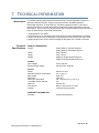
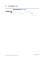
1
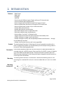
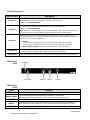
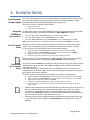
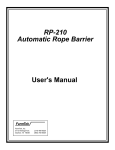
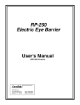
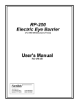
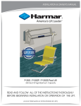
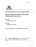
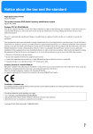
Moving Head Controller 2.0 User Manual JPC Lighting Page 1 of 20 Moving Head Controller 2.0 Manual Rev1 Table of contents: 1. BEFORE YOU BEGIN ________________________________________________________ 3 2. INTRODUCTION ___________________________________________________________ 5 3. SETUP__________________________________________________________________ 10 4. RUNNING MODE _________________________________________________________ 11 5. PROGRAMMING _________________________________________________________ 12 6. PLAYBACK ______________________________________________________________ 18 7. TECHNICAL INFORMATION _________________________________________________ 19 8. CONTACT US ____________________________________________________________ 20 Page 2 of 20 Moving Head Controller 2.0 Manual Rev1 1. BEFORE YOU BEGIN What Is Included · 1x Moving Head Controller V2.0 · 1x External Power Supply · 1x Hard Polymer traveling Case · 2x Mounting Brackets · 9x 10-32 x 1/2in Screws · 2x Extra slider-knobs · 1x A-B USB Cable Unpacking Carefully unpack the Moving Head Controller 2.0 and check that all the parts are in the Instructions package, and are in good condition. Claims If the box, or any of the contents, appear damaged from shipping, save all the packaging and file a claim with the carrier immediately. Failure to report damage to the carrier immediately, or failure to save all the packaging, can invalidate a claim. For other issues, such as missing components or parts, damage not related to shipping, or concealed damage, file a claim with JPC Lighting within 7 days of delivery. Conventions Symbols Convention 1—512 50 to 60 “15” Settings Menu > Settings <Enter> Convention Meaning A range of values A set of values Information shown on the display A menu option A sequence of menu options A button Meaning Critical information. Ignoring it can cause malfunction, damage the product, or harm the operator. Important information. Ignoring it can cause the product to malfunction. Useful information. Disclaimer The information and specifications contained in this User Manual are subject to change without notice. JPC Lighting® assumes no responsibility or liability for any errors or omissions, and reserves the right to revise or recreate this manual at any time. The latest version of this manual can be downloaded from http://www.JPClighting.com/ © Copyright 2014 JPC Lighting®. All rights reserved. Page 3 of 20 Moving Head Controller 2.0 Manual Rev1 Product at a Glance Use on Dimmer DMX (In and Out) Outdoor Use Auto-Ranging Power Supply Sound-Activated Firmware Upgradable User-Serviceable USB connection Replaceable Fuse Stackable (Daisy-chain) Safety Notes These notes include important information about the mounting, use, and maintenance of this product. Read these notes before using the product. · Always connect the product to a grounded circuit to avoid the risk of electrocution. · Make sure the power cord is not crimped or damaged. · Never disconnect the product from the power source by pulling or tugging on the cord. · If mounting the product overhead, always secure it using a safety cable. · Make sure there are no flammable materials close to the product when it is operating. · The product is for indoor use only! · Do not expose the product to rain or moisture. · Make sure the voltage of the power source used for the product is within the range stated on the label or on rear panel of the product. · Never connect the product to a dimmer or a rheostat. · Always install the product in a location with adequate ventilation. · Do not operate the product in an ambient temperature higher than 45 °C · Always carry the product by its mounting sides. · In the event of a serious operating problem, stop using the product immediately. · Never try to repair the product. Repairs carried out by untrained people can lead to damage or malfunction. · If repairs are required, contact the nearest authorized technical assistance center. Contact Us for more information. Keep this User Manual for future reference. If you sell the product to another user, be sure to give this manual to the next owner. Page 4 of 20 Moving Head Controller 2.0 Manual Rev1 2. INTRODUCTION Features · DMX Output · DMX Input · USB Input · JOYSTICK · Controls up to 6 different types of lights with up to 20 channels each · Controls multiple lights simultaneously · Passes through up to 512 DMX channels from input to output · Stores and plays back 160 chases in 60 banks of 255 scenes each · Stores and plays back 9 shows of up to 160 chases total · Accepts fader customizations · Accepts light libraries customizations · Plays back multiple chases in sequential order · Plays back multiple shows simultaneously · Controls lights “on the fly” in Playback mode · Triggers chases and scenes with preset transition and standby times · Accepts USB input to trigger scenes and chases · Accepts USB input to store, edit and upload parameters and functions the provided GUI interface · Accepts new firmware versions and is user upgradable through Product The moving Head Controller 2.0 (the board) is a small, powerful controller with a built-in Joystick that enables it to simultaneously control multiple moving heads to be used in Follow-Spotting applications. Description It has several playback modes and can control up to 512 DMX channels which are accessed using the <LIGHTS> buttons. Each one of the 6 <LIGHTS > button is linked to up-to 20 predetermined DMX channels. These 20 channels are broken down into different groups allowing 13 of the 14 physical faders alongside internal functions to control up to the 20 channels. Mounting The moving Head Controller 2.0 comes with 2 accessories Mounting Ears for rack mounting into a standard 19-inch rack. It also has rubber feet so it can sit on a table top. Mounting Accessories Page 5 of 20 Moving Head Controller 2.0 Manual Rev1 Wireless D-Fi™ Connectivity Programming Concepts The Moving Head Controller 2.0 can be connected to a wireless frequency to send DMX signals to D-Fi™ compatible products, eliminating the need for long DMX cables. The moving Head Controller 2.0 board must be within 300 ft. of the other D-Fi™ products and where there are no significant obstructions, such as concrete walls or large solid metal structures. The moving Head Controller 2.0 uses DMX addressing and values to control products. Looks are created by using the faders to send DMX values to the products. The looks are saved into scenes and the scenes are saved as steps into chases. The scenes and chases are played back as shows at different speeds and with different types of triggers. Looks are created whenever the user is manipulating products. The products are selected with the <Light-x> buttons. The Joystick and faders are moved to control the products and create looks. Then the looks are saved as scenes with the <Show-x> buttons, and the scenes are saved to steps in chases with additional scenes or looks on the same <Show-x> button. The chases are played back in Show Playback mode. Timing of playback is set with the Transition and Standby times. Looks can be created in playback mode. Page 6 of 20 Moving Head Controller 2.0 Manual Rev1 Panel Overviews The Moving Head Controller 2.0 is laid out with the LCD display to the top left, the <Light-x> buttons in the top-center, the DMX faders in the lower left, the <Show-x> buttons on the top right, the Joystick on the lower right and the <control> on the right. The back panel of the board has the ports and the power connection. For more information about the rear panel, See the Back Panel View Front Panel View Front Panel The front panel controls provide access to the Moving Head Controller 2.0 programming and Controls playback operations. The LCD display and the indicator LEDs provide information about the current operations, programming and selections. The LCD display shows different types of information in Program mode and Playback mode. The fixture button LEDs indicate when certain functions, programs and lights are selected. The Joystick allows for controlling the PAN/TILT on products for aiming the beam. Page 7 of 20 Moving Head Controller 2.0 Manual Rev1 Control Descriptions Description Button or Fader Buttons that select lights to control and set the default DMX addresses of the channel faders and Joystick. The corresponding LEDs indicate when a light ON/OFF and when is selected. Light-(1..6) <Select-ON/OFF> Light-(1..6) <Pan-Tilt/(X,Y,Z)> LED OFF = light Lamp is OFF unless Shows take control. If no show controls it then DMX-in does. LED ON = light Lamp is ON, channel Faders and Joystick take control if active or same as active. LED linking = light is selected, or active, the Faders and Joystick controls the light. Note: These buttons are inclusive. Pressing one, then another, selects both lights. To deselect a light, press it again and make sure the LED indicator is off. Buttons that select the working mode for the lights to control with the Joystick, either by direct control of the PAN and TILT movements or indirect control by means of a 3D mapping of the floor for Follow-Spotting. The corresponding LEDs indicate which mode the light is set to. LED ON = Follow-Spot, the light will aim to the (X,Y) coordinates on the floor. LED OFF = PAN/TILT, The Joystick controls the PAN and TILT directly, only on the active light. Menu Buttons to enter into the Light-Parameter and the Library-Edit programming modes. Light-(1..6) <…Setup> Push-Hold for 3 seconds to enter Light- Parameter programming mode (LED blinks one time) Push-Hold for 5 seconds to enter Library-Edit programming mode (LED blinks Two times) Note: To exit the menus out of Programming mode, Push-Hold <Aux/Exit> for 5 seconds. Buttons that save a Look in permanent memory to be recalled at a later time. Light-(1..6) <…Save/Recall> Push-Hold for 3 seconds to save the Look (all 6 lights, LED blinks one time) Push-Hold for 5 seconds to recall the Look (all 6 lights, LED blinks two times) Note: Unlike a Hot-Cue, All six lights are affected whether they were ON or OFF. Buttons that recall a Hot-Cue or turn ON and OFF a Show for playback. Show-(1..9) <ON-OFF> Show-(1..9) <…Prog> If the Show has only one saved Chase or Step; the show Button becomes a Hot-Cue instead. LED ON = The show is active and chases are triggered accordingly, only to lights that are OFF. LED OFF = The show is inactive. Note: These buttons are inclusive. Pressing one, then another recalls both shows at the same time, lower number takes precedence on a light if those lights belong to multiple shows. To deselect a show, press it again and make sure the LED indicator is off. Shows only take control of lights that are not ON. Buttons to quickly add new Chases (Looks) to the Show, and to enter into the Show-Edit programming modes. Push-Hold for 3 seconds to save current Look as a new Chase in the Show (LED blinks one time) Push-Hold for 5 seconds to enter Show-Edit programming mode (LED blinks two times) Note: To exit the menus out of Programming mode, Push-Hold <Aux/Exit> for 5 seconds. <Blackout> Toggle button that stops all DMX transmission. Makes the lights go black. LED ON = Blackout mode is active acting as a DMX pass-through for signals in the DMX input. LED OFF = Blackout mode is not active and the board is sending out its own DMX signals. <Aux/Exit> Auxiliary Button for aiding when in programming or editing modes <Enter> Auxiliary Button for aiding when in programming or editing modes. <Slide 1><Slide12> Customizable channel faders that send DMX values to the products, one channel per slider. Used in conjunction with: Light (1..6) <Select-ON/OFF> Page 8 of 20 Moving Head Controller 2.0 Manual Rev1 Control Descriptions Button or Fader Description <Dimmer> Customizable channel fader that sends DMX values to the products, This slider should be dedicated to the Dimmer channel whenever applicable. Used in conjunction with: Light (1..6) <Select-ON/OFF> Specialty not customizable channel Fader that it is used in conjunction with: <Azimuth> Light (1..6) <Select-ON/OFF> Note: This Father is used whit lights that are set in Follow-Spot mode. It elevates the point where the beams meet above the floor adding an offset to facilitate illuminating tall subjects. Multipurpose Joystick that controls the PAN/Tilt on Light Products, the (X,Y) coordinated for a Follow-Spot application and navigates through and stepping through all the different menus to edit parameters, save and recall programs, etc. <Joystick> Run Mode: - If active Light is in Follow-Spot mode, it controls the (X,Y) coordinates of the Spot. - If active Light is in PAN/TILT mode, it controls the Pan and Tilt angles of that Light. Programming/Editing mode: Navigates through Menus and changes parameters. LCD Display LCD Display that shows various types of information about current modes, selections and whether it is in Run, Program or Playback mode among other relevant and useful data. Naming Pads Convenient location to add customized naming to the Channel Faders for easy and quick access. Back Panel View Back Panel Ports Port DC Power In Power Switch DMX Out DMX In USB Port Function External PSU port that connects to the power source. Toggle switch that turns The Moving Head Controller 2.0 ON and OFF. Note: The Moving Head Controller 2.0 use a negative pin 2 and positive pin 3. 3-pin DMX port for connecting to the products. 3-pin DMX port for connecting to other DMX Controllers that support up to 512 DMX ch. Note: The Moving Head Controller 2.0 use a negative pin 2 (D-) and positive pin 3 (D+). Port for connecting to a PC. Page 9 of 20 Moving Head Controller 2.0 Manual Rev1 3. SETUP AC Power The Moving Head Controller 2.0 comes with an auto-ranging external power supply, that works with an input voltage range of 100 to 240 Vac, 50/60 Hz. The controller runs on 6 Vdc to 12 Vdc at 500 mA. Before turning on the power, make sure the line voltage is within the range of accepted voltages as listed on the label affixed to the product or as described in Technical Specifications in this document. The listed rating indicates average current draw under normal conditions. Mounting Setting Up The Board DMX Cabling Never connect the board to a rheostat or dimmer circuit. The Moving Head Controller 2.0 may be mounted in any position; make sure adequate ventilation is provided around the product. In order to use The Moving Head Controller 2.0 it must be connected either to a wireless DFi™ transmitter, or connected to the products with DMX cables. The products must also be configured for wireless D-Fi™ use, or connected with DMX cables. The products must also be set to matching DMX addresses within the controller. DMX cabling can be used along with D-Fi™ transmission, or instead of D-Fi™ transmission, for products that are not D-Fi™ compatible. To use DMX cabling connect the DMX cable from DMX Out of the board to DMX In of the first product in the rig. Then connect another DMX cable from DMX Out of the first product in the rig to DMX In of the next product. Continue connecting until all the products are connected. DMX Cabling Diagram DMX Addressing Fader Customizations The Moving Head Controller 2.0 uses DMX addressing. The board controls lights with specific DMX addresses and the lights must be addressed correctly for the board to control them. It is recommended that no more than one light have the same DMX address. Fader customizations are very powerful tools, but are not required. The Moving Head Controller 2.0 can control a substantial lighting rig without any fader customization. Fader customization is Fader assignment which changes the default DMX address of a channel fader. Fader assignment changes the DMX address of a fader within a fixture button, so that 2 lights, assigned to different fixture buttons and with different DMX channel configurations can be controlled from a single channel fader. Note: Refer to the products’ User Manuals for information about their DMX channel configurations. Page 10 of 20 Moving Head Controller 2.0 Manual Rev1 4. RUNNING MODE Live Control of Product-Lights This is the main working mode for the Controller Board. In this mode is where the user takes live control of the Product-Lights and/or prepare Looks to be saved as Chases or Steps bundled into Shows to be automatically played-back at a later time. There are 2 modes of controlling a Light Product: 12- Using the LED/Button <Select-ON/OFF> Pan-Tilt Control Mode. Follow-Spot (X,Y,Z) control Mode. A Light-Product Lamp can be turned ON/OFF and set as the Active Light (the lights for which the Slide/Fathers work) by pressing the LED/Button <Select-ON/OFF> as follows: If the Light is OFF, pressing <Select-ON/OFF> will turn it ON and set it as Active. If the Light is ON and Active, pressing <Select-ON/OFF> will turn it OFF. If the Light is ON but NOT Active, pressing <Select-ON/OFF> will set it as Active (and leave it ON). Note: If a light is ON but not Active, it will take 2 pushes on the LED/Button <Select-ON/OFF> to turn it OFF. Pan-Tilt Control Mode This Mode is used to control directly the Pan and Tilt functions on a Light Product with the Joystick. This is a standard function on most DMX controllers that come with a Joystick. To set and Control a Product-Light on Pan-Tilt mode do the following: 1234- Toggle the LED/Button <Pan-Tilt/(X,Y,Z)> for the Light to be controlled so the LED is OFF. Toggle the LED/Button <Select-ON/OFF> for the Light to be controlled so the LED is Blinking. Aim the light to the desired spot with the <Joystick>. Actuate the Customized Slide/Fathers and apply any desired effects to the Look. Only one Product in Pan-Tilt mode can be controlled with the Joystick at the time, the Light must be in the Active Mode (the LED/Button <Select-ON/OFF> must be blinking). Follow-Spot (X,Y,Z) Control Mode This mode is used to indirectly control the Pan and Tilt functions on 2 or more Light Products simultaneously with the Joystick. This is NOT a standard function on DMX controllers that come with a Joystick. In this Mode the Joystick moves the Spot’s (X,Y) coordinates on the floor, relative to the command center (or a master Light), then the controller calculates the proper Pan and Tilt for each Light so they all aim to that Spot. To set and Control a Product-Light on Follow-Spot (X,Y,Z) Mode do the following: 12345- Toggle the LED/Button <Pan-Tilt/(X,Y,Z)> for the all the Lights to be controlled so their LEDs are ON. Toggle the LED/Button <Select-ON/OFF> for the all the Lights to be controlled so their LEDs are ON. Aim the lights to the desired spot with the <Joystick>. Actuate the Customized Slide/Fathers and apply any desired effects to the Look. A moving target can be followed by changing the (X,Y) coordinated with the Joystick to match the target’s location. Product-Lights controlled on Follow-Spot mode will aim to the same spot on the floor not a wall. The controller assumes an infinite 2 dimensional floor and a wall is an obstacle. The beams of multiple lights can be made to meet higher than the floor by adding an offset with the <Azimuth> Slide/Father. The beams will cross above the floor and they’d seem to diverge on the floor when this function is used. Slide/Fathers will control all Light/Products that use the same Library as the Active Light, i.e. the light for which the LED/Button <Select-ON/OFF> is blinking (or none if none is Blinking). Page 11 of 20 Moving Head Controller 2.0 Manual Rev1 5. PROGRAMMING Program Mode Program mode is used to program for live control and automatic playback. There are three parts to programming for live control and automatic playback. 1. 2. 3. Programming Libraries: Adding and editing existing Product-Lights Libraries. Programming lights: Assigning Libraries and other parameters to the Lights. Programming Shows: Create looks/scenes and saving the scenes into Chases/Steps. Programming Programming Libraries is for adding and or editing customized DMX mappings for the Light-Product Libraries with for within the controller. It is used to map all the DMX channels into the controller, and customize the Controller’s the Faders with names and values among some other parameters. Menus To enter Programming mode on the controller do the following: 12345678910111213141516171819202122232425262728293031323334353637- 3839- Turn the board ON. Press and hold <…Setup> for 7 seconds (any light 1 through 6 is the same) The LED/Button blinks twice a second when in programming mode. The LCD displays “Model Type Editing” on first row. The LCD displays Light “Type #” and Model Name on second row. Push the Joystick <+Y> and <-Y> to navigate and select the Library to edit. Push the Joystick <+X> to enter “Model Name Editing” mode on selected Library. Push the Joystick <+Y> then <+-Y><+-X> to edit the Name. Push and hold <ENTER> for 3 seconds to save the new Name when finished naming. Push the Joystick <+X> to enter the number of DMX channels mode. Push the Joystick <+Y> <-Y> to select the number of DMX Channels. Below DMX channels will be mapped. Use the value “0” for channel number when a function does not exists in the light or if it is not used. Refer to Product’s manual. Push the Joystick <+X> to enter the DMX channel number for PAN. Push the Joystick <+Y><-Y> to set the DMX channel number, example “1”. Push the Joystick <+X> to enter the DMX channel number for PAN Fine. Push the Joystick <+Y><-Y> to set the DMX channel number, example “2”. Push the Joystick <+X> to enter the DMX channel number for TILT. Push the Joystick <+Y><-Y> to set the DMX channel number, example “3”. Push the Joystick <+X> to enter the DMX channel number for TILT Fine. Push the Joystick <+Y><-Y> to set the DMX channel number, example “4”. Push the Joystick <+X> to enter the DMX channel number for Shutter. Push the Joystick <+Y><-Y> to set the DMX channel number, example “5”. Push the Joystick <+X> to enter the DMX value for Shutter Closed (lamp OFF). Push the Joystick <+Y><-Y> to set the value for Shutter Closed, example “0”. Push the Joystick <+X> to enter the DMX value for Shutter OPEN (Lamp ON). Push the Joystick <+Y><-Y> to set the value for Shutter OPEN, example “255”. Push the Joystick <+X> to enter the DMX channel number for Dimmer. Push the Joystick <+Y><-Y> to set the DMX channel number, example “6”. Push the Joystick <+X> to enter the value in degrees for maximum Tilt Range. Push the Joystick <+Y><-Y> to set the value for Tilt Range, example “270”. Push the Joystick <+X> to enter the value in degrees for maximum Pan Range. Push the Joystick <+Y><-Y> to set the value for Pan Range, example “540”. Push the Joystick <+X> to enter the DMX channel number for Dimmer. The steps below describe how to customize the Faders/Slides: Push the Joystick <+X> to enter the DMX channel number for Slide-x (1 to 13). Push the Joystick <+Y><-Y> to set the DMX channel number. If the Father/Slide name is to be edited : a. Press and hold <Aux/Exit> for 3 seconds to enter Name Editing Mode. b. Then push the Joystick <+-Y><+-X> to edit the Name c. And finally push- release <ENTER> before 3 seconds to save the new Name. Repeat steps 35 to 37 for the rest of the Faders/Slides. To exit Program Mode and save parameters, Push and hold <ENTER> for 3 seconds. Page 12 of 20 Moving Head Controller 2.0 Manual Rev1 Programming The provided GUI permits performing all the steps described above in a less convoluted and Libraries with more user-friendly way. the GUI To enter Programming mode on the GUI do the following: 1234567- 8- Turn the board ON. Connect the USB cable between the controller and the PC. Run the GUI on the PC. On the top Menu navigate to View > Libraries On the Library Select popup window highlight the Library to be edited. With the mouse left-click on <Select> to edit the highlighted Library. On the Library Editor Popup window, navigate with the mouse and edit with the keyboard any applicable parameter (refer to Programming Libraries with the Controller’s Menus for more description and example values). With the mouse left-click on <Save and Accept Changes> when finished. Programming Programming Lights is used to assign a Library to a Light-Product, to select a DMX address and Lights with the add its physical location-orientation within the room for follow-spotting functions. Controller’s To enter Programming mode on the controller do the following: 1- Turn the board ON. Menus 2- Press and hold <…Setup> for 3 seconds on the Light to be Programmed. 345678910111213141516171819202122232425- The LED/Button blinks twice a second when in programming mode. The LCD displays “Light x ->” and the Library Model Name on first row. The LCD displays the parameter being edited on second row. Push the Joystick <+Y><-Y> to edit the Z Height parameter (example 10.0). This is the vertical distance from the floor to the pivoting bracket on the light. Push the Joystick <+X> to move to the next menu. Push the Joystick <+Y><-Y> to edit the Relative X parameter (example 0.0). This is the horizontal distance on the “X” direction from the command center to the Light. Push the Joystick <+X> to move to the next menu. Push the Joystick <+Y><-Y> to edit the Relative Y parameter (example 0.0). This is the horizontal distance on the “Y” direction from the command center to the Light. Push the Joystick <+X> to move to the next menu. Push the Joystick <+Y><-Y> to edit the Tilt Offset parameter. This is the Tilt Angle in degrees for the light relative to the horizontal leveled plane whenever the light is not mounted straight leveled (usually 0.0). Push the Joystick <+X> to move to the next menu. Push the Joystick <+Y><-Y> to edit the Pan Offset parameter (example 90.0). This is the Angle rotation in degrees for the light to correct the aim direction if the light is rotated. Push the Joystick <+X> to move to the next menu. Push the Joystick <+Y><-Y> to select the Light Mounting Scheme (Hanging/Over) Push the Joystick <+X> to move to the next menu. Push the Joystick <+Y><-Y> to Assign a DMX Channel to the Light, example “1”. Push the Joystick <+X> to move to the next menu. Push the Joystick <+Y><-Y> to edit the TILT positive direction; revert if the light moves in the opposite “Y” direction when pushing the Joystick in Follow-Spot mode. Push the Joystick <+X> to move to the next menu. Push the Joystick <+Y><-Y> to edit the PAN positive direction; revert if the light moves in the opposite “X” direction when pushing the Joystick in Follow-Spot mode. Push the Joystick <+X> to move to the next menu. Push the Joystick <+Y><-Y> to select a new Light-Product Library for this light. Push and hold <ENTER> for 3 seconds to save the new Parameters. Note: Push and hold <Aux/Exit> for 3 seconds to exit Programming mode at any time Page 13 of 20 Moving Head Controller 2.0 Manual Rev1 When setting up a light for the first time, or in a new location, in order to minimize variables and avoid confusions, it is recommended that the user follows the steps lined out below: 1. 2. 3. 4. 5. 6. 7. 8. 9. 10. 11. 12. 13. 14. 15. 16. 17. 18. Place the light on its final position, with enough room around it for the spot to aim to the floor (not the walls). Connect the Controller to the light and turn the power ON for both devices. Turn the Lamp ON by pushing on <Select-ON/OFF> for the light being set. Put the light on “Follow-Spot” Mode by pushing on <Pan-Tilt/(X,Y,Z)> for the light being set. Make sure the Spot (X,Y) coordinates on the LCD display read “X=0.0 Y=10.0” Enter Programming Lights Mode by pressing and holding <…Setup> for 3 seconds on the Light to be Programmed. Assign the proper Library to the light (previously defined). Set a matching DMX address on both the Light Product and the Controller. Chose the Mounting Scheme for the light, (hung or over a truss). Set the “Z Height” parameter to 10.0 Set the “Relative X” parameter to 0.0 Set the “Relative Y” parameter to 0.0 Set the “Tilt Offset” parameter to 0 The light should be aiming in the “+Y” direction i.e. in the forward direction at a 45 degree angle (x=0, y=10.0, z=10.0). If the light is not aiming straight forward change the “Pan Offset” parameter until it does, before moving to the next step. Move the light slightly forward by pushing on the Joystick <+Y>. If the light moves opposite to the Joystick control then reverse the TILT parameter. Move the light slightly to the right by pushing on the Joystick <+X>. If the light moves opposite to the Joystick control then reverse the PAN parameter. Save changes and repeat for every light one at the time. After finishing all the above steps and every light is under control, enter their “Relative X”, “Relative Y” and “Absolute Z” parameters so they all aim to the same spot. Programming The provided GUI permits performing all the programming steps described above in a less Lights with convoluted and more user-friendly way. the GUI To enter Programming mode on the GUI do the following: 12345- 6- Turn the board ON. Connect the USB cable between the controller and the PC. Run the GUI on the PC. With the Mouse right-click over the GUI representation for the LED/Button <…Setup)> for the Light to be Programmed. On the Light Parameters popup window, navigate with the mouse and edit with the keyboard any applicable parameter (refer to Programming Lights with the Controller’s Menus for more description and example values). With the mouse left-click on <Save and Accept Changes> when finished. Page 14 of 20 Moving Head Controller 2.0 Manual Rev1 Programming Programing shows is used to program for automatic playback. There are 3 parts to Shows programming Shows 1. Programming Hot-Cues 2. Programming one light for auto-chasing 3. Programming multiple lights for auto-chase Lights can be controlled during playback, and the looks can also be saved. Programming and Hot-cues are used to quickly recall a Look made from one or more Product-Lights at the Saving Hot-Cues time and allows taking immediate control of it in running mode. Hot-cues will save the looks (every single DMX channel) of any and every one of the 6 Lights on the controller board that are turned ON at that moment, in other words lights for what the LED/Button <Select-ON/OFF> is ON or Blinking. A Hot-Cue can be saved on a <Show-x> buttons (x is from 1 to 9) but only if that show doesn’t already contain a saved Hot-Cue or a Chase, meaning the show must be empty. To save a Hot-Cue on a <Show-x> LED/Button Create the Look then save by: 1. 2. 3. 4. 5. Toggle the LED/Button <Pan-Tilt/(X,Y,Z)> for the Light to be controlled (1 through 6) so the LED is ON. Set the Light-Products (1 through 6) to their desired mode <Pan-Tilt/(X,Y,Z)>. Aim the lights to the desired spot or spots with the Joystick. With the Slide/Fathers apply any desired effects to the Look. Then save the Look by simply pushing and holding the <Show-x> button for 3 seconds. To check if a <Show-x> button is free and ready for a Hot-Cue, push-release it and observe the LED; if the <Show-x> button is free the LED will quickly blink ON-OFF. A Hot-Cue differs from a chase in that the Chase runs in the Background and a Hot-Cue recalls a Look in Run mode that can be controlled live. Examples of Hot-Cue usage are saving a Spot-Lighting to the center of the floor, the entry door, a key spot on a stage, a spot for a table, cake, candy-bar, picture, etc. Programming one light for auto-chasing Programming one light for auto-chasing Playback it is used for saving and recalling a Show made up of 2 or more sequential Looks-Chases or Steps, and for when their Transition and Standby times are NOT to be synchronized with any other Light playing at the same time. To save a one light for auto-chasing Playback on a <Show-x> LED/Button Create the Looks then save, sequentially for every Step as follows: 1. 2. 3. 4. 5. 6. Turn <Select-ON/OFF> the one desired Light-Products. Set the Light-Product to its desired mode <Pan-Tilt/(X,Y,Z)>. Aim the light to the desired spot with the Joystick. With the Slide/Fathers apply any desired effects to the Look. Then save the Look by simply pushing and holding the <Show-x> button for 3 seconds. Repeat steps 3 to 5 for every Look to be added to the Show. Page 15 of 20 Moving Head Controller 2.0 Manual Rev1 Programming multiple lights for auto-chasing Playback Programming multiple lights for auto-chasing Playback it is used for saving and recalling a Show made up of 2 or more sequential Looks-Chases or Steps, and for when their Transition and Standby times are to be synchronized among said Lights. To save multiple lights for auto-chasing Playback on a <Show-x> LED/Button Create the Looks then save, sequentially for every Step as follows: 1. 2. 3. 4. 5. 6. Toggle the LED/Button <Pan-Tilt/(X,Y,Z)> for the Light to be controlled (1 through 6) so the LED is ON. Set the Light-Products (1 through 6) to their desired mode <Pan-Tilt/(X,Y,Z)>. Aim the lights to the desired spot or spots with the Joystick. With the Slide/Fathers apply any desired effects to the Look. Then save the Look by simply pushing and holding the <Show-x> button for 3 seconds. Repeat steps 3 to 5 for every Look to be added to the Show. If the user desires to create a static Show (only one Look-Chase or Step), in order to avoid creating a Hot-Cue by saving only the one Step, two identical Steps can be saved back to back and the Show will look static for all intent and purposes. Examples of multiple lights for auto-chasing Playback Shows are cycling sequentially between different locations that require spotlighting, sequential projection of multiple Gobo/Monograms/Logos or a combination of said effects. Editing Transition and Standby times between Chases in a Show with the Controller’s Menus Transition time is the programmable time in a Show to transition from one chase to the next. Standby time is the programmable time in a Show to hold a Look before start transitioning to the next Look. Both Transition and Standby times can be a small as 0.1 seconds or as big as 25.5 seconds, or anything in between. To Edit Transition and Standby times mode on the controller do the following: 12- Turn the board ON. Press and hold the LED/Button <ON-OFF/...Prog> for 7 seconds on the Show where the Chase-Step to be edited is saved in. 3- The LED/Button blinks twice a second when in programming mode. 4- The LCD displays “Show x Maker -EDIT-” on first row. 5- The LCD displays “Step x :Edit Times” on second row. Edit Times is the wanted function call. 6- Push the Joystick <+Y><-Y> to select the Step Number to be edited (example 1). This is the Chase Number in the show where the Transition and Standby times will be edited. 7- Push and hold <ENTER> for 3 seconds to enter the Times Editing Mode. 8- The LCD displays “Show x Step ->y “on first row (x is the show number 1-9 and y is the Step number. 9- Push the Joystick <+X><-X> to switch back and forth between the “Transition Time” and “Standby Time” parameters. 10- Push the Joystick <+Y><-Y> to set the Time parameter, example “3.0”. 11- Push and hold <ENTER> for 3 seconds to exit the Times Editing Mode and save the new entries. 12- Push and hold <Aux/Exit> for 3 seconds to exit the Programming Mode. Page 16 of 20 Moving Head Controller 2.0 Manual Rev1 Editing Transition The provided GUI permits performing all the programming steps described above in a less and Standby convoluted and more user-friendly way. times between To enter Programming mode on the GUI do the following: 1- Turn the board ON. Chases in a Show 2- Connect the USB cable between the controller and the PC. with the GUI 3- Run the GUI on the PC. 456- 7- With the Mouse, right-click over the GUI’s representation of the LED/Button < ON-OFF/...Prog)> for the Show where the Chase-Step to be edited is saved in. With the Mouse right-click on the Popup Menu “Edit Steps” On the Show Editor Popup window the Transition and Standby times are editable fields on all steps, navigate with the mouse and edit with the keyboard any applicable parameter (refer to Editing Transition and Standby times between Chases in a Show with the Controller’s Menus for more description and example values). With the mouse left-click on <Exit and Save Step Times> when finished. To delete all Chases-Steps from All Shows at once using the GUI, navigate with the mouse to the main menu and select Edit > Delete > All Shows To delete all Chases-Steps from a particular show only using the GUI, navigate with the mouse to the GUI representation for the LED/Button < ON-OFF/...Prog)>, rightclick on it then select “Delete All Steps”. Deleting, Editing Once a Show has been created, one or more of its Chases-Steps may need to be tweaked or and Inserting deleted all together. Chases with the To enter the Show Editing Functions on the controller do the following: Controller’s Menus 12- Turn the board ON. Press and hold the LED/Button <ON-OFF/...Prog> for 7 seconds on the Show where the Chase-Step to be edited is saved in. 3- The LED/Button blinks twice a second when in programming mode. 4- The LCD displays “Show x Maker -EDIT-” on first row. 5- The LCD displays “Step x :Edit Times” on second row. This function was already covered before. 6- Push the Joystick <+Y><-Y> to select the Step Number to be edited (example 1). 7- Push the Joystick <+X> to go to the Recall Mode. In this mode the user can recall the Look-Chase by following these steps: a. Push and hold on the LED/Button <ENTER> for 3 seconds. b. The saved Look-Chase gets recalled and goes live, tweak the Look live as if the controller was in Run Mode. c. Once satisfied with the tweaks the updated Look-Chase can be saved by pushing and holding on the LED/Button <ENTER> for 3 seconds. 8- Push the Joystick <+X> to go to the Delete Step Mode. In this mode the chosen Look-Chase or Step can be deleted by pushing and holding on the LED/Button <ENTER> for 3 seconds. 9- Push the Joystick <+X> to go to the Delete All Mode. In this mode all the Looks-Chases or Steps in the Show can be deleted at once by pushing and holding on the LED/Button <ENTER> for 3 seconds. 10- Push the Joystick <+X> to go to the Insert Mode. In this mode, the current Look that was present in Run Mode just before entering Programming mode will be inserted as a new Chase-Step right after the current selected step and before the immediate Step (if it did exists) by pushing and holding on the LED/Button <ENTER> for 3 seconds. 11- Push and hold <Aux/Exit> for 3 seconds to exit the Programming Mode. Page 17 of 20 Moving Head Controller 2.0 Manual Rev1 6. PLAYBACK Playback Mode Playback Mode is used to recall previously saved Looks as sequential Chases-Steps in Shows or recalling Hot-Cues. There are 2 parts to playback: 1. Playback a Hot-Cue. 2. Playback a Show. Playback Hot-cues are used to quickly recall a Look made from one or more Product-Lights at the time a Hot-Cue and allows taking immediate control of it in running mode. Hot-cues will recall the looks (every single DMX channel) of any and every one of the 6 Lights on the controller board that were turned ON when saved, in other words lights for what the LED/Button <Select-ON/OFF> was ON or Blinking. A Hot-Cue can be recalled from a <Show-x> buttons (x is from 1 to 9) if it exists. To Playback a Hot-Cue on a <Show-x> LED/Button do the following: 1. 2. Push and release the LED/Button <Show-x> where the Hot-Cue resides. The saved Look is immediately recalled in Run Mode allowing the user full control over it. When a Hot-Cue is recalled, the LED/Button <Show-x> blinks ON/OFF. Only one Ho-Cue can be recalled, a second recall overwrites the first. Playback Shows are used for auto-Playback 1 or more sequential Looks-Chases or Steps. The looks will A Show play on the background and the Shows will only take control of lights that are not live at the moment. To Playback a previously created Show do the following: 1. 2. Push and release the LED/Button <Show-x> where the Show resides. The Show starts playing immediately in the background, taking control of lights that are not live at the moment i.e. lights that have their LED/Button <Select-ON/OFF> OFF. Multiple shows can be played at the same time. If a light is controlled by more than one Show playing at the same time, the lower Show number takes precedence over that light. If a Light is controlled by a Show, the user can take-over control of the light in Run Mode by Turning ON the LED/Button <Select-ON/OFF> on that light, whenever the Light toggled OFF the Show takes it back. Page 18 of 20 Moving Head Controller 2.0 Manual Rev1 7. TECHNICAL INFORMATION Maintenance To maintain optimum performance and minimize wear, The Moving Head Controller 2.0 should be cleaned frequently. Usage and environment are contributing factors in determining frequency. As a general rule, The Moving Head Controller 2.0 should be cleaned at least twice a month. Dust build-up reduces the Faders performance and can cause failure. This can also lead to reduced life and increased mechanical wear. Be sure to power off fixture before conducting maintenance. 1. Unplug product from power. 2. Use a vacuum or air compressor and a soft brush to remove dust collected on Faders. 3. Clean LCD Screen with a mild solution of glass cleaner and a soft lint-free cotton cloth. 4. Apply solution to the cloth or tissue and drag dirt and grime to the outside of the lens. Technical Specifications WEIGHT & DIMENSIONS Length Width Height Weight POWER Input Voltage External Power Supply General Rating Maximum Ambient Temperature Data Output Data Input Data Pin Configuration Total DMX control channels USB Port LCD Screen Joystick WARRANTY INFORMATION Warranty 16.0in (405mm) No Mounting ears 18.0in (460mm) With Mounting ears 6.5in (165mm) 3.0in (75mm) 4.85lbs (2.20 Kg) No Mounting ears 5.85lbs (2.65 Kg) With Mounting ears 9 VDC, 500 mA 100–240 VAC, 50/60 Hz Indoors use only 104 °F (40 °C) 3-pin XLR 3-pin XLR Pin 1 Ground, Pin 2 (-), Pin 3 (+) 512 USB 2.0 Port Backlit, 20 characters x 4 rows. 2 Channel Analog Joystick 2-year limited warranty Page 19 of 20 Moving Head Controller 2.0 Manual Rev1 8. CONTACT US WORLD HEADQUARTERS – JPC Lighting CONTACT US General Information Address: 3618 Ridge Glen Dr Sachse, TX 75048 Technical Support World Wide Web: JPClighting.com Email: [email protected] Page 20 of 20 Moving Head Controller 2.0 Manual Rev1