1
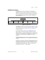
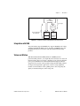
IMAQ
™
IMAQ PCI-1428
User Manual
High-Quality Camera Link Image
Acquisition Device for PCI
IMAQ PCI-1428 User Manual
January 2002 Edition
Part Number 322862B-01
Support
Worldwide Technical Support and Product Information
ni.com
National Instruments Corporate Headquarters
11500 North Mopac Expressway
Austin, Texas 78759-3504 USA Tel: 512 683 0100
Worldwide Offices
Australia 03 9879 5166, Austria 0662 45 79 90 0, Belgium 02 757 00 20, Brazil 011 3262 3599,
Canada (Calgary) 403 274 9391, Canada (Montreal) 514 288 5722, Canada (Ottawa) 613 233 5949,
Canada (Québec) 514 694 8521, Canada (Toronto) 905 785 0085, China (Shanghai) 021 6555 7838,
China (ShenZhen) 0755 3904939, Czech Republic 02 2423 5774, Denmark 45 76 26 00, Finland 09 725 725 11,
France 01 48 14 24 24, Germany 089 741 31 30, Greece 30 1 42 96 427, Hong Kong 2645 3186,
India 91 80 535 5406, Israel 03 6393737, Italy 02 413091, Japan 03 5472 2970, Korea 02 3451 3400,
Malaysia 603 9596711, Mexico 001 800 010 0793, Netherlands 0348 433466, New Zealand 09 914 0488,
Norway 32 27 73 00, Poland 0 22 528 94 06, Portugal 351 210 311 210, Russia 095 238 7139,
Singapore 2265886, Slovenia 386 3 425 4200, South Africa 11 805 8197, Spain 91 640 0085,
Sweden 08 587 895 00, Switzerland 056 200 51 51, Taiwan 02 2528 7227, United Kingdom 01635 523545
For further support information, see the Technical Support Resources appendix. To comment on the
documentation, send e-mail to [email protected].
© 2001, 2002 National Instruments Corporation. All rights reserved.
Important Information
Warranty
The IMAQ PCI-1428 is warranted against defects in materials and workmanship for a period of one year from the date of shipment, as
evidenced by receipts or other documentation. National Instruments will, at its option, repair or replace equipment that proves to be defective
during the warranty period. This warranty includes parts and labor.
The media on which you receive National Instruments software are warranted not to fail to execute programming instructions, due to defects
in materials and workmanship, for a period of 90 days from date of shipment, as evidenced by receipts or other documentation. National
Instruments will, at its option, repair or replace software media that do not execute programming instructions if National Instruments receives
notice of such defects during the warranty period. National Instruments does not warrant that the operation of the software shall be
uninterrupted or error free.
A Return Material Authorization (RMA) number must be obtained from the factory and clearly marked on the outside of the package before
any equipment will be accepted for warranty work. National Instruments will pay the shipping costs of returning to the owner parts which are
covered by warranty.
National Instruments believes that the information in this document is accurate. The document has been carefully reviewed for technical
accuracy. In the event that technical or typographical errors exist, National Instruments reserves the right to make changes to subsequent
editions of this document without prior notice to holders of this edition. The reader should consult National Instruments if errors are suspected.
In no event shall National Instruments be liable for any damages arising out of or related to this document or the information contained in it.
EXCEPT AS SPECIFIED HEREIN, NATIONAL INSTRUMENTS MAKES NO WARRANTIES , EXPRESS OR IMPLIED, AND SPECIFICALLY DISCLAIMS ANY WARRANTY OF
MERCHANTABILITY OR FITNESS FOR A PARTICULAR PURPOSE . C USTOMER’S RIGHT TO RECOVER DAMAGES CAUSED BY FAULT OR NEGLIGENCE ON THE PART OF
NATIONAL INSTRUMENTS SHALL BE LIMITED TO THE AMOUNT THERETOFORE PAID BY THE CUSTOMER. NATIONAL INSTRUMENTS WILL NOT BE LIABLE FOR
DAMAGES RESULTING FROM LOSS OF DATA, PROFITS, USE OF PRODUCTS, OR INCIDENTAL OR CONSEQUENTIAL DAMAGES, EVEN IF ADVISED OF THE POSSIBILITY
THEREOF. This limitation of the liability of National Instruments will apply regardless of the form of action, whether in contract or tort, including
negligence. Any action against National Instruments must be brought within one year after the cause of action accrues. National Instruments
shall not be liable for any delay in performance due to causes beyond its reasonable control. The warranty provided herein does not cover
damages, defects, malfunctions, or service failures caused by owner’s failure to follow the National Instruments installation, operation, or
maintenance instructions; owner’s modification of the product; owner’s abuse, misuse, or negligent acts; and power failure or surges, fire,
flood, accident, actions of third parties, or other events outside reasonable control.
Copyright
Under the copyright laws, this publication may not be reproduced or transmitted in any form, electronic or mechanical, including photocopying,
recording, storing in an information retrieval system, or translating, in whole or in part, without the prior written consent of National
Instruments Corporation.
Trademarks
CVI™, IMAQ™ , LabVIEW™, Measurement Studio™ , National Instruments™, and ni.com™ are trademarks of National Instruments
Corporation.
Product and company names mentioned herein are trademarks or trade names of their respective companies.
Patents
For patents covering National Instruments products, refer to the appropriate location: Help»Patents in your software, the patents.txt file
on your CD, or ni.com/patents.
WARNING REGARDING USE OF NATIONAL INSTRUMENTS PRODUCTS
(1) NATIONAL INSTRUMENTS PRODUCTS ARE NOT DESIGNED WITH COMPONENTS AND TESTING FOR A LEVEL OF
RELIABILITY SUITABLE FOR USE IN OR IN CONNECTION WITH SURGICAL IMPLANTS OR AS CRITICAL COMPONENTS IN
ANY LIFE SUPPORT SYSTEMS WHOSE FAILURE TO PERFORM CAN REASONABLY BE EXPECTED TO CAUSE SIGNIFICANT
INJURY TO A HUMAN.
(2) IN ANY APPLICATION, INCLUDING THE ABOVE, RELIABILITY OF OPERATION OF THE SOFTWARE PRODUCTS CAN BE
IMPAIRED BY ADVERSE FACTORS, INCLUDING BUT NOT LIMITED TO FLUCTUATIONS IN ELECTRICAL POWER SUPPLY,
COMPUTER HARDWARE MALFUNCTIONS, COMPUTER OPERATING SYSTEM SOFTWARE FITNESS, FITNESS OF COMPILERS
AND DEVELOPMENT SOFTWARE USED TO DEVELOP AN APPLICATION, INSTALLATION ERRORS, SOFTWARE AND
HARDWARE COMPATIBILITY PROBLEMS, MALFUNCTIONS OR FAILURES OF ELECTRONIC MONITORING OR CONTROL
DEVICES, TRANSIENT FAILURES OF ELECTRONIC SYSTEMS (HARDWARE AND/OR SOFTWARE), UNANTICIPATED USES OR
MISUSES, OR ERRORS ON THE PART OF THE USER OR APPLICATIONS DESIGNER (ADVERSE FACTORS SUCH AS THESE ARE
HEREAFTER COLLECTIVELY TERMED “SYSTEM FAILURES”). ANY APPLICATION WHERE A SYSTEM FAILURE WOULD
CREATE A RISK OF HARM TO PROPERTY OR PERSONS (INCLUDING THE RISK OF BODILY INJURY AND DEATH) SHOULD
NOT BE RELIANT SOLELY UPON ONE FORM OF ELECTRONIC SYSTEM DUE TO THE RISK OF SYSTEM FAILURE. TO AVOID
DAMAGE, INJURY, OR DEATH, THE USER OR APPLICATION DESIGNER MUST TAKE REASONABLY PRUDENT STEPS TO
PROTECT AGAINST SYSTEM FAILURES, INCLUDING BUT NOT LIMITED TO BACK-UP OR SHUT DOWN MECHANISMS.
BECAUSE EACH END-USER SYSTEM IS CUSTOMIZED AND DIFFERS FROM NATIONAL INSTRUMENTS' TESTING
PLATFORMS AND BECAUSE A USER OR APPLICATION DESIGNER MAY USE NATIONAL INSTRUMENTS PRODUCTS IN
COMBINATION WITH OTHER PRODUCTS IN A MANNER NOT EVALUATED OR CONTEMPLATED BY NATIONAL
INSTRUMENTS, THE USER OR APPLICATION DESIGNER IS ULTIMATELY RESPONSIBLE FOR VERIFYING AND VALIDATING
THE SUITABILITY OF NATIONAL INSTRUMENTS PRODUCTS WHENEVER NATIONAL INSTRUMENTS PRODUCTS ARE
INCORPORATED IN A SYSTEM OR APPLICATION, INCLUDING, WITHOUT LIMITATION, THE APPROPRIATE DESIGN,
PROCESS AND SAFETY LEVEL OF SUCH SYSTEM OR APPLICATION.
Compliance
FCC/Canada Radio Frequency Interference Compliance*
Determining FCC Class
The Federal Communications Commission (FCC) has rules to protect wireless communications from interference. The FCC
places digital electronics into two classes. These classes are known as Class A (for use in industrial-commercial locations only)
or Class B (for use in residential or commercial locations). Depending on where it is operated, this product could be subject to
restrictions in the FCC rules. (In Canada, the Department of Communications (DOC), of Industry Canada, regulates wireless
interference in much the same way.)
Digital electronics emit weak signals during normal operation that can affect radio, television, or other wireless products. By
examining the product you purchased, you can determine the FCC Class and therefore which of the two FCC/DOC Warnings
apply in the following sections. (Some products may not be labeled at all for FCC; if so, the reader should then assume these are
Class A devices.)
FCC Class A products only display a simple warning statement of one paragraph in length regarding interference and undesired
operation. Most of our products are FCC Class A. The FCC rules have restrictions regarding the locations where FCC Class A
products can be operated.
FCC Class B products display either a FCC ID code, starting with the letters EXN,
or the FCC Class B compliance mark that appears as shown here on the right.
Consult the FCC Web site http://www.fcc.gov for more information.
FCC/DOC Warnings
This equipment generates and uses radio frequency energy and, if not installed and used in strict accordance with the instructions
in this manual and the CE Mark Declaration of Conformity**, may cause interference to radio and television reception.
Classification requirements are the same for the Federal Communications Commission (FCC) and the Canadian Department
of Communications (DOC).
Changes or modifications not expressly approved by National Instruments could void the user’s authority to operate the
equipment under the FCC Rules.
Class A
Federal Communications Commission
This equipment has been tested and found to comply with the limits for a Class A digital device, pursuant to part 15 of the FCC
Rules. These limits are designed to provide reasonable protection against harmful interference when the equipment is operated
in a commercial environment. This equipment generates, uses, and can radiate radio frequency energy and, if not installed and
used in accordance with the instruction manual, may cause harmful interference to radio communications. Operation of this
equipment in a residential area is likely to cause harmful interference in which case the user will be required to correct
the interference at his own expense.
Canadian Department of Communications
This Class A digital apparatus meets all requirements of the Canadian Interference-Causing Equipment Regulations.
Cet appareil numérique de la classe A respecte toutes les exigences du Règlement sur le matériel brouilleur du Canada.
Class B
Federal Communications Commission
This equipment has been tested and found to comply with the limits for a Class B digital device, pursuant to part 15 of the
FCC Rules. These limits are designed to provide reasonable protection against harmful interference in a residential installation.
This equipment generates, uses and can radiate radio frequency energy and, if not installed and used in accordance with the
instructions, may cause harmful interference to radio communications. However, there is no guarantee that interference will not
occur in a particular installation. If this equipment does cause harmful interference to radio or television reception, which can
be determined by turning the equipment off and on, the user is encouraged to try to correct the interference by one or more of
the following measures:
• Reorient or relocate the receiving antenna.
• Increase the separation between the equipment and receiver.
• Connect the equipment into an outlet on a circuit different from that to which the receiver is connected.
• Consult the dealer or an experienced radio/TV technician for help.
Canadian Department of Communications
This Class B digital apparatus meets all requirements of the Canadian Interference-Causing Equipment Regulations.
Cet appareil numérique de la classe B respecte toutes les exigences du Règlement sur le matériel brouilleur du Canada.
European Union - Compliance to EEC Directives
Readers in the EU/EEC/EEA must refer to the Manufacturer's Declaration of Conformity (DoC) for information** pertaining
to the CE Mark compliance scheme. The Manufacturer includes a DoC for most every hardware product except for those bought
for OEMs, if also available from an original manufacturer that also markets in the EU, or where compliance is not required as
for electrically benign apparatus or cables.
* Certain exemptions may apply in the USA, see FCC Rules §15.103 Exempted devices, and §15.105(c). Also available in
sections of CFR 47.
** The CE Mark Declaration of Conformity will contain important supplementary information and instructions for the user or
installer.
Conventions
This manual uses the following conventions:
<>
Angle brackets that contain numbers separated by an ellipsis represent a
range of values associated with a bit or signal name—for example,
DBIO<3..0>.
»
The » symbol leads you through nested menu items and dialog box options
to a final action. The sequence File»Page Setup»Options directs you to
pull down the File menu, select the Page Setup item, and select Options
from the last dialog box.
This icon denotes a note, which alerts you to important information.
This icon denotes a caution, which advises you of precautions to take to
avoid injury, data loss, or a system crash.
bold
Bold text denotes items that you must select or click on in the software,
such as menu items and dialog-box options. Bold text also denotes
parameter names.
italic
Italic text denotes variables, emphasis, a cross reference, or an introduction
to a key concept. This font also denotes text that is a placeholder for a word
or value that you must supply.
monospace
Text in this font denotes text or characters that you should enter from the
keyboard, sections of code, programming examples, and syntax examples.
This font is also used for the proper names of disk drives, paths, directories,
programs, subprograms, subroutines, device names, functions, operations,
variables, filenames and extensions, and code excerpts.
Contents
Chapter 1
Introduction
About the IMAQ PCI-1428 ...........................................................................................1-1
Camera Link ..................................................................................................................1-2
Overview .........................................................................................................1-2
Interfacing with the PCI-1428 .......................................................................................1-2
Software Programming Choices ....................................................................................1-3
NI-IMAQ Driver Software ..............................................................................1-5
National Instruments IMAQ Vision ................................................................1-6
IMAQ Vision Builder......................................................................................1-6
Integration with DAQ......................................................................................1-7
Vision and Motion ...........................................................................................1-7
Chapter 2
Installation
What You Need to Get Started ......................................................................................2-1
Optional Equipment .......................................................................................................2-2
Setting up Your IMAQ System .....................................................................................2-2
Unpacking ......................................................................................................................2-4
Safety Information .........................................................................................................2-4
Installation .....................................................................................................................2-6
Configuring the PCI-1428 .............................................................................................2-7
Chapter 3
Hardware Overview
Functional Overview......................................................................................................3-1
Camera Link and PCI-1428.............................................................................3-2
Base Configuration ...........................................................................3-2
Medium Configuration......................................................................3-3
Data Transmission ...........................................................................................3-3
LUTs................................................................................................................3-3
Multiple-Tap Data Formatter ..........................................................................3-4
SDRAM...........................................................................................................3-4
Trigger Control and Mapping Circuitry ..........................................................3-4
High-Speed Timing .........................................................................................3-4
Acquisition, Scaling, ROI................................................................................3-5
Scatter-Gather DMA Controllers ....................................................................3-5
Bus Master PCI Interface ................................................................................3-5
© National Instruments Corporation
vii
IMAQ PCI-1428 User Manual
Contents
Start Conditions............................................................................................... 3-5
Acquisition Window Control .......................................................................... 3-6
Serial Interface ................................................................................................ 3-6
Chapter 4
Signal Connections
Connectors..................................................................................................................... 4-1
MDR 26-Pin Connector .................................................................................. 4-2
68-Pin VHDCI Connector............................................................................... 4-2
Connector Signal Connection Descriptions .................................................... 4-3
Appendix A
Specifications
Appendix B
Cabling
Appendix C
Technical Support Resources
Glossary
Index
IMAQ PCI-1428 User Manual
viii
ni.com
1
Introduction
This chapter provides an overview of the PCI-1428 image acquisition
device, the Camera Link standard, Camera Link/PCI-1428 interfacing
guidelines, and your software programming choices.
About the IMAQ PCI-1428
The PCI-1428 is a highly flexible IMAQ device that supports a diverse
range of Camera Link-compatible cameras from various camera
companies. The PCI-1428 acquires digital images in real time and stores
the images in onboard frame memory or transfers them directly to system
memory. Featuring a high-speed data flow path, the PCI-1428 is ideal for
both industrial and scientific environments.
The PCI-1428 is easy to install and configure. It ships with NI-IMAQ, the
National Instruments complete IMAQ driver software you can use to
directly control the PCI-1428 and other National Instruments IMAQ
hardware products. With NI-IMAQ, you can quickly and easily start your
applications without having to program the device at the register level.
The PCI-1428 supports the Camera Link Base configuration, and the
VHDCI 68-pin connector provides access to the 8-bit × 4 mode of the
Camera Link Medium configuration. For further configuration
information, see the Camera Link and PCI-1428 section in Chapter 3,
Hardware Overview.
The VHDCI 68-pin connector has four external input/output (I/O) lines you
can use as triggers or as high-speed digital I/O lines.
Note To use the trigger lines as digital I/O lines, go to the LabVIEW palette, and select
Motion & Vision»Image Acquisition»Signal I/O VIs.
For more advanced digital or analog system triggering or digital I/O lines,
you can use the PCI-1428 and NI-IMAQ with the National Instruments data
acquisition (DAQ) or motion control product lines.
© National Instruments Corporation
1-1
IMAQ PCI-1428 User Manual
Chapter 1
Introduction
Easily synchronizing several functions to a common trigger or timing event
is a common challenge with image acquisition devices. The PCI-1428 uses
the Real-Time System Integration (RTSI) bus to solve this problem. The
RTSI bus uses National Instruments RTSI bus interface and ribbon cable to
route additional timing and trigger signals between the PCI-1428 and up to
four National Instruments DAQ, motion control, or IMAQ devices. The
RTSI bus can even synchronize multiple IMAQ hardware captures.
Detailed specifications of the PCI-1428 are in Appendix A, Specifications.
Camera Link
This section provides a brief overview of the Camera Link standard.
For more detailed information about Camera Link specifications, reference
the Specifications of the Camera Link Interface Standard for Digital
Cameras and Frame Grabbers manual. This manual is available on several
Web sites, including the Automated Imaging Association site at
machinevisiononline.org.
Overview
Developed by a consortium of camera and frame grabber manufacturers,
Camera Link is a standard for interfacing digital cameras with image
acquisition devices. Camera Link simplifies connectivity between the
image acquisition device and the camera by defining a single standard
connector for both. This standard ensures compatibility of devices bearing
the Camera Link logo.
The basis for the Camera Link standard is the National Semiconductor
Channel Link chipset, a data transmission method consisting of a
general-purpose transmitter/receiver pair. The Channel Link driver takes
28 bits of parallel digital data and a clock and serializes the stream to four
LVDS (EIA-644) data streams and an LVDS clock, providing high-speed
data transmission across 10 wires and over distances of up to 10 m.
Interfacing with the PCI-1428
The Camera Link standard defines physical connections between image
acquisition devices and Camera Link cameras, and it allows for flexibility
of image format and data transfer protocols. The camera manufacturer
defines image parameters, such as image resolution and the number of bits
per pixel. Camera control parameters, such as frame-on-demand and
exposure control signals, are also defined by the camera manufacturer.
IMAQ PCI-1428 User Manual
1-2
ni.com
Chapter 1
Introduction
These variable parameters are defined on a per-camera basis in a camera
file (camera_model.icd) supplied by National Instruments. The
NI-IMAQ driver software uses the information in this camera file to
program the PCI-1428 to acquire images from a specific camera. Without
this camera file, the driver does not have the information necessary to
configure the PCI-1428 for acquisition.
Measurement & Automation Explorer (MAX), the National Instruments
configuration utility, provides a simple interface for associating a camera
file with the PCI-1428. Use the following guidelines to access the camera
file in MAX:
1.
Launch MAX, and expand the Devices and Interfaces branch of the
configuration tree.
2.
Expand the IMAQ PCI-1428 branch.
3.
Right-click Channel 0, and select Camera.
4.
Select your camera from the pop-up menu. If your camera is not in
the pop-up menu, verify that the camera file is installed in the
NI-IMAQ/Data directory.
Many camera files are installed on your computer when you install
NI-IMAQ, and many more are available for download from the National
Instruments Camera Advisor at ni.com\camera. When installing new
camera files, save them to the Data folder located at Program Files\
National Instruments\NI-IMAQ\Data.
Contact National Instruments technical support to request camera files not
available in the Camera Advisor. See Appendix C, Technical Support
Resources, for information on National Instruments technical support.
Software Programming Choices
Use NI-IMAQ, the National Instruments image acquisition driver software,
to program your IMAQ device to acquire, display, and save images. You
can use NI-IMAQ with other National Instruments software for a complete
image acquisition and analysis solution, as shown in Figure 1-1.
NI-IMAQ works with LabVIEW, LabWindows/CVI, Visual C++, and
Visual Basic. National Instruments IMAQ Vision adds powerful image
processing and analysis to these programming environments. You can also
use IMAQ Vision Builder to quickly and easily prototype your IMAQ
image analysis applications.
© National Instruments Corporation
1-3
IMAQ PCI-1428 User Manual
Chapter 1
Introduction
Vision Software
IMAQ Vision
Image
Analysis
Blob
Analysis
Pattern
Matching
Color Matching
and Analysis
Filters
Gauging and
Measurement
Display
and ROI
Morphology
Application Software
Measurement Studio
(LabWindows/CVI, Visual C++, Visual Basic)
LabVIEW
NI-IMAQ
IMAQ
Driver Software
NI-DAQ
Hardware
DAQ
NI-Motion
ValueMotion/
FlexMotion
Figure 1-1. The Relationship between the Programming Environment,
NI-IMAQ, and Hardware
IMAQ PCI-1428 User Manual
1-4
ni.com
Chapter 1
Introduction
NI-IMAQ Driver Software
The NI-IMAQ driver software is included with your IMAQ device.
NI-IMAQ has an extensive library of functions you can call from your
application programming environment. These functions include routines
for video configuration, image acquisition (continuous and single-shot),
memory buffer allocation, trigger control, and device configuration,
as shown in Figure 1-2.
NI-IMAQ
Image
Acquisition
Triggering
and Timing
DAQ
Synchronization
Buffer Control
Camera Control
Lookup Table
Control
Figure 1-2. NI-IMAQ Functions
The NI-IMAQ driver software performs all functions required for acquiring
and saving images, but it does not perform any image analysis. For image
analysis functionality, refer to the National Instruments IMAQ Vision
section in this chapter.
For maximum flexibility and performance, NI-IMAQ features both
high-level and low-level functions. Examples of high-level functions
include the functions to acquire images in single-shot or continuous mode.
An example of a low-level function is configuring an image sequence, since
it requires advanced understanding of the IMAQ device and image
acquisition.
NI-IMAQ internally resolves many of the complex issues between the
computer and the IMAQ device, such as programming interrupts and DMA
controllers.
NI-IMAQ is also the interface path between LabVIEW, LabWindows/CVI,
or a text-based programming environment and your IMAQ device. The
NI-IMAQ software kit includes a series of libraries for image acquisition
for LabVIEW and Measurement Studio, which contains libraries for
LabWindows/CVI, Visual C++, and Visual Basic.
© National Instruments Corporation
1-5
IMAQ PCI-1428 User Manual
Chapter 1
Introduction
National Instruments IMAQ Vision
IMAQ Vision is an image acquisition, processing, and analysis library of
more than 200 functions for grayscale, color, and binary image display,
image processing, pattern matching, shape matching, blob analysis,
gauging, and measurement.
For unique image processing, you can use IMAQ Vision functions
individually or in combination. With IMAQ Vision you can acquire,
display, manipulate, and store images as well as perform image analysis,
processing, and interpretation. Using IMAQ Vision, imaging novices and
experts can program the most basic or complicated image applications
without knowledge of any algorithm implementations.
IMAQ Vision is available for LabVIEW and Measurement Studio, which
includes support for LabWindows/CVI, Visual C++, and Visual Basic.
IMAQ Vision Builder
IMAQ Vision Builder is an interactive prototyping tool for machine vision
and scientific imaging developers. With IMAQ Vision Builder, you can
prototype vision software quickly or test how various vision image
processing functions work.
As shown in Figure 1-3, IMAQ Vision Builder generates a Builder file,
which is a text description containing a recipe of the machine vision
and image processing functions. This Builder file provides a guide you can
use for developing applications into any development environment, such as
LabWindows/CVI or Visual Basic, using the IMAQ Vision machine vision
and image processing libraries. Using the LabVIEW VI creation wizard,
you can create a LabVIEW VI that performs the prototype that you created
in IMAQ Vision Builder.
IMAQ PCI-1428 User Manual
1-6
ni.com
Chapter 1
Introduction
IMAQ
Vision Builder
Prototype
Builder File
Vision Application
Development
IMAQ Vision
IMAQ Vision
LabVIEW
Application
Software
Figure 1-3. IMAQ Vision Builder and Application Development Tools
Integration with DAQ
Any platform that supports NI-IMAQ also supports NI-DAQ and a variety
of National Instruments DAQ devices, allowing your IMAQ device and
NI-IMAQ development to integrate with National Instruments DAQ
products.
Vision and Motion
With National Instruments IMAQ hardware and IMAQ Vision
pattern-matching software, you can quickly and accurately locate objects in
instances where objects vary in size, orientation, focus, and even when the
part is poorly illuminated. Use National Instruments high-performance
stepper and servo motion control products with pattern-matching software
for inspection and guidance applications, such as locating alignment
markers on semiconductor wafers, guiding robotic arms, inspecting the
quality of manufactured parts, and locating cells.
© National Instruments Corporation
1-7
IMAQ PCI-1428 User Manual
2
Installation
This chapter contains a list of necessary and optional items for getting
started acquiring images with your IMAQ device. This chapter also
explains how to unpack, configure, and install your IMAQ device.
What You Need to Get Started
You need the following items to set up and use the PCI-1428:
❑ PCI-1428
❑ Getting Started with Your IMAQ System
❑ IMAQ PCI-1428 User Manual
❑ NI-IMAQ Release Notes
❑ NI-IMAQ for Windows 2000/NT/Me/9x and documentation
❑ Pentium-based PCI computer running Windows XP/2000/Me/NT/9x
❑ Camera Link camera
❑ MDR 26-pin Camera Link cable from 3M
❑ Optional software packages and documentation:
© National Instruments Corporation
–
IMAQ Vision for LabVIEW or Measurement Studio
(LabWindows/CVI, Visual C++, Visual Basic)
–
IMAQ Vision Builder
–
LabVIEW
–
Measurement Studio (LabWindows/CVI, tools for Visual Basic)
2-1
IMAQ PCI-1428 User Manual
Chapter 2
Installation
Optional Equipment
National Instruments offers a variety of products for use with the PCI-1428,
including the following:
•
MDR 26-pin Camera Link cable from 3M for Base configuration
•
IMAQ D6804 breakout cable (for external triggering only)
•
RTSI bus cables for connecting the PCI-1428 to other IMAQ,
motion control, or DAQ devices
•
Other National Instruments DAQ devices for enhanced triggering,
timing, or input/output
For more specific information about these products, refer to the
National Instruments catalog or Web site, or call the office nearest you.
Setting up Your IMAQ System
Use Figure 2-1 while installing software and hardware, configuring
hardware, and using NI-IMAQ in application programs.
Follow the instructions in the Getting Started with Your IMAQ System
document while installing the NI-IMAQ software and IMAQ hardware.
When accessing the NI-IMAQ device drivers through a programming
environment, read the NI-IMAQ Release Notes and the NI-IMAQ User
Manual for help in getting started.
IMAQ PCI-1428 User Manual
2-2
ni.com
Chapter 2
Installation
Read the Getting Started with Your IMAQ System
document and the NI-IMAQ release notes to install
your NI-IMAQ software, IMAQ hardware,
and documentation.
Configure your hardware using
Measurement & Automation Explorer and
online help.
LabVIEW
Read:
• The section in chapter 4 in the
NI-IMAQ User Manual for
information on using LabVIEW
with your IMAQ hardware.
• NI-IMAQ VI online help
• Your IMAQ Vision for
LabVIEW documentation
if you are using IMAQ
Vision for LabVIEW
What
application software
are you using?
Measurement
Studio
(Visual Basic)
Read the NI-IMAQ User Manual
for information on using
NI-IMAQ in your
application environment.
Measurement Studio
(LabWindows/CVI, Visual C++,
Borland C++)
Read Chapter 1, Introduction
to NI-IMAQ, in the
NI-IMAQ User Manual.
Read the sections in
chapters 2 and 3 in the NI-IMAQ
User Manual that apply to the
function groups you
will use in your application.
Look at the self-documented
example source code on your
distribution CD for your
application language
and environment.
Use the NI-IMAQ Function
Reference Manual when you
need specific information about
individual NI-IMAQ functions.
If you are using IMAQ Vision for
LabWindows/CVI, read the
documentation for IMAQ Vision
for LabWindows/CVI.
Figure 2-1. How to Set up Your IMAQ System
© National Instruments Corporation
2-3
IMAQ PCI-1428 User Manual
Chapter 2
Installation
Unpacking
The PCI-1428 ships in an antistatic package to prevent electrostatic
discharge from damaging board components. To avoid such damage in
handling the board, take the following precautions:
•
Ground yourself via a grounding strap or by holding a grounded object,
such as your computer chassis.
•
Touch the antistatic package to a metal part of your computer chassis
before removing the board from the package.
•
Remove the board from the package and inspect the board for loose
components or any other signs of damage. Notify National Instruments
if the board appears damaged in any way. Do not install a damaged
board in your computer.
•
Never touch the exposed pins of connectors.
Safety Information
The following paragraphs contain important safety information you must follow
when installing and operating the device.
Caution
Do not operate the device in a manner not specified in the documentation.
Misuse of the device may result in a hazard and may compromise the safety
protection built into the device. If the device is damaged, turn it off and do
not use it until service-trained personnel can check its safety. If necessary,
return the device to National Instruments for repair.
Keep away from live circuits. Do not remove equipment covers or shields
unless you are trained to do so. If signal wires are connected to the device,
hazardous voltages can exist even when the equipment is turned off. To
avoid a shock hazard, do not perform procedures involving cover or shield
removal unless you are qualified to do so. Disconnect all field power prior
to removing covers or shields.
If the device is rated for use with hazardous voltages (>30 Vrms, 42.4 Vpk,
or 60 Vdc), it may require a safety earth-ground connection wire. See the
device specifications for maximum voltage ratings.
Because of the danger of introducing additional hazards, do not install
unauthorized parts or modify the device. Use the device only with the
chassis, modules, accessories, and cables specified in the installation
IMAQ PCI-1428 User Manual
2-4
ni.com
Chapter 2
Installation
instructions. All covers and filler panels must be installed while operating
the device.
Do not operate the device in an explosive atmosphere or where flammable
gases or fumes may be present. Operate the device only at or below the
pollution degree stated in the specifications. Pollution consists of any
foreign matter—solid, liquid, or gas—that may reduce dielectric strength
or surface resistivity. Pollution degrees are listed below.
•
Pollution Degree 1—No pollution or only dry, nonconductive
pollution occurs. The pollution has no effect.
•
Pollution Degree 2—Normally only nonconductive pollution occurs.
Occasionally, nonconductive pollution becomes conductive because of
condensation.
•
Pollution Degree 3—Conductive pollution or dry, nonconductive
pollution occurs. Nonconductive pollution becomes conductive
because of condensation.
Clean the device and accessories by brushing off light dust with a soft,
nonmetallic brush. Remove other contaminants with a stiff, nonmetallic
brush. The unit must be completely dry and free from contaminants before
returning it to service.
You must insulate signal connections for the maximum voltage for which
the device is rated. Do not exceed the maximum ratings for the device.
Remove power from signal lines before connection to or disconnection
from the device.
Operate this device only at or below the installation category stated in the
specifications. Installation categories are listed below.
•
Installation Category IV—for measurements performed at the source
of the low-voltage (<1000 V) installation. Examples include electricity
meters, measurements on primary overcurrent protection devices,
and ripple-control units.
•
Installation Category III—for measurements performed in the building
installation. Examples include measurements on distribution boards,
circuit-breakers, wiring (including cables), bus bars, junction boxes,
switches, socket outlets in the fixed installation, equipment for
industrial use, and some other types of equipment, such as stationary
motors permanently connected to the fixed installation.
•
Installation Category II—for measurements performed on circuits
directly connected to the low-voltage installation. Examples include
© National Instruments Corporation
2-5
IMAQ PCI-1428 User Manual
Chapter 2
Installation
measurements on household appliances, portable tools, and other
similar equipment.
•
Installation Category I—for measurements performed on circuits not
directly connected to mains1. Examples include measurements on
circuits not derived from mains, and specially-protected (internal)
mains-derived circuits.
Figure 2-1 illustrates a sample installation.
Figure 2-2. Sample Installation
Installation
You can install the PCI-1428 in any available PCI expansion slot in your
computer. However, to achieve the best noise performance, leave as much
room as possible between the PCI-1428 and other boards and hardware.
Note You must install the NI-IMAQ driver software before installing the 1428 device. For
information on how to install NI-IMAQ, see the Getting Started with Your IMAQ System
document and the NI-IMAQ Release Notes.
Use the following guidelines for installing the PCI-1428:
1.
Verify that NI-IMAQ is installed on your computer.
2.
Turn off and unplug your computer.
To protect yourself and the computer from electrical hazards, the computer
should remain off until you finish installing the PCI-1428.
Caution
1
Mains is defined as the electricity supply system to which the equipment concerned is designed to be connected for either
powering the equipment or for measurement purposes.
IMAQ PCI-1428 User Manual
2-6
ni.com
Chapter 2
Installation
3.
Follow the electrostatic discharge guidelines in the Unpacking section
of this chapter.
4.
Remove the computer cover.
5.
Make sure there are no lit LEDs on the motherboard. If any are lit, wait
until they go out before continuing installation.
6.
Touch the metal part of the power supply case inside the computer to
discharge any static electricity that might be on your clothes or body.
7.
Locate the metal bracket that covers the cut-out in the back panel of
the chassis for the slot you have selected. Remove and save the
bracket-retaining screw and the bracket cover.
8.
Line up the PCI-1428 with the MDR 26-pin connector near the cut-out
on the computer’s back panel. Slowly push down on the top of the
PCI-1428 until its card-edge connector is resting on the expansion slot
receptacle. Using slow, evenly distributed pressure, press the PCI-1428
straight down until it is evenly positioned in the expansion slot.
9.
Reinstall the bracket-retaining screw to secure the PCI-1428 to the
back panel rail.
10. Replace the computer cover, and plug the computer in.
Your PCI-1428 is now installed.
Configuring the PCI-1428
Once you have installed the PCI-1428 and powered on your computer,
Windows will recognize the device and assign resources to it.
Use MAX to configure the PCI-1428 for acquisition. Refer to the
Interfacing with the PCI-1428 section in Chapter 1, Introduction, for
further information on using MAX to configure your IMAQ device.
© National Instruments Corporation
2-7
IMAQ PCI-1428 User Manual
3
Hardware Overview
This chapter provides an overview of PCI-1428 hardware functionality and
explains the operations of the device’s functional units.
Functional Overview
The PCI-1428 features a flexible, high-speed data path optimized for
receiving and formatting video data from Camera Link cameras.
Figure 3-1 illustrates the key functional components of the PCI-1428.
© National Instruments Corporation
3-1
IMAQ PCI-1428 User Manual
Chapter 3
Hardware Overview
Synchronous Dynamic RAM
Enables
Data
Channel
Link
Receiver
LUT
LUT
Data
IMAQ SDRAM
Data
Interface
PCI Interface
and
Scatter-Gather
DMA Controllers
Pixel Clock and Camera Enables
Pixel
Clock
Camera
Control
Advanced
Triggering
and Timing
Serial
Control
PCI Bus
26-Pin MDR Connector
Data
Acquisition, Scaling,
ROI, and Control
Differential
Converter
68-Pin VHDCI
UART
Data
Enables
RTSI Bus
Channel
Link
Receiver
Pixel
Clock
External Triggers
Figure 3-1. PCI-1428 Block Diagram
Camera Link and PCI-1428
The PCI-1428 supports the Camera Link Base configuration, as well as the
8-bit × 4 mode of the Camera Link Medium configuration.
Base Configuration
The Camera Link Base configuration places 24 data bits and four enable
signals (Frame Valid, Line Valid, Data Valid, and a spare) on a single
Channel Link part and cable.
The Base configuration includes asynchronous serial transmission as well
as four digital camera control lines for controlling exposure time, frame
rates, and other camera control signals. These four control lines are
IMAQ PCI-1428 User Manual
3-2
ni.com
Chapter 3
Hardware Overview
configured in the camera file to generate precise timing signals for
controlling digital camera acquisition.
Base configuration includes the following bit allocations:
•
8-bit × 1, 2, and 3 taps (channels)
•
10-bit × 1 and 2 taps
•
12-bit × 1 and 2 taps
•
14-bit × 1 tap
•
16-bit × 1 tap
•
24-bit RGB
Medium Configuration
The PCI-1428 supports the 8-bit × 4 tap of the Camera Link Medium
configuration. The Medium configuration requires using both connectors.
This configuration allows for more data throughput by offering
two synchronized data streams between the camera and the PCI-1428.
Data Transmission
A 28-to-4 serializing Channel Link chip drives the data and camera enable
signals across the Camera Link cable, and the camera’s pixel clock controls
the Channel Link’s data transmission. The four LVDS pairs are then
deserialized by another Channel Link chip on the PCI-1428.
Note Exact timing of camera and image acquisition device communication is camera
dependent. The Specifications of the Camera Link Interface Standard for Digital Cameras
and Frame Grabbers manual fully explains the Camera Link timing requirements.
LUTs
The PCI-1428 offers two 64 KB × 16-bit lookup tables (LUTs) that can
perform up to four 256 KB × 8-bit LUT operations, such as contrast
enhancement, data inversion, gamma manipulation, or other nonlinear
transfer functions.
© National Instruments Corporation
3-3
IMAQ PCI-1428 User Manual
Chapter 3
Hardware Overview
Multiple-Tap Data Formatter
Many digital cameras transfer multiple taps, or channels, of data
simultaneously to increase the frame rate of the camera. However, the data
in each tap may not be transferred in the traditional top-left to bottom-right
direction. Also, the taps may not transfer data in the same direction.
The multiple-tap data formatting circuitry on the PCI-1428 can reorder the
data from up to four taps. The data from each tap can be independently
scanned either from left-to-right or right-to-left and top-to-bottom or
bottom-to-top.
Note For your convenience, data reformatting instructions for these cameras have been
preprogrammed into the camera files.
SDRAM
The PCI-1428 has 16 MB of onboard high-speed synchronous dynamic
RAM (SDRAM). The PCI-1428 uses the onboard RAM as a FIFO buffer
to ensure acquisition. Even when the data rate from the camera exceeds PCI
throughput, you can acquire without interruption until the onboard RAM is
full.
Trigger Control and Mapping Circuitry
The trigger control and mapping circuitry routes, monitors, and drives
the external and RTSI bus trigger lines. You can configure each line to start
an acquisition on a rising or falling edge and drive each line asserted or
unasserted, much like a digital I/O line. You can also map pulses from the
high-speed timing circuitry or many of the PCI-1428 status signals to these
trigger lines. Four external and four RTSI bus triggers (all of which are
programmable for polarity and direction) are available for simultaneous
use.
High-Speed Timing
Built from high-speed counters, the high-speed timing circuitry on the
PCI-1428 can generate precise real-time control signals for your camera.
Map the output of this circuitry to a trigger line to provide accurate pulses
and pulse trains. Use these control signals to control exposure time and
frame rate.
Note For your convenience, the external control for cameras that support it has been
preprogrammed into the camera file. You can use MAX to specify the frequency and
IMAQ PCI-1428 User Manual
3-4
ni.com
Chapter 3
Hardware Overview
duration of these signals in easy-to-use units. See the Interfacing with the PCI-1428 section
in Chapter 1, Introduction, for information on camera files.
Acquisition, Scaling, ROI
The acquisition, scaling, and region-of-interest (ROI) circuitry monitors
incoming video signals and routes the active pixels to the multiple-tap data
formatter and SDRAM. The PCI-1428 can perform ROI and scaling on all
video lines and frames. Pixel and line scaling transfers multiples of two,
four, or eight pixels and lines to onboard memory. In an ROI acquisition,
select an area within the acquisition window to transfer across the PCI bus
to system memory.
Note You can use MAX to set the acquisition, scaling, and ROI parameters.
Scatter-Gather DMA Controllers
The PCI-1428 uses three independent onboard direct memory access
(DMA) controllers. The DMA controllers transfer data between the
onboard SDRAM memory buffers and the PCI bus. Each of these
controllers supports scatter-gather DMA, which allows the DMA controller
to reconfigure on the fly. The PCI-1428 can perform continuous image
transfers directly to either contiguous or fragmented memory buffers.
Bus Master PCI Interface
The PCI-1428 implements the PCI interface with a National Instruments
custom application-specific integrated circuit (ASIC), the PCI MITE.
The PCI interface can transfer data at a maximum rate of 133 MB/s
in bus master mode.
Start Conditions
The PCI-1428 can start acquisitions in the following ways:
•
Software control—The PCI-1428 supports software control of
acquisition start. You can configure the PCI-1428 to capture a fixed
number of frames. This configuration is useful for capturing a single
frame or a sequence of frames.
•
Trigger control—You can start an acquisition by enabling external
or RTSI bus trigger lines. Each of these inputs can start a video
acquisition on a rising or falling edge. You can use all four external
triggers and up to four RTSI bus triggers simultaneously.
© National Instruments Corporation
3-5
IMAQ PCI-1428 User Manual
Chapter 3
Hardware Overview
•
Delayed acquisition—Use either software or triggers to start
acquisitions instantaneously or after skipping a specific number of
frames. You can use delayed acquisition for post-trigger applications.
Acquisition Window Control
You can configure the following parameters on the PCI-1428 to control the
video acquisition window:
•
Acquisition window—The PCI-1428 allows the user to specify a
particular region of active pixels and active lines within the incoming
video data. The active pixel region selects the starting pixel and
number of pixels to be acquired relative to the assertion edge of the
horizontal (or line) enable signal from the camera. The active line
region selects the starting line and number of lines to be acquired
relative to the assertion edge of the vertical (or frame) enable signal.
•
Region of interest—The PCI-1428 uses a second level of active pixel
and active line regions for selecting a region of interest. Using the
region-of-interest circuitry, the device acquires only a selected subset
of the acquisition window.
•
Scaling down—The scaling-down circuitry also controls the active
acquisition region. The PCI-1428 can scale down a frame by reducing
the number of pixels per line, the number of lines per frame, or both.
For active pixel selection, the PCI-1428 selects every pixel, every other
pixel, every fourth pixel, or every eighth pixel. For active line
selection, the PCI-1428 selects every line, every other line, every
fourth line, or every eighth line. You can use the scaling-down circuitry
in conjunction with the region-of-interest circuitry.
Serial Interface
The PCI-1428 provides serial connections to and from the camera through
two LVDS pairs in the Camera Link cable. All Camera Link serial
communication uses one start bit, one stop bit, no parity, and no hardware
handshaking.
The PCI-1428 supports the following baud rates: 56000, 38400, 19200,
9600, 7200, 4800, 3600, 2400, 2000, 1800, 1200, 600, and 300.
You can use the serial interface interactively with MAX and
clsercon.exe, or programmatically with LabVIEW and C.
IMAQ PCI-1428 User Manual
3-6
ni.com
Chapter 3
Hardware Overview
Interactively:
•
MAX—Use MAX with a camera file containing preprogrammed
commands. When an acquisition is initiated, the commands are sent to
the camera.
•
clsercon.exe—Use National Instruments terminal emulator for
Camera Link, clsercon.exe, if a camera file with preprogrammed
serial commands does not exist for your camera. With
clsercon.exe, you can still communicate serially with your camera.
Go to <NI-IMAQ>/bin to access clsercon.exe.
Programmatically:
•
LabVIEW—Use the serial interface programmatically, through calls
to the NI-IMAQ driver using the IMAQ Serial Write and IMAQ Serial
Read VIs. Go to <LabVIEW>/vi.lib/vision/driver/
imaqll.llb to access these files.
•
C—Use the serial interface programmatically, through calls to the
NI-IMAQ driver using imgSessionSerialWrite and
imgSessionSerialRead.
Note clsercon.exe, IMAQ Serial Write, IMAQ Serial Read,
imgSessionSerialWrite, and imgSessionSerialRead are used for directly
accessing the PCI-1428 serial port and are not required for most users.
National Instruments also fully supports the recommended serial API
described in the Specifications of the Camera Link Interface Standard for
Digital Cameras and Frame Grabbers manual.
© National Instruments Corporation
3-7
IMAQ PCI-1428 User Manual
4
Signal Connections
This chapter describes the MDR 26-pin connector and the 68-pin VHDCI
connector on the PCI-1428 device.
Connectors
Figure 4-1 shows the connectors on the PCI-1428 device.
1
2
1
MDR 26-Pin Connector
2
68-Pin VHDCI Connector
Figure 4-1. PCI-1428 Connectors
© National Instruments Corporation
4-1
IMAQ PCI-1428 User Manual
Chapter 4
Signal Connections
MDR 26-Pin Connector
The MDR 26-pin connector provides reliable high-frequency transfer rates
between the camera and the acquisition device. To access this connector,
use a 3M Camera Link cable. For additional information on Camera Link
cables, including ordering information and cable lengths, see the Camera
Link Cables section in Appendix B, Cabling.
Figure 4-2 shows the PCI-1428 MDR 26-pin connector assignments. See
Table 4-1 for a description of the MDR-26 and 68-pin VHDCI signal
connections.
DGND
CC(4)+
CC(3)–
CC(2)+
CC(1)–
SerTFG–
SerTC+
X(3)–
XCLK–
X(2)–
X(1)–
X(0)–
DGND
14
15
16
17
18
19
20
21
22
23
24
25
26
1
2
3
4
5
6
7
8
9
10
11
12
13
DGND
CC(4)–
CC(3)+
CC(2)–
CC(1)+
SerTFG+
SerTC–
X(3)+
XCLK+
X(2)+
X(1)+
X(0)+
DGND
Figure 4-2. MDR 26-Pin Connector Assignments
68-Pin VHDCI Connector
The 68-pin VHDCI connector connects to external digital I/O lines and
triggers. To access these connections, build a custom cable or use an
optional cable from National Instruments. For information on building a
custom cable for the 68-pin VHDCI connector, see the 68-Pin VHDCI
Cable Specification section in Appendix B, Cabling.
Figure 4-3 shows the 68-pin VHDCI connector pinout. See Table 4-1 for a
description of the MDR-26 and 68-pin VHDCI signal connections.
IMAQ PCI-1428 User Manual
4-2
ni.com
Chapter 4
RESERVED
RESERVED
RESERVED
RESERVED
RESERVED
RESERVED
RESERVED
RESERVED
DGND
DGND
RESERVED
RESERVED
RESERVED
RESERVED
RESERVED
RESERVED
DGND
DGND
RESERVED
RESERVED
RESERVED
RESERVED
RESERVED
RESERVED
RESERVED
RESERVED
DGND
DGND
DGND
DGND
CHASSIS_GND
RESERVED
DGND
RESERVED
68
67
66
65
64
63
62
61
60
59
58
57
56
55
54
53
52
51
50
49
48
47
46
45
44
43
42
41
40
39
38
37
36
35
34
33
32
31
30
29
28
27
26
25
24
23
22
21
20
19
18
17
16
15
14
13
12
11
10
9
8
7
6
5
4
3
2
1
Signal Connections
RESERVED
RESERVED
RESERVED
RESERVED
RESERVED
RESERVED
RESERVED
RESERVED
DGND
Y (0)–
Y (0)+
Y (1)–
Y (1)+
Y (2)–
Y (2)+
YCLK –
YCLK+
Y (3)–
Y (3)+
RESERVED
RESERVED
RESERVED
RESERVED
RESERVED
RESERVED
RESERVED
TTL_TRIG(0)
TTL_TRIG(1)
TTL_TRIG(2)
TTL_TRIG(3)
CHASSIS_GND
RESERVED
DGND
RESERVED
Figure 4-3. 68-Pin VHDCI Connector Pin Assignments
Connector Signal Connection Descriptions
Table 4-1 describes the MDR-26 and 68-pin VHDCI signal connections.
Table 4-1. I/O Connector Signals
Signal Name
Description
TTL_TRIG
TTL external triggers/DIO lines (input/output)
DGND
A direct connection to digital GND on the 1428 device
CHASSIS_GND
A direct connection to the computer’s chassis, which is grounded through the
power cord
X<3..0>±
LVDS Base configuration data and enable signals from the acquisition device
to the camera
© National Instruments Corporation
4-3
IMAQ PCI-1428 User Manual
Chapter 4
Signal Connections
Table 4-1. I/O Connector Signals (Continued)
Signal Name
Description
Y<3..0>±
LVDS Medium configuration data and enable signals from the acquisition
device to the camera
XCLK±
Transmission clock on the Base configuration chip for Camera Link
communication between the acquisition device and the camera
YCLK±
Transmission clock on the Medium configuration chip for Camera Link
communication between the acquisition device and the camera
SerTC±
Serial transmission to the camera from the image acquisition device
SerTFG±
Serial transmission to the frame grabber from the camera
CC<4..1>±
Four LVDS pairs (defined as camera inputs and acquisition device outputs)
reserved for camera control
On some cameras, the camera controls allow the acquisition device to control
exposure time and frame rate.
IMAQ PCI-1428 User Manual
4-4
ni.com
A
Specifications
This appendix lists the specifications of the PCI-1428. These specifications
are typical at 25 °C, unless otherwise stated.
External Connections
Trigger sense .......................................... TTL
Trigger level ........................................... Programmable (rising or falling)
Pixel clock.............................................. Camera Link compatible
Enables ................................................... Camera Link compatible
Control signal......................................... Camera Link compatible
Video data .............................................. Camera Link compatible
Clocks
Pixel clock frequency range................... 20 to 50 MHz
Note Camera Link cameras must transmit at a minimum of 20 MHz.1
PCI Interface
PCI initiator (master) capability............. Supported
PCI target (slave) capability................... Supported
Data path ................................................ 32 bits
Card type ................................................ 32-bit half-size card
Parity generation/checking,
error reporting ........................................ Supported
1
This value corresponds to the post-serialization Camera Link cable transmission rate of 140 to 350 MHz.
© National Instruments Corporation
A-1
IMAQ PCI-1428 User Manual
Appendix A
Specifications
Target decode speed ...............................Medium (1 clock)
Target fast back-to-back capability ........Supported
PCI master performance
Ideal .................................................133 MB/s
Sustained..........................................100 MB/s
Power Requirements
Voltage....................................................+5 VDC (1.5 ADC)
+12 VDC (24 mA)
–12 VDC (20 mA)
Physical
Dimensions .............................................10.7 by 17.5 cm
(4.2 by 6.9 in.)
Weight ....................................................0.127 kg (0.28 lb)
Environment
Operating temperature ............................ 0 to 55 °C
Storage temperature ................................–20 to 70 °C
Relative humidity ...................................5 to 90%, noncondensing
Emissions................................................EN 55011:1991 Group 1 Class A
at 10 m FCC Class A at 10 m
IMAQ PCI-1428 User Manual
A-2
ni.com
B
Cabling
This appendix contains cabling requirements for the PCI-1428, including
Camera Link cable ordering information.
68-Pin VHDCI Cable Specification
National Instruments offers cables and accessories for connecting to video
sources, trigger sources, or synchronization sources. However, if you want
to develop your own cable for the 68-pin VHDCI connector, you must use
twisted pairs for each signal.
For information on connector pin assignments, see the Connectors section
in Chapter 4, Signal Connections.
Camera Link Cables
Use a 3M Camera Link cable or build your own cable (not recommended)
to connect your camera to the MDR 26-pin connector on the PCI-1428
device. Camera Link cables consist of two MDR-26 male plugs linked with
a twin-axial shielded cable and are available in two shell configurations.
For more information on Camera Link cables, reference the Specifications
of the Camera Link Interface Standard for Digital Cameras and Frame
Grabbers manual. This manual is available on several Web sites, including
the Automated Imaging Association site at machinevisiononline.org.
© National Instruments Corporation
B-1
IMAQ PCI-1428 User Manual
Appendix B
Cabling
Figure B-1 illustrates the Camera Link cable.
1
2
1
MDR 26-Pin Male Plug
2
2X Thumbscrews
Figure B-1. Camera Link Cable
Ordering Information
Camera Link cables are manufactured by 3M corporation and are available
from both National Instruments and 3M.
Two-meter Camera Link cables (part number 187676-02) are available
from the National Instruments Web site at ni.com/catalog. Camera
Link cables are available in 1 to 10 m lengths from the 3M Web site at
3m.com. See Figure B-2 for 3M part number information.
14X26-SZLB-XXX-0LC
Shell Retention Options:
B = Thumbscrew shell kit
T = Thumbscrew overmold shell
Length:
100 = 1 meter
200 = 2 meters
300 = 3 meters
450 = 4.5 meters
500 = 5 meters
700 = 7 meters
A00 = 10 meters
Figure B-2. 3M Part Number Ordering Information
IMAQ PCI-1428 User Manual
B-2
ni.com
Technical Support Resources
C
Web Support
National Instruments Web support is your first stop for help in solving
installation, configuration, and application problems and questions. Online
problem-solving and diagnostic resources include frequently asked
questions, knowledge bases, product-specific troubleshooting wizards,
manuals, drivers, software updates, and more. Web support is available
through the Technical Support section of ni.com.
NI Developer Zone
The NI Developer Zone at ni.com/zone is the essential resource for
building measurement and automation systems. At the NI Developer Zone,
you can easily access the latest example programs, system configurators,
tutorials, technical news, as well as a community of developers ready to
share their own techniques.
Customer Education
National Instruments provides a number of alternatives to satisfy your
training needs, from self-paced tutorials, videos, and interactive CDs to
instructor-led hands-on courses at locations around the world. Visit the
Customer Education section of ni.com for online course schedules,
syllabi, training centers, and class registration.
System Integration
If you have time constraints, limited in-house technical resources, or other
dilemmas, you may prefer to employ consulting or system integration
services. You can rely on the expertise available through our worldwide
network of Alliance Program members. To find out more about our
Alliance system integration solutions, visit the System Integration section
of ni.com.
© National Instruments Corporation
C-1
IMAQ PCI-1428 User Manual
Appendix C
Technical Support Resources
Worldwide Support
National Instruments has offices located around the world to help address
your support needs. You can access our branch office Web sites from the
Worldwide Offices section of ni.com. Branch office Web sites provide
up-to-date contact information, support phone numbers, e-mail addresses,
and current events.
If you have searched the technical support resources on our Web site and
still cannot find the answers you need, contact your local office or National
Instruments corporate. Phone numbers for our worldwide offices are listed
at the front of this manual.
IMAQ PCI-1428 User Manual
C-2
ni.com
Glossary
Prefix
Meaning
Value
k-
kilo-
10 3
M-
mega-
10 6
Numbers/Symbols
%
Percent.
+
Positive of, or plus.
/
Per.
Ω
Ohm.
±
Plus or minus.
–
Negative of, or minus.
A
A
Amperes.
AC
Alternating current.
acquisition window
The image size specific to a video standard or camera resolution.
active line region
The region of lines actively being stored. Defined by a line start (relative to
the vertical synchronization signal) and a line count.
active pixel region
The region of pixels actively being stored. Defined by a pixel start (relative
to the horizontal synchronization signal) and a pixel count.
address
Value that identifies a specific location (or series of locations) in memory.
ANSI
American National Standards Institute.
© National Instruments Corporation
G-1
IMAQ PCI-1428 User Manual
Glossary
API
Application programming interface.
area
A rectangular portion of an acquisition window or frame that is controlled
and defined by software.
array
Ordered, indexed set of data elements of the same type.
ASIC
Application-Specific Integrated Circuit. A proprietary semiconductor
component designed and manufactured to perform a set of specific
functions for specific customer needs.
B
b
Bit. One binary digit, either 0 or 1.
B
Byte. Eight related bits of data, an eight-bit binary number; also used to
denote the amount of memory required to store one byte of data
buffer
Temporary storage for acquired data.
bus
A group of conductors that interconnect individual circuitry in a computer,
such as the PCI bus; typically the expansion vehicle to which I/O or other
devices are connected.
C
C
Celsius.
cache
High-speed processor memory that buffers commonly used instructions or
data to increase processing throughput.
Camera Link
Interface standard for digital video data and camera control based on the
Channel Link chipset.
Channel Link
National Semiconductor chipset for high-speed data serialization and
deserialization for transmission across cables up to 10 m.
CMOS
Complementary metal-oxide semiconductor.
CPU
Central processing unit.
IMAQ PCI-1428 User Manual
G-2
ni.com
Glossary
D
DAQ
Data acquisition. (1) Collecting and measuring electrical signals from
sensors, transducers, and test probes or fixtures and inputting them to a
computer for processing. (2) Collecting and measuring the same kinds of
electrical signals with A/D or DIO boards plugged into a computer, and
possibly generating control signals with D/A and/or DIO boards in the
same computer.
DC
Direct current.
default setting
A default parameter value recorded in the driver; in many cases, the default
input of a control is a certain value (often 0) that means use the current
default setting.
DMA
Direct memory access. A method by which data can be transferred to and
from computer memory from and to a device or memory on the bus while
the processor does something else; DMA is the fastest method of
transferring data to/from computer memory.
DRAM
Dynamic RAM.
drivers
Software that controls a specific hardware device, such as an image
acquisition board.
dynamic range
The ratio of the largest signal level a circuit can handle to the smallest
signal level it can handle (usually taken to be the noise level), normally
expressed in decibels.
E
EEPROM
Electrically erasable programmable read-only memory. ROM that can be
erased with an electrical signal and reprogrammed.
external trigger
A voltage pulse from an external source that triggers an event such as
A/D conversion.
© National Instruments Corporation
G-3
IMAQ PCI-1428 User Manual
Glossary
F
FIFO
First-in first-out memory buffer. The first data stored is the first data sent
to the acceptor; FIFOs are used on IMAQ devices to temporarily store
incoming data until that data can be retrieved.
ft
Feet.
H
h
Hour.
Hz
Hertz. Frequency in units of one cycle per second.
I
I/O
Input/output. The transfer of data to/from a computer system involving
communications channels, operator interface devices, and/or data
acquisition and control interfaces.
IC
Integrated circuit.
IEEE
Institute of Electrical and Electronics Engineers.
in.
Inches.
instrument driver
A set of high-level software functions, such as NI-IMAQ, that control
specific plug-in computer boards. Instrument drivers are available in
several forms, ranging from a function callable from a programming
language to a virtual instrument (VI) in LabVIEW.
interrupt
A computer signal indicating that the CPU should suspend its current task
to service a designated activity.
interrupt level
The relative priority at which a device can interrupt.
IRQ
Interrupt request. See interrupt.
IMAQ PCI-1428 User Manual
G-4
ni.com
Glossary
K
k
Kilo. The standard metric prefix for 1,000, or 103, used with units of
measure such as volts, hertz, and meters.
K
Kilo. The prefix for 1,024, or 210, used with B in quantifying data or
computer memory.
kbytes/s
A unit for data transfer that means 1,000 or 103 bytes/s.
Kword
1,024 words of memory.
L
line count
The total number of horizontal lines in the picture.
LSB
Least significant bit.
LUT
Look-up table. Table containing values used to transform the gray-level
values of an image. For each gray-level value in the image, the
corresponding new value is obtained from the look-up table.
LVDS
Low Voltage Differential Signaling (EIA-644).
M
m
Meters.
M
(1) Mega, the standard metric prefix for 1 million or 106, when used with
units of measure such as volts and hertz; (2) mega, the prefix for 1,048,576,
or 220, when used with B to quantify data or computer memory.
MB
Megabyte of memory.
Mbytes/s
A unit for data transfer that means 1 million or 106 bytes/s.
memory buffer
See buffer.
memory window
Continuous blocks of memory that can be accessed quickly by changing
addresses on the local processor.
© National Instruments Corporation
G-5
IMAQ PCI-1428 User Manual
Glossary
MSB
Most significant bit.
MTBF
Mean time between failure.
mux
Multiplexer. A switching device with multiple inputs that selectively
connects one of its inputs to its output.
N
NI-IMAQ
Driver software for National Instruments IMAQ hardware.
NVRAM
Nonvolatile RAM. RAM that is not erased when a device loses power or is
turned off.
O
operating system
Base-level software that controls a computer, runs programs, interacts with
users, and communicates with installed hardware or peripheral devices.
P
PCI
Peripheral Component Interconnect. A high-performance expansion bus
architecture originally developed by Intel to replace ISA and EISA. PCI
offers a theoretical maximum transfer rate of 132 Mbytes/s.
pixel
Picture element. The smallest division that makes up the video scan line;
for display on a computer monitor, a pixel’s optimum dimension is square
(aspect ratio of 1:1, or the width equal to the height).
pixel clock
Divides the incoming horizontal video line into pixels.
pixel count
The total number of pixels between two horizontal synchronization signals.
The pixel count determines the frequency of the pixel clock.
protocol
The exact sequence of bits, characters, and control codes used to transfer
data between computers and peripherals through a communications
channel.
pts
Points.
IMAQ PCI-1428 User Manual
G-6
ni.com
Glossary
R
RAM
Random-access memory.
real time
A property of an event or system in which data is processed as it is acquired
instead of being accumulated and processed at a later time.
relative accuracy
A measure in LSB of the accuracy of an ADC; it includes all nonlinearity
and quantization errors but does not include offset and gain errors of the
circuitry feeding the ADC.
resolution
The smallest signal increment that can be detected by a measurement
system. Resolution can be expressed in bits, in proportions, or in
percent of full scale. For example, a system has 12-bit resolution, one
part in 4,096 resolution, and 0.0244 percent of full scale.
RGB
Color encoding scheme using red, green, and blue (RGB) color information
where each pixel in the color image is encoded using 32 bits: 8 bits for red,
8 bits for green, 8 bits for blue, and 8 bits for the alpha value (unused).
ribbon cable
A flat cable in which the conductors are side by side.
ROI
Region of interest. A hardware-programmable rectangular portion of the
acquisition window.
ROM
Read-only memory.
RTSI bus
Real-Time System Integration Bus. The National Instruments timing bus
that connects IMAQ and DAQ boards directly, by means of connectors on
top of the boards, for precise synchronization of functions.
S
s
Seconds.
saturation
The amount of white added to a pure color. Saturation relates to the richness
of a color. A saturation of zero corresponds to a pure color with no white
added. Pink is a red with low saturation.
scaling down circuitry
Circuitry that scales down the resolution of a video signal.
scatter-gather DMA
A type of DMA that allows the DMA controller to reconfigure on-the-fly.
SDRAM
Synchronous dynamic RAM.
© National Instruments Corporation
G-7
IMAQ PCI-1428 User Manual
Glossary
SRAM
Static RAM.
sync
Tells the display where to put a video picture. The horizontal sync indicates
the picture’s left-to-right placement and the vertical sync indicates
top-to-bottom placement.
system RAM
RAM installed on a personal computer and used by the operating system,
as contrasted with onboard RAM.
T
tap
A stream of pixels from a camera. Some cameras send multiple streams,
or taps, of data over a cable simultaneously to increase transfer rate.
transfer rate
The rate, measured in bytes/s, at which data is moved from source to
destination after software initialization and set up operations. The
maximum rate at which the hardware can operate.
trigger
Any event that causes or starts some form of data capture.
trigger control and
mapping circuitry
Circuitry that routes, monitors, and drives external and RTSI bus trigger
lines. You can configure each of these lines to start or stop acquisition on a
rising or falling edge.
TTL
Transistor-transistor logic.
V
VI
IMAQ PCI-1428 User Manual
Virtual Instrument. (1) A combination of hardware and/or software
elements, typically used with a PC, that has the functionality of a classic
stand-alone instrument (2) A LabVIEW software module (VI), which
consists of a front panel user interface and a block diagram program.
G-8
ni.com
Index
Numbers
CC<4..1>± signal (table), 4-4
CHASSIS-GND signal (table), 4-3
clock signals
XCLK±<1..0>± signal (table), 4-4
YCLK±<1..0>± signal (table), 4-4
clock specifications, A-1
configuration
Camera Link
Base configuration, 3-2 to 3-3
Medium configuration, 3-3
flowchart (figure), 2-3
general information, 2-7
setting up IMAQ PCI-1428, 2-2 to 2-3
connectors
68-pin VHDCI connector, 4-2 to 4-3
MDR 26-pin connector, 4-2
PCI-1428 connectors (figure), 4-1
signal description (table), 4-3 to 4-4
conventions used in manual, vi
customer education, C-1
68-pin VHDCI connector, 4-2 to 4-3
cable specifications, B-1
overview, 4-2
pin assignments (figure), 4-3
A
acquisition, scaling, and region-of-interest (ROI)
circuitry, 3-5
acquisition start conditions, 3-6
acquisition window control, 3-6
active pixel region (acquisition
window), 3-6
region of interest, 3-6
scaling down circuitry, 3-6
B
Base configuration, Camera Link, 3-2 to 3-3
block diagram of IMAQ PCI-1428 (figure), 3-2
bus master PCI interface, 3-5
D
data formatter, multiple-tap, 3-4
data transmission, 3-3
delayed acquisition start conditions, 3-6
DGND signal (table), 4-3
digital I/O lines, using trigger lines for
(note), 1-1
DMA controllers, 3-5
C
cabling, B-1 to B-2
68-pin VHDCI cable specifications, B-1
Camera Link cables, B-1 to B-2
Camera Link
Base configuration, 3-2 to 3-3
cabling
description, B-1 to B-2
ordering information, B-2
interfacing with image acquisition
devices, 1-2 to 1-3
Medium configuration, 3-3
overview, 1-2
© National Instruments Corporation
E
environment specifications, A-2
equipment, optional, 2-2
external connection specifications, A-1
I-1
IMAQ PCI-1428 User Manual
Index
H
pattern-matching software for vision
and motion, 1-7
relationship between programming
environment, NI-IMAQ, and
hardware (figure), 1-4
unpacking, 2-4
IMAQ Vision Builder software
integration with DAQ, 1-7
overview, 1-6 to 1-7
pattern-matching capabilities, 1-7
installation
cabling, B-1 to B-2
68-pin VHDCI cable
specifications, B-1
Camera Link cables, B-1 to B-2
procedure, 2-6 to 2-7
safety information, 2-4 to 2-6
unpacking IMAQ PCI-1428, 2-4
I/O connector. See connectors.
hardware overview, 3-1 to 3-7
acquisition, scaling, ROI, 3-5
acquisition window control, 3-6
block diagram (figure), 3-2
bus master PCI interface, 3-5
Camera Link, 3-2 to 3-3
Base configuration, 3-2 to 3-3
Medium configuration, 3-3
data transmission, 3-3
high-speed timing, 3-4 to 3-5
LUTs, 3-3
multiple-tap data formatter, 3-4
scatter-gather DMA controllers, 3-5
SDRAM, 3-4
serial interface, 3-6 to 3-7
start conditions, 3-5 to 3-6
trigger control and mapping circuitry, 3-4
high-speed timing circuitry, 3-4 to 3-5
L
I
LUTs (lookup tables), 3-3
IMAQ PCI-1428
Camera Link, 1-2
configuration, 2-7
installation, 2-6 to 2-7
interfacing Camera Link with
devices, 1-2 to 1-3
optional equipment, 2-2
overview and features, 1-1 to 1-2
requirements for getting started, 2-1 to 2-2
safety information, 2-4 to 2-6
setting up the IMAQ system, 2-2 to 2-3
software programming choices, 1-3 to 1-7
IMAQ Vision Builder, 1-6 to 1-7
integration with DAQ, 1-7
National Instruments IMAQ
Vision, 1-6
NI-IMAQ driver software, 1-5
IMAQ PCI-1428 User Manual
M
mapping circuitry, 3-4
MDR 26-pin connector, 4-2
Measurement and Automation Explorer
(MAX), 1-3
Medium configuration, Camera Link, 3-3
multiple-tap data formatter, 3-4
N
National Instruments IMAQ Vision
software, 1-6
NI Developer Zone, C-1
NI-IMAQ driver software, 1-5
I-2
ni.com
Index
O
pattern-matching software for vision and
motion, 1-7
relationship between programming
environment, NI-IMAQ, and hardware
(figure), 1-4
specifications
clocks, A-1
environment, A-2
external connections, A-1
PCI interface, A-1 to A-2
physical, A-2
power requirements, A-2
start conditions
delayed acquisition, 3-6
software control, 3-5
trigger control, 3-5
system integration, by National
Instruments, C-1
optional equipment, 2-2
P
PCI interface specifications, A-1 to A-2
physical specifications, A-2
power requirements, A-2
R
region of interest, in acquisition window
control, 3-6
region-of-interest (ROI) circuitry, 3-5
requirements for getting started, 2-1 to 2-2
S
safety information, 2-4 to 2-6
scaling
acquisition, scaling, ROI circuitry, 3-5
scaling down circuitry in acquisition
window, 3-6
scatter-gather DMA controllers, 3-5
SDRAM, 3-4
serial interface, 3-6 to 3-7
SerTC± signal (table), 4-4
SerTFG± signal (table), 4-4
signal connections, 4-1 to 4-4
connectors
68-pin VHDCI connector, 4-2 to 4-3
MDR 26-pin connector, 4-2
PCI-1428 connectors (figure), 4-1
signal description (table), 4-3 to 4-4
software controlled start conditions, 3-5
software programming choices, 1-3 to 1-7
IMAQ Vision Builder, 1-6 to 1-7
integration with DAQ, 1-7
National Instruments IMAQ Vision, 1-6
NI-IMAQ driver software, 1-5
© National Instruments Corporation
T
technical support resources, C-1 to C-2
timing circuitry, high-speed, 3-4 to 3-5
trigger control and mapping circuitry, 3-4
trigger controlled start conditions, 3-5
trigger lines, using as digital I/O lines
(note), 1-1
TTL_TRIG signal (table), 4-3
U
unpacking IMAQ PCI-1428, 2-4
V
68-pin VHDCI connector, 4-2 to 4-3
cable specifications, B-1
overview, 4-2
pin assignments (figure), 4-3
I-3
IMAQ PCI-1428 User Manual
Index
W
Y
Web support from National Instruments, C-1
Worldwide technical support, C-2
Y<3..0>± signal (table), 4-4
YCLK±<1..0>± signal (table), 4-4
X
X<3..0>± signal (table), 4-3
XCLK±<1..0>± signal (table), 4-4
IMAQ PCI-1428 User Manual
I-4
ni.com