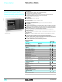
1
Transformer differential protection
Catalogue
January
2002
Sepam 2000 D22 - D32
Merlin Gerin
Contents
Schneider Electric
Presentation
2
Selection table
2
Definitions and general parameters
3
Functions and characteristics
4
Differential protection 87T
4
Differential protection 64 REF
5
Measurements
6
Disturbance recording
7
Control and monitoring
8
Operating mode
9
Program logic Sepam 2000 D22
10
Program logic Sepam 2000 D32
12
Modbus communication
14
General characteristics
15
Installation recommendations
16
Determination of current sensors and settings
16
Dimensions and weights Connections
17
Connection schemes Sepam 2000 D22
18
Two-winding transformer
18
Two-winding transformer with earthed neutral point
19
Two-winding transformer with earthing coil
20
Generator-transformer unit
21
Connection schemes Sepam 2000 D32
22
Three-winding transformer
22
Three-winding transformer with 2 earthed neutral points
23
Three-winding auto-transformer
24
Connection schemes
25
Connection of logical inputs/outputs
25
1
Selection table
The Sepam 2000 D22 and D32 differential
protections are designed to protect
a two-ended or a three-ended zone which
inckudes a transformer, an auto-transformer
or a generator-transformer unit.
Advantages
MT10593.tif
Presentation
Sepam 2000 D22
#
#
#
#
5
5
5
#
5
5
5
5
#
#
#
Complete protection against internal transformer faults.
Restricted earth fault protection included.
Processing of transformer and neutral coil, Buchholz and thermostat data.
Simple implementation due to the use of neural networks:
simplified sizing of current sensors
few settings
no matching transformers required.
Measurement:
primary, secondary currents and phase shifts
residual currents
differential and through currents
memorization of differential and through current at the time of the fault.
Test position.
Disturbance recording.
High level of electromagnetic compatibility (EMC) makes it possible to use digital
technology in electrical substations, without the need for any particular precautions.
# Sepam 2000’s continuous self-testing sets the device in a predetermined fail-safe
position when failures occur, preventing random operation.
# Terminal blocks which may be individually disconnected while energized to
facilitate maintenance.
# Setting and testing are extremely simple. The settings may be made on the front
panel (serial link):
5 one by one, using the TSM2001 pocket terminal, or the SFT2801 PC software
program
5 all at once using the SFT2821 PC software program (downloading).
# The optional communication functions can be used for remote setting of
protections, remote metering, remote annunciation and remote control via a two-wire
link with a supervisor for centralized management.
# ISO 9001 certified design and manufacturing processes.
Selection table
Functions
Protections
Biased differential
Restricted earth fault (winding 2)
Restricted earth fault (winding 3)
Metering
Phase currents I (winding 1)
Phase currents I’ (winding 2)
Phase currents I’’ (winding 3)
Phase shift between I and I’
Phase shift between I and I’’
Residual current Io
Residual current Io’
Residual current Io’’
Differential currents: Id1, Id2, Id3
Through currents: It1, It2, It3
Tripping currents
Sepam types
D22
D32
ANSI code
87T
64REF
64REF
#
#
#
#
#
#
#
#
#
#
#
#
#
#
#
#
#
#
#
#
#
differential: trip Id1, trip Id2, trip Id3
through: trip It1, trip It2, trip It3
Disturbance recording
Control and monitoring
Latching/acknowledgment
86
Annunciation
30
Buchholz and thermostat
Auxiliary 1
Auxiliary 2
External tripping
Detection of plugged connector (DPC) 74
Fault trip counter
Disturbance recording triggering
Sepam 2000 model
S36
Number of ESTOR boards
2
#
#
#
#
#
#
#
#
#
#
#
#
#
#
#
#
#
#
#
#
#
CR
1
CC
2
Schneider Electric
Definitions
and general parameters
Presentation
Définitions
The terms winding 1 and winding 2 are used like that:
# winding 1 refers to the circuit that has the highest voltage Un; the corresponding
currents are connected to connectors 2A and 2B
# winding 2 refers to the circuit that has voltage Un’ less than or equal to Un;
the corresponding currents are connected to connectors 3A and 3B
# winding 3 refers to the circuit that has voltage Un’’ less than or equal to Un’;
the corresponding currents are connected to connectors 4A and 4B.
winding 1
U’, I’ winding 2
Example of
two-winding
transformer:
U= 66 kV,
U’= 11 kV
U, I winding 1
U’, I’
winding 2
Example of
two-winding
auto-transformer:
U= 20 kV,
U’= 15 kV
MT10616.eps
U, I
E61946.eps
E61946.eps
By extension, this definition also applies to an auto-transformer for which 2 windings
are partially combined but which have different voltage level.
U, I
winding 1
U’, I’
winding 2
Example of
three-winding
transformer:
U = 132 kV,
U’ = 33 kV,
U’’ = 11 kV
U’’, I’’
winding 3
U, I winding 1
U’, I’
winding 2
U’’, I’’
winding 3
Example of
three-winding
auto-transformer:
U = 20 kV,
U’ = 15 kV,
U’’ = 6 kV
The zone protected by Sepam 2000 D22 is the zone between the current sensors
connected to connectors 2A and 2B, at one end, and the sensors connected to
connectors 3A and 3B at the other end.
The zone protected by Sepam 2000 D32 is the zone between the current sensors
connected to connectors 2A and 2B at one end, and the sensors connected to
connectors 3A, 3B, 4A and 4B at the other end.
Status menu
Parameters
Selection
Remote reading:
function code and unit
D5h - Hz
D0h - A
D9h - A
DAh - A
D2h - index (4)
D2h - A
DBh - index (4)
DBh - A
DFh - index (4)
DFh - A
DEh
Frequency Fn
50 or 60 Hz
Phase CT ratio winding 1 In
10 to 6250 A
Phase CT ratio winding 2 In’
10 to 6250 A
Phase CT ratio winding 3 In’’ (1)
10 to 6250 A
Type of residual current sensor winding 1
TC + CSH30
Rated residual current winding 1 Ino
1 to 6250 A
Type of residual current sensor winding 2
TC + CSH30
Rated residual current winding 2 Ino’
1 to 6250 A
TC + CSH30
Type of residual current sensor winding 3 (1)
Rated residual current winding 3 Ino" (1)
1 to 6250 A
Numerical index’ of vector group
0 to 11 (2)
(winding 2 versus winding 1)
DEh
Numerical index" of vector group
0 to 11 (2)
(winding 3 versus winding 1)
1 to 999 MVA
DEh - MVA
Rated power of the transformer S (3)
Rated voltage winding 1 Un
220 V to 800 kV DEh - V
Rated voltage winding 2 Un’
220 V to 800 kV DEh - V
Rated voltage winding 3 Un"
220 V to 800 kV DEh - V
(1) Sepam 2000 D32.
(2) Whatever the star or delta connections of the windings.
(3) S refer to the rated power of the transformer in case of two-winding transformer.
S refer to the winding of highest power in case of three-winding transformer.
(4) Meaning of the index :
2
: TC + CSH30
other value
: not used.
Schneider Electric
3
Differential protection
ANSI 87T code
E61950.eps
Functions
and characteristics
Id/Ib
Operation
Id / It = 50 %
This protection adjusts the current phase and module of each winding according to
the parameterized transformer connection. It then compares the adjusted currents,
phase by phase. It is activated if the difference in currents Id for at least one phase
is greater than the operation set point.
The set point is defined by the operation characteristic below.
Protection stability with respect to external faults is also ensured by the biased
characteristic and by the 2nd and 5th harmonics neural network restraint which
analyzes the percentage as well as the differential and through currents.
This restraint prevents unwanted tripping when:
# the transformer is switched on
# an asymmetrical fault occurs outside the zone, causing saturation of
the current transformers
# the transformer is supplied by excessive voltage (overfluxing).
4
tripping
3
Id / It = 15 %
2
setting zone
1
no tripping
0.3
It/Ib
0
2
4
6
8
10
Percentage operation characteristics
S
= transformer rated current
Un
I1’’(1)
87T
I2
I2’
→
→
Id = Iadjusted -I’adjusted = differential current
I2’’ (1)
→
→
It = max ( Iadjusted , I’adjusted ) = through current
It
Id/It > (Id/It %)
Id
Id > 0.3 Ib
F601/1
I1’
I3
I3’
&
tripping
Id(H2)
Id(H5)
≥ 1 F601/4
phase 2
phase 2
tripping
phase 3
E48824.eps
K861
I1’
F601/2
phase 3
I3’’ (1)
Sepam 2000 D32:
phase 1
restraint
element
I1’
I1
phase 1
I1
amplitude and phase adjustment
E61949.eps
Sepam 2000 D22:
E56448.eps
Schematic diagram
tripping
F601/3
F601/6
test mode
(1) D32 application
I1
I1"
Characteristics
Function number
F601
Bias characteristic ID/It
Setting
87T
→
→
→
Id = Iadjusted -I’adjusted -I’’adjusted = differential current
→
→
→
It = max ( Iadjusted , I’adjusted , I’’adjusted )
= through current
15 to 50%
Resolution
1%
Accuracy (1)
±1%
% drop-out
(86 ±10)%
Mini. setting
Value
0.3 Ib
Accuracy (1)
±5%
% drop-out
(90 ±3)%
Time characteristics
Operating time
< 35 ms
Reset time
< 35 ms
Outputs available for control logic
Phase 1 tripping
F601/1
Phase 2 tripping
F601/2
Phase 3 tripping
F601/3
Phase 1, 2 or 3 tripping
F601/4
Test mode
F601/6
Remote reading, remote setting
Function n°
60 h
Parameter
Id/It
unit: %
(1) In reference conditions (IEC 60255-13).
4
Schneider Electric
Differential protection
ANSI code 64 REF
Functions
and characteristics
E61953.eps
Operation
Ido / ln
Ido
Iro
Iso
0.8
Restricted earth fault protection detects phase-to-earth faults in a winding of a
transformer, with an earthed neutral.
It offers the advantage of having greater sensitivity than differential protection.
The function is based on a comparison of the residual current Io ( Io = I1 + I2 + I3 )
and the neutral current Ineutral.
It picks up if the module of the difference Io-Ineutral is greater than the operating set
point. This set point is defined by, first, a minimum Iso set point and, secondly, by a
percentage type tripping characteristic with a slope of 1.05 and an Ino restraint
current characteristic in normal conditions (see curve).
= 1.05
Iso setting zone
ro = l1 + l2 + l3
The sensitivity of the protection is determined by the phase current sensors with a
minimum Iso set point of 5% In.
The protected zone is between the phase CTs and neutral CT.
Iro / ln
0.05
Operation characteristics
In: phase CT rating
Stability with external faults
When an external fault is detected, the restraint current becomes equal to:
2 * ( l1 + l2 + l3 ) + lo ⁄ 3
This makes the protection insensitive to current transformer saturation without
inhibiting its operation.
I3
I neutral
I2
I1
E61952.eps
E61951.eps
Schematic diagram
64 REF
Characteristics
Function number
F651-F661 (2)
Iso setting
Setting
0.05 In to 0.8 In if In 4 20 A
Resolution
1 A ou 1 digit
0.1 In to 0.8 In if In < 20 A
Accuracy (1)
±5% or ±0.5% In
% drop-out
(93 ±5) %
Min. reserve difference
min. 0.4% In
Biased characteristic Ido/Io
Fixed value
1.05
Accuracy (1)
±2%
Time characteristics
Operating time
< 40 ms
Memory time
< 25 ms
Fault recognition time
< 25 ms
Reset time
< 40 ms
Outputs available for control logic
Instantaneous tripping, 64 REF winding 2
F651/1
Instantaneous tripping, 64 REF winding 3 (2)
F661/1
Remote reading, remote setting
Function code
Parameter
F651
65h
F661 (2)
66h
Threshold Iso
unit: 1A
(1) In reference conditions (IEC 60255-13).
(2) D32 application
Schneider Electric
5
Functions
and characteristics
Measurements
Measurements used for commissioning and maintenance
Used to check current transformer connection and for testing.
Phase current
Measurement of current for each of the three phases of each winding.
Measurement of phase shift with respect to the primary current for each
of the phases.
Residual current
Measurement of Io current for each winding.
Differential and through current
Display of the differential and through currents for each of the three phases,
calculated by the differential protection, expressed in primary rms amps.
Tripping currents
Display of the value of the differential and through currents for each of the three
phases, which was stored when the differential protection gave the tripping order,
expressed in primary rms amps.
Characteristics
Measurements
Phase current
Phase shift
Residual current Io
Differential currents Id1, Id2, Id3
Through currents It1, It2, It3
Tripping currents:
Differential: trip Id1, trip Id2, trip Id3
Through: trip It1, trip It2, trip It3
(1) in reference conditions (IEC 60255-13)
Ranges
0 to 24 In
0 to 359°
0 to 10 Ino
0 to 24 In
0 to 24 In
Accuracy (1)
± 0.5% at In
± 3° at In
± 5%
± 5%
± 5%
0 to 24 In
0 to 24 In
± 5%
± 5%
The measurements are available directly in the appropriate units (A, kA) on Sepam
via the console.
6
Schneider Electric
Disturbance recording
Operation
Principe
Used to record analog signal and logical states.
Record storage is triggered by a triggering event:
# tripping of differential protection
# tripping of restricted earth fault protection
# local manual triggering
# remote manual triggering.
The duration of the signal recorded before the
triggering event may be set using the pocket terminal
via the oscillography item in the status menu.
The date of record storage may also be accessed via
the pocket terminal in the oscillography item of the
status menu and via the communication link (refer to
“Jbus/Modbus communication” document). This date
corresponds to the date of the triggering event.
The stored event begins before the triggering event and
continues afterwards.
E61954.eps
Functions
and characteristics
stored record
time
triggering event
Characteristics
Record duration
Record content
Analog signals recorded
Logical states recorded
The record includes of the following informations:
# values sampled from the different signals
# the date
# the characteristics of the recorded channels.
Number of records stored
File format
The files are recorded in FIFO (First In First Out) type
shift storage: the oldest record is erased when a new
record is triggered.
86 periods
the duration before the triggering event may be set
from 1 to 85 periods.
set-up file: date and channel characteristics
data file: 12 values per period/recorded signal
all currents connected to the acquisition boards
tripping outputs O1, O2 and O21,
differential and restricted earth fault operation
digital inputs, I11 to I18
2
COMTRADE IEEE C37.111 - 1997
IEC 60255-24
Restitution
Files may be transferred locally or remotely:
# locally: using a PC which is connected to the console
connector and has the SFT2801 software package
(version later than 9802),
# remotely: using a software package specific to the
remote monitoring and control system.
Record signals may be restituted using the SFT2826 software program.
E56443.tif
Transfer
Example of the processing of a disturbance recording record
using the SFT2826 PC software program.
Schneider Electric
7
Functions
and characteristics
Control and monitoring
MT10594.eps
Latching / acknowledgment (ANSI 86)
Memorizes tripping orders (latching) and requires user action to be put back into
service (reset).
Annunciation (ANSI 30)
Informs the user by means of a message which appears on the display unit.
Indications
Sepam 2000
D32
D22
Alarms
Buchholz
Thermostat
Auxiliary 1
Auxiliary 2
#
#
#
#
Fault detection
Differential
Secondary restricted earth fault
#
#
Tertiary restricted earth fault
Buchholz
Thermostat
Auxiliary 1
Auxiliary 2
#
#
#
#
External tripping
#
#
#
#
Inhibition of differential protection
Operating mode: test connection, inhibition of outputs
#
#
Detection of plugged connectors (DPC) (ANSI 74)
Indication on the display unit that one or more connectors are not plugged in
(the DPC connections must be made: see connection diagrams).
Buchholz and thermostat (D22 application)
Processes faults detected by the Buchholz and thermostat devices integrated in
the equipment: alarm, tripping and indication.
Auxiliary 1, auxiliary 2 (D22 application)
Processes faults detected by the auxiliary devices, such as Buchholz or thermostats
or integrated in the on-load tap changer and neutral earthing: alarm, tripping and
indication.
External tripping (D32 application)
Input available to the Sepam to take into account a process fault detected by an other
device: tripping an indication.
Fault trip counter
Counts the number of trips due to faults detected by the protections or other devices
(Buchholz, auxiliary 1, auxiliary 2) to facilitate equipment maintenance.
Disturbance recorder triggering
Triggers the recording of electrical signals and logical states:
# manualy by local or remote action
# automatically by differential and restricted earth fault protections functions.
Triggering may be locked in order to transfer disturbance records from Sepam 2000
to a PC.
Recording is unlocked by reactivating automatic or manual triggering.
8
Schneider Electric
E61957.eps
Functions
and characteristics
normal
protection
testing and
tripping inhibited
Operating mode
Several operating modes are available to facilitate maintenance and
commissioning operations.
The change from one mode to the other is obtained by means of KP6 and KP9
parameter settings (1).
Normal
The protection functions operate on tripping and signalling contacts according
to the settings.
This mode is the normal operation mode.
tripping
inhibition
protection
testing and
tripping active
Tripping inhibition
The protection functions operate on signalling contacts according to the settings.
The tripping output contacts are inhibited.
This mode is designed to test Sepam 2000 when the protected equipment is still
on duty.
Test mode and tripping inhibited
The protection functions operate on signalling contacts according to the
"test mode settings" (1).
The tripping contacts are inhibited.
This mode is designed to facilate the test of Sepam when the protected equipment
is still on duty.
Test mode and tripping active
The protection functions operate on tripping and signalling contacts according to the
"test mode settings" (1).
This mode is designed to facilate the test of Sepam 2000 including actuators and
wiring. The protected equipment is not on duty.
(1) See "Installation and user’s manual".
Schneider Electric
9
Functions
and characteristics
Program logic
Sepam 2000 D22
MT10617.eps
Grouping of alarms
MT10618.eps
Breaking devices tripping
(1) Tripping inhibition by test mode or by KP setting
Outputs O1 and O2 are dedicated to the tripping of transformer windings 1 and 2
breaking devices.
Outputs O12 and O13 are dedicated to tripping indication.
Time delay T1 is used to calibrate the minimum operating duration of outputs
O1 and O12 associated with winding 1 tripping.
Time delay T2 is used to calibrate the minimum operating duration of outputs
O2 and O13 associated with winding 2 tripping.
Parameter KP13 = 1 latches outputs O1 - O2 - O12 - O13.
Acknowledgment is carried out by pressing “reset”. Output O11 is dedicated to
alarms. It is not a latching relay. Output O14 is dedicated to transformer differential
function indication. It is not a latching relay.
Input I18, associated with the Buchholz device, triggers windings 1 and 2 tripping.
Input I16, associated with the thermostat device, triggers winding 2 tripping.
Parameter KP10 affects winding 2 tripping logic via inputs I2 and I14 associated with
the auxiliary 1 and auxiliary 2 devices:
# winding 1 tripping if KP10 = 0
# windings 1 and 2 tripping if KP10 = 1.
The "trip" indicator needs to be reset, whatever the parameter setting.
10
Schneider Electric
Program logic
Sepam 2000 D22
Functions
and characteristics
Operation
Functions
Differential
Restricted earth fault
Control
Indication
O1
O2
winding 1
winding 2
#
#
#
#
#
#
#
(1)
Message
#
#
#
#
#
#
REF
#
BUCHHOLZ
#
TR.TEMP
#
#
#
(1)
TR.TEMP
AUX .1
#
#
(1)
#
#
(1)
#
#
#
(1)
DIFF.
BUCHHOLZ
#
Auxiliary 2 alarm
Auxiliary 2 tripping
O14
#
Auxiliary 1 alarm
Auxiliary 1 tripping
O13
#
Thermostat alarm
Thermostat tripping
O12
#
Buchholz alarm
Buchholz tripping
O11
AUX .1
AUX .2
Detection of plugged connectors
AUX .2
CONNECTOR
(1) According to parameter setting.
Parameter setting
Parameters KP can be set by means of the console
Functions
Parameter
Tripping control
Winding 1 with shunt trip coil
KP1 = 0
Winding 1 with undervoltage release coil
KP1 = 1
Winding 2 with shunt trip coil
KP2 = 0
Winding 2 with undervoltage release coil
KP2 = 1
Operating functions
Inputs I15 - I16 - I17 - I18 activated
normally closed contact
KP5 = 0
if fault detected by Buchholz / thermostat devices
normally open contact
KP5 = 1
Inputs I1 - I2 activated
normally closed contact
KP7 = 0
if fault detected by auxiliary 1 device
normally open contact
KP7 = 1
Inputs I13 - I14 activated
normally closed contact
KP8 = 0
if fault detected by auxiliary 2 device
normally open contact
KP8 = 1
Aux. 1 (I2) and Aux. 2 (I14) activate winding 1 (upstream) tripping
KP10 = 0
Aux. 1 (I2) and Aux. 2 (I14) activate windings 1 and 2 tripping
KP10 = 1
Latching of outputs associated with tripping O1 - O2 - O12 - O13
KP13 = 1
Operating mode
Switching to test mode
KP6 = 1
Inhibition of differential and restricted earth fault tripping
KP9 = 1
Counter
Resetting of fault trip counter
KP20 = 1
Disturbance recording
Lock triggering
KP50 = 1
Automatic unlock and triggering
KP51 = 1
Manual unlock and triggering
KP52 = 1
Remote setting
Remote setting enable
KP38 = 0
Remote setting disable
KP38 = 1
Schneider Electric
11
Functions
and characteristics
Program logic
Sepam 2000 D32
MT10619.eps
Breaking devices tripping
(1) Tripping inhibition by test mode or by KP setting
(2) Tripping inhibition as the former one, but held during 2 Sepam cycles after the end of the tripping inhibition setting
(see "Installation and user’s manual").
Outputs O1, O2 and O21 are dedicated to the tripping of transformer windings 1,
2 and 3 breaking devices.
Outputs O12, O13 and O22 are dedicated to tripping indication.
Time delay T1 is used to calibrate the minimum operating duration of outputs
O1 and O12 associated with winding 1 tripping.
Time delay T2 is used to calibrate the minimum operating duration of outputs
O2, O13, O21 and O22 associated with windings 2 and 3 tripping.
Acknowledgment is carried out by pressing "reset".
Output O14 is dedicated to transformer differential function indication. It is not a
latching relay.
Parameter KP10 affects windings 2 and 3 tripping logic via input I2 associated with
the external tripping signal.
# Winding 1 tripping if KP10 = 0.
# Windings 1,2 and 3 tripping if KP10 = 1.
The "TRIP" indicator needs to be reset, whatever the parameter setting.
Nota :
# the operating of the winding 2 it the same as the operating of the winding 3 (if one trips,
the other does it too)
# the winding 1 breaking device is with shunt trip coil. The windings 2 and 3 breaking devices
may be setted with shunt trip coil or with undervoltage release coil.
12
Schneider Electric
Program logic
Sepam 2000 D32
Functions
and characteristics
Operation
Functions
Differential
Restricted earth fault winding 2
Restricted earth fault winding 3
External tripping
Control
Indication
O1
O2
O21
O12
O13
winding 1
winding 2
winding 3
winding 1
winding 2
#
#
#
#
#
#
#
5
#
#
#
5
#
#
#
#
#
#
#
5
(1)
(1)
O14
Message
winding 3
#
#
#
(1)
O22
#
#
#
5
DIFF.
REF 2
REF 3
(1)
Detection of plugged connectors
EXT. TRIP.
CONNECTOR
(1) According to parameter setting.
Parameter setting
Parameters KP can be set by means of the console
Functions
Parameter
Tripping control
Winding 2 with shunt trip coil
KP2 = 0
Winding 2 with undervoltage release coil
KP2 = 1
Winding 3 with shunt trip coil
KP3 = 0
Winding 3 with undervoltage release coil
KP3 = 1
Operating functions
Input I2 activated if fault detected by auxiliary device (external tripping)
normally closed contact
KP7 = 0
normally open contact
KP7 = 1
External tripping (I2) activates winding 1 (upstream) tripping
KP10 = 0
External tripping (I2) activates windings 1, 2 and 3 tripping
KP10 = 1
Latching of outputs associated with tripping O1 - O2 - O12 - O13 - O21 - O22
KP13 = 1
Operating mode
Switching to test mode
KP6 = 1
Inhibition of differential and restricted earth fault tripping
KP9 = 1
Counter
Resetting of fault trip counter
KP20 = 1
Disturbance recording
Lock triggering
KP50 = 1
Automatic unlock and triggering
KP51 = 1
Manual unlock and triggering
KP52 = 1
Remote setting
Remote setting enable
KP38 = 0
Remote setting disable
KP38 = 1
Schneider Electric
13
Functions
and characteristics
Modbus communication
Introduction
List of available data
The communication option can be used to connect
Sepam 2000 to a remote monitoring and control system
equipped with a communication channel.
Sepam can be equipped with the Jbus/Modbus
communication option. It is a master-slave protocol with
RS485 and with 2-wire physical link
(300 to 38400 baud rate).
Remote indications
Adresses
Logic input status
Logic output status
Fault trip counter
C2
Sepam not reset (after fault)
Remote control validation report
KTS5
Differential
KTS15
Buccholz alarm
KTS17 (1)
KTS14
Remote reading of settings
Buchholz tripping
KTS18 (1)
The Jbus/Modbus communication option can be used
for remote reading of the following information:
# general characteristics
# protection settings
# status and settings of all control logic resources.
Thermostat alarm
KTS19 (1)
Thermostat tripping
KTS20 (1)
Auxiliary 1 alarm
KTS21 (1)
Remote setting
The Jbus/Modbus communication option can be used
for remote modification of the following parameters:
# protection settings
# control logic time delay set points.
Time-tagging
The communication option can be used for accurate
dating of all remote indications (1).
(1) See "Jbus/Modbus communication" manual, article 75757
Auxiliary 1 tripping
KTS22 (1)
External tripping
KTS22 (2)
Auxiliary 2 alarm
KTS23 (1)
Auxiliary 2 tripping
KTS24 (1)
Restricted earth fault winding 2
KTS25
Restricted earth fault winding 3
KTS26 (2)
Inhibition
KTS30
Test
KTS31
Inhibited disturbance recording (lock triggering)
KTS50
Remote setting inhibited
KTS51
Remote control orders
Acknowledgment of messages
label
KTC35
Inhibition disturbance recording lock triggering
KTC50
Automatic unlock and triggering of disturbance recording
KTC51
Manual unlock and triggering of disturbance recording
KTC52
Remote reading - remote setting
Parameters (reading only)
Protections settings
Control delay settings
(1) D22 application
(2) D32 application
14
Schneider Electric
Functions
and characteristics
General characteristics
Electrical characteristics
Analog inputs
Current transformer
1 A CT
< 0.001 VA
10 A to 6250 A ratings
5 A CT
< 0.025 VA
Voltage
24/30 Vdc
48/127 Vdc
220/250 Vdc
Consumption
4 mA
4 mA
3 mA
Logic inputs
Auxiliary power supply
DC voltage
24/30 Vdc
48/127 Vdc
220/250 Vdc
Typical consumption
18 W
19.5 W
21 W
Voltage
24/30 Vdc
48 Vdc
125 Vdc
220/250 Vdc
Rated current
8A
8A
8A
8A
400 ms overload
15 A
15 A
15 A
15 A
Making capacity
15 A
15 A
15 A
15 A
DC with resistive load
8A
4A
0.8 A
0.3 A
DC with resistive load
6A
2A
0.4 A
0.15 A
DC at L/R = 40 ms
4A
1A
0.2 A
0.1 A
AC with resistive load
8A
8A
8A
8A
AC with p.f. = 0.3
5A
5A
5A
5A
lLgic outputs (relays)
Breaking capacity:
Environmental characteristics
Electric insulation
Dielectric withstand
1.2/50 µs impulse wave withstand
Climatic withstand
Operation
Storage
Damp heat
Corrosion influence
Mechanical robustness
Degree of protection
Vibrations
Shocks / jolts
Earthquakes
Fire resistance
Electromagnetic compatibility
Radiated fields
Electrostatic discharge
Damped 1 MHz wave
5 ns electrical fast transients/burst
1.2/50ms - 8/20ms surge immunity
IEC 60255-5
IEC 60255-5
2 kV - 1 mn (1)
5 kV (2)
IEC 60068-2-1 and 2
IEC 60068-2-14
IEC 60068-2
IEC 60068-2-3
- 5 °C to + 55 °C
- 5 °C to + 55 °C
- 25 °C to + 70 °C
93% RH at 40 °C
56 days (storage)
10 days (operation)
class I
IEC 60654-4
IEC 60529
IEC 60255-21-1
IEC 60255-21-2
IEC 60255-21-3
IEC 60695-2-1
IP 51
class I
class I
class I
IEC 60255-22-3
IEC 61000-4-3
IEC 60255-22-2
IEC 61000-4-2
IEC 60255-22-1
IEC 60255-22-4
IEC 61000-4-4
IEC 61000-4-5
class X
class III
class III
class III
class III
class IV
class IV
class III
Conducted disturbance emission
EN 55022/CISPR22
Radiated field emission
EN 55022/CISPR22
" &" marking on our product guarantees their conformity to European directives.
(1) except for communication 1.4 kV dc and auxiliary power supply 2.8 kV dc.
(2) except for communication 3 kV common mode, 1 kV differential mode.
(3) EN 50081-1 generic standard.
(4) EN 50081-2 generic standard.
Schneider Electric
front face
glow wire
class B
class B
30 V/m
10 V/m
2 kV differential mode (42 Ω)
1 kV common mode (42 Ω)
with auxiliary power supply (3)
(4)
15
Installation
recommendations
Determination of current sensors
and settings
Implementation, settings
Determination of current sensors
Check:
# connections
# settings of microswitches SW1 and SW2:
5 measurement of phase currents
For transformer differential protection
# The current transformers (CT) used shall be of the 5P20 type.
# The phase CT rating should comply with the following rules:
1 A secondary
#
#
#
#
#
#
5 A secondary
#
0.1 .
#
SW2
#
0.1 .
#
#
#
5 measurement of Io current
TC + CSH30
#
#
0.1 .
S
S
6 In 6 2.5 .
for winding 1
Un
Un
S
6 In’ 6 2.5 .
Un’
S
Un’’
S
Un’
6 In’’ 6 2.5 .
S
Un’’
for winding 2
for winding 3
"S" is the transformer power set in the status menu.
2 winding transformer: S is the rated power.
3 winding transformer: S is power value of the most powerful winding.
In, In’ and In’’ are the ratings of the winding 1, 2 and 3 phase current transformers
respectively.
Un, Un’ and Un’’ are the winding 1, 2 and 3 voltages respectively.
For restricted earth fault protection
For each transformer winding:
# set SW1 to "CT + CSH30".
Set the following using the console:
# general parameters
# control logic parameters
# differential protection percentage set point,
(set a value greater than the amplitude of on-load
tap changer variation).
The 999% setting may be used to inhibit the protection
all the outputs are set to zero.
# The Iso setting of the restricted earth fault protection.
The 999 % setting may be used to inhibit the protection.
All outputs are set to zero.
16
# Stability with external faults is ensured if the phase CT saturation current is greater
than 2.4 times the phase-to-earth fault current and 1.6 times the 3-phase fault
current.
Sensitivity to internal faults is ensured if the neutral CT saturation current is greater
than twice the phase-to-earth fault current.
# The neutral point CT rating should comply with the following rule:
0.1 In 6 neutral point CT rating 6 2 In
with In = phase CT rating of the same transformer winding.
If the phase CT rated current In is sufficiently low (In 6 300 A), the neutral current may
be measured by a CSH120 or CSH200 core balance CT.
If this is not the case (which happens most frequently), the neutral current is
measured by a CT. A CSH30 interposing ring CT is required between the 1 A or 5 A
secondary winding of the neutral CT and the Sepam 2000 residual current input.
Schneider Electric
Dimensions and weights
Connections
Installation
recommendations
E61966.eps
Dimensions and weights
E56468.eps
mounting latches (x2)
222
201
e = 3 mm max
300
MT10662.eps
20
222
352
MT10663.eps
Cut-out
202
338
E56472.tif
Connections
Current transformers
CSH core balance CTs,
CSH 30 adapter
Logic inputs/outputs
Type
Wiring /
cabling
Accessories
reference
Type
screw for
∅4 eye lug
screw
6 6 mm2
CCA660 (1)
connector
6 2.5 mm2
CCA606
(1)
connector
screw
6 2.5 mm2
6 2.5 mm2
CCA621
(1)
connector
CCA604
(1)
connector
Power supply
screw
Jbus/Modbus
communication
9-pin sub-D
connector
CCA602
CCA619
cable (length: 3 m)
with two 9-pin sub-D
9-pin sub-D
connector box
(1) Accessories supplied with Sepam 2000
Sepam 2000 D22 rear face with standard connectors
Schneider Electric
17
Two-winding transformer
The transformer neutral points may or may not be
earthed.
No neutral point CT is necessary for proper operation
of the differential protection.
MT10599.eps
Connection schemes
Sepam 2000 D22
CE40
1B
1
2
3
1A 4
4
1
2B
ECMD
87T
5
2
6
3
ESB 5A 21
DPC
20
CDG
O2
O1
Yy
YNyn
YNy
Yyn
Yd
YNd
Dy
Dyn
l2
l1
19
18
17
16
15
14
13
12
11
10
9
8
7
6
5
4
3
2
1
ESTOR 6A 21
1
4
3B ECMD
1
5
2
6
3
L1 L2 L3
Sepam 2000 D22
DPC: detection of plugged connectors.
CDG: watchdog.
# Correspondence between primary and secondary connections (e.g. P1, S1)
18
Schneider Electric
Two-winding transformer
with earthed neutral point
The transformer primary neutral may or may not
be earthed.
Neutral current measurement on the secondary
winding is essential for correct operation of the
restricted earth fault protection function.
E61959.eps
Connection schemes
Sepam 2000 D22
CE40
1B
1
2
3
1A 4
winding 1
4
1
2B
ECMD
87T
ESB 5A 21
DPC
20
5
2
6
3
19
18
17
16
15
14
13
12
11
10
9
8
7
6
5
4
3
2
1
CDG
O2
O1
Dyn
Yyn
YNyn
l2
l1
2
1
6
5
4
3
2
1
3A
ECMD
DPC
64
REF
30 A
2A
Connection
of a 5 A current transformer
via a CSH30 interposing
ring CT
ESTOR
1
E61960.eps
4
2
1
5 turns
6
5
4
3
2
1
21
CT +
CSH30
Connection of a 1 A current transformer via a CSH30
interposing ring CT.
3A
6A
ECMD
3B
1
5
2
DPC
30 A
2A
CT+ CSH30
winding 2
6
3
L1 L2 L3
Sepam 2000 D22
DPC: detection of plugged connectors
CDG: watchdog
# Correspondence between primary and secondary connections (e.g. P1, S1)
Schneider Electric
19
Two-winding transformer
with earthing coil
The transformer primary neutral may or may not
be earthed.
Neutral current measurement on the secondary
winding is essential for correct operation of the
restricted earth fault protection function.
E61961.eps
Connection schemes
Sepam 2000 D22
CE40
1B
1
2
3
1A 4
winding 1
4
1
2B
ECMD
87T
ESB 5A 21
DPC
20
5
2
6
3
19
18
17
16
15
14
13
12
11
10
9
8
7
6
5
4
3
2
1
CDG
O2
O1
Yd
YNd
l2
l1
Connection of a 5 A current
transformer via a CSH30
interposing ring CT
ESTOR
2
Connection of a 1 A current transformer via a CSH30
interposing ring CT.
E61962.eps
1
6
5
4
3
2
1
4
6
5
4
3
2
1
2
1
5 turns
3A
3A
ECMD
DPC
64
REF
6A
21
1
30 A
2A
CT +
CSH30
3B
1
5
2
ECMD
DPC
winding 2
30 A
2A
CT+ CSH30
6
3
L1 L2 L3
Sepam 2000 D22
DPC: detection of plugged connectors
CDG: watchdog
# Correspondence between primary and secondary connections (e.g. P1, S1)
20
Schneider Electric
Generator-transformer unit
MT10602.eps
Connection schemes
Sepam 2000 D22
L1
L2
L3
CE40
1B
1
2
3
1A 4
4
1
2B
ECMD
87T
ESB 5A 21
DPC
20
5
2
6
3
19
18
17
16
15
14
13
12
11
10
9
8
7
6
5
4
3
2
1
CDG
O2
O1
Yy
YNy
Yyn
Yd
YNd
Dy
Dyn
l2
l1
ESTOR
6A
21
1
4
3B
ECMD
1
5
2
6
3
Sepam 2000 D22
DPC: detection of plugged connectors
CDG: watchdog
# Correspondence between primary and secondary connections (e.g. P1, S1)
Schneider Electric
21
Three-winding transformer
No neutral point CT is necessary for proper operation
of the differential protection.
MT10603.eps
Connection schemes
Sepam 2000 D32
L1 L2 L3
CE40
1B
1
2
3
1A 4
4
1
2B
ECMD
87T
ESB 5A 21
DPC
20
5
2
6
3
19
18
17
16
15
14
13
12
11
10
9
8
7
6
5
4
3
2
1
CDG
O2
O1
l2
l1
4
ESTOR
3B
1
5
2
6A
ECMD
21
6
3
L1 L2 L3
1
ESTOR
7A
21
1
ESTOR
4
1
5
2
4B
8A
21
ECMD
6
3
1
L1 L2 L3
Sepam 2000 D32
DPC: detection of plugged connectors
CDG: watchdog
# Correspondence between primary and secondary connections (e.g. P1, S1)
22
Schneider Electric
Three-winding transformer
with 2 earthed neutral points
The neutral point current measurements are necessary
for restricted earth fault protections.
MT10620.eps
Connection schemes
Sepam 2000 D32
L1 L2 L3
CE40
1B
1
2
3
1A 4
4
1
2B
ECMD
87T
ESB 5A 21
DPC
20
5
2
6
3
19
18
17
16
15
14
13
12
11
10
9
8
7
6
5
4
3
2
1
CDG
Connection of a 5 A
current transformer
via a CSH30
interposing ring CT
O2
O1
2
1
6
5
4
3
2
1
3A
ECMD
DPC
64
REF
l2
l1
30 A
2A
CT +
CSH30
ESTOR
4
6A
21
3B
1
5
2
6
3
1
L1 L2 L3
Connection of a 5 A
current transformer
via a CSH30
interposing ring CT
2
6
5
4
3
2
1
4A
ECMD
DPC
2
1
5 turns
6
5
4
3
2
1
3A
ECMD
21
64
REF
CT +
CSH30
1
ESTOR
4
7A
30 A
2A
E61960.eps
Connection of a 1 A current transformer via a
CSH30 interposing ring CT.
1
ESTOR
8A
21
4B
1
5
2
DPC
6
3
30 A
2A
CT+ CSH30
1
L1 L2 L3
Sepam 2000 D32
DPC: detection of plugged connectors
CDG: watchdog
# Correspondence between primary and secondary connections (e.g. P1, S1)
Schneider Electric
23
Three-winding auto-transformer
MT10605.eps
Connection schemes
Sepam 2000 D32
L1 L2 L3
CE40
1B
1
2
3
1A 4
4
1
2B
ECMD
87T
ESB 5A 21
DPC
20
5
2
6
3
19
18
17
16
15
14
13
12
11
10
9
8
7
6
5
4
3
2
1
CDG
O2
O1
l2
l1
4
ESTOR
4B
1
5
2
6A
ECMD
21
6
3
L1 L2 L3
1
ESTOR
4
1
5
2
3B
7A
21
ECMD
6
3
1
ESTOR
8A
21
1
L1 L2 L3
Sepam 2000 D32
DPC: detection of plugged connectors
CDG: watchdog
# Correspondence between primary and secondary connections (e.g. P1, S1)
24
Schneider Electric
Connection schemes
Connection
of logical inputs/outputs
MT10606.eps
ESB board
ESB
Terminals
A
DPC
CDG
O2
O1
l2
l1
21
20
19
18
17
16
15
14
13
12
11
10
9
8
7
6
5
4
3
2
1
21
20
19
18
17
16
15
14
13
12
11
10
9
8
7
6
4
3
2
1
DPC
Connected data
D22 application
D32 application
detection of plugged connectors detection of plugged connectors
CDG
watchdog
watchdog
O2
secondary tripping
secondary tripping
O1
primary tripping
primary tripping
I2
auxiliary 1 tripping
external tripping
I1
auxiliary 1 alarm
reserved
MT10607.eps
ESTOR 1 board
ESTOR
DPC
l18
l17
l16
l15
l14
l13
O14
O13
O12
O11
l12
l11
Terminals
A
21
20
19
18
17
16
15
14
13
12
11
10
9
8
7
6
5
4
3
2
1
Schneider Electric
21
20
19
18
17
16
15
14
13
12
11
10
9
8
7
6
5
4
3
2
1
DPC
I18
I17
I16
I15
I14
I13
O14
O13
O12
O11
I12
I11
Connected data
D22 application
D32 application
detection of plugged connectors detection of plugged connectors
Buchholz tripping
Buchholz alarm
thermostat tripping
thermostat alarm
auxiliary 2 tripping
auxiliary 2 alarm
common
transformer differential or
restricted earth fault indication
indication of winding
2 tripping
indication of winding
1 tripping
alarm: thermostat or Buchholz
or auxiliary 1 or auxiliary 2
remote control authorized
reserved
reserved
reserved
reserved
reserved
reserved
reserved
transformer differential or
restricted earth fault indication
indication of winding
2 tripping
indication of winding
1 tripping
reserved
remote control authorized
reserved for communication
synchronization
reserved for communication
synchronization
25
Connection schemes
Connection
of logical inputs/outputs
MT10608.eps
ESTOR 2 board (D32 application)
ESTOR
DPC
l28
l27
l26
l25
l24
l23
O24
O23
O22
O21
l22
l21
26
A
21
20
19
18
17
16
15
14
13
12
11
10
9
8
7
6
5
4
3
2
1
Terminals
21
20
19
18
17
16
15
14
13
12
11
10
9
8
7
6
5
4
3
2
1
DPC
I28
I27
I26
I25
I24
I23
Connected data
detection of plugged connectors
O24
reserved
reserved
reserved
reserved
reserved
reserved
reserved
reserved
O23
reserved
O22
indication of winding 3 tripping
O21
winding 3 tripping
I22
reserved
I21
reserved
Schneider Electric
Notes
Schneider Electric
27
Notes
28
Schneider Electric
Ordering informations
Sepam 2000
quantity
Sepam type
D22 ........................................................................................................
D32 ........................................................................................................
Option
Communication ......................................................
without ..............................
................................................................................
Jbus/Modbus ....................
Working language...................................................
French ..............................
................................................................................
English ..............................
................................................................................
Spanish ............................
................................................................................
Italian ................................
Auxiliary power supply ...........................................
24/30 Vdc .........................
................................................................................
48/127 Vdc .......................
................................................................................
220/250 Vdc .....................
Accessories
quantity
Pocket terminal.......................................................
TSM2001 .............
Setting software with PC connexion kit ..................
SFT2801 +
SFT2821 ..............
Disturbance recording display software .................
SFT2826 ..............
Interposing ring CT for residual
current input............................................................
CSH30 .................
Jbus/Modbus communication
# 9-pin sub-D connector box .................................. CCA619 ...............
# Jbus/Modbus network connection box ................ CCA609 ...............
# cable (length: 3 m)
with two 9-pin sub-D connectors ............................
CCA602 ...............
Schneider Electric
Industries SA
Postal address
F-38050 Grenoble cedex 9
Tel : +33 (0)4 76 57 60 60
As standards, specifications and designs change from time to
time, please ask for confirmation of the information given in thid
publication.
http://www.schneider-electric.com
PCRED398061EN /2 © 2002 Schneider Electric - All right reserved
# interfaces box RS485/RS232 ............................. ACE909-2 ............
This document has been
printed on ecological paper
Publishing: Schneider Electric SA
Design, production: HeadLines
Printing: Imprimerie des Deux-Ponts
ART.15805
01/2002