1
HP-13009-5
Universal Controller
SCX10
STARTUP MANUAL
Thank you for purchasing an Oriental Motor product.
The SCX10 has been designed to be easy to use, and contains several unique functions.
This startup manual should help you to get to know the product quickly. Please read the separately
supplied operating manual for more detailed information.
■It will be necessary to connect the SCX10 to a computer for initial setup and test operation. Provide a
computer and a commercially available USB mini-B cable.
■The ESMC controller must be set to the driver mode when combining with the SCX10. The ESMC
controller is represented as "driver" in this startup manual.
Chapter 1
Safety Precautions
The precautions described below are intended to prevent danger or injury to the user and other personnel through safe, correct use
of the product. Use the product only after carefully reading and fully understanding these instructions.
Warning
Handling the product without observing the instructions that accompany a "Warning"
symbol may result in serious injury or death.
Caution
Handling the product without observing the instructions that accompany a "Caution"
symbol may result in injury or property damage.
Note
Memo
The items under this heading contain important handling instructions that the user
should observe to ensure safe use of the product.
This contains information relative to the description provided in the main text.
Warning
Caution
General
General
• Do not use the product in explosive or corrosive
environments, in the presence of flammable gases, locations
subjected to splashing water, or near combustibles. Doing so
may result in fire or injury.
• Assign qualified personnel the task of installing, wiring,
operating/controlling, inspecting and troubleshooting the
product. Failure to do so may result in fire or injury.
• Do not transport, install the product, perform connections or
inspections when the power is on. Always turn the power off
before carrying out these operations. Failure to do so may
result in electric shock.
• When the device’s protective function is triggered, first
remove the cause and then clear the protective function.
Continuing the operation without determining the cause of
the problem may cause malfunction of the device, leading to
injury or damage to equipment.
• Do not use the device beyond its specifications, or injury or
damage to equipment may result.
Installation
• Install the device in an enclosure in order to prevent injury.
Connection
• Keep the device’s input-power voltage within the specified
range to avoid fire.
• For the device’s power supply use a DC power supply with
reinforced insulation on its primary and secondary sides.
Failure to do so may result in electric shock.
• Connect the cables securely according to the wiring diagram
in order to prevent fire.
Operation
• Turn off the device power in the event of a power failure, or
the motor may suddenly start when the power is restored and
may cause injury or damage to equipment.
Repair, Disassembly and Modification
• Do not disassemble or modify the device. This may cause
injury. Refer all such internal inspections and repairs to the
branch or sales office from which you purchased the product.
-2-
Transportation
• Do not hold the device cable. This may cause damage or
injury.
Installation
• Keep the area around the device free of combustible
materials in order to prevent fire or skin burn(s).
Connection
• When grounding the positive terminal of the power supply,
do not connect any equipment (PC, etc.) whose negative
terminal is grounded. Doing so may cause the driver and PC
to short, damaging both.
Operation
• To avoid injury, remain alert during operation so that the
device can be stopped immediately in an emergency.
• Before supplying power to the device, turn all start inputs to
the device to "OFF." Otherwise, the device may start
suddenly and cause injury or damage to equipment.
• When an abnormality is noted, stop the operation
immediately, or fire or injury may occur.
Disposal
• When disposing of the device, treat it as ordinary industrial
waste.
Chapter 2
List of Items
• Universal Controller (SCX10)
1 unit
• CD-ROM
1 pc.
(Immediate Motion Creator for CM/SCX Series (utility software), Startup manual, Operating manual,
CANopen EDS file, USB driver, .NET Framework 2.0)
• Connector set
1 set (packed in a bag)
RS-232C connector (3 pins): 1
CANopen connector (4 pins): 1
Power connector (3 pins): 1
• Encoder connector housing/contact (8 pins)
1 set (packed in a bag)
• Startup manual (This manual)
1 copy
-3-
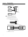
Chapter 3
Preparation
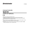
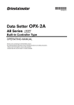
3.1 Connection and Switch Setting
USB
PC
24 VDC
Power supply
+
-
D-SUB 25pin connector
Driver
For all drivers except AR/NX series
1.
2.
Set the driver pulse Input mode to 1 pulse mode.
See the driver manual for information on how to set.
Connect Pulse/Direction signals to the driver connector
Pin assignment for D-SUB 25 pin connector
2: DIR+/CCW+
1: PLS+/CW+
14: PLS-/CW15: DIR-/CCW-
*See the driver manual for pulse input circuit and pin assignment on the driver.
The following example shows photo-coupler pulse input type drivers. (1-pulse mode)
SCX10
1
14
2
15
Memo
3.
-4-
PLS+/CW +
PLS+
PLS-/CW -
PLS-
DIR+/CCW +
DIR+
DIR-/CCW -
DIR-
Driver
The 5/24 V and SOURCE/SINK switch settings are not required for test operation.
After the test operation, set those switches according to the Operating Manual.
Connect the 24 VDC power supply
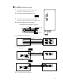
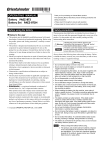
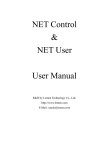
For AR/NX series driver only
Set the driver interface voltage switch to 5 V
5V
3.
4.
24 V
Set the driver interface logic switch as you desire
*Connections differ according to the switch settings as below.
5V 24V SOURCE SINK
2.
Set the driver pulse input mode to 1 pulse mode.
See the driver user manual about how to set.
DRIVER
1.
Connect Pulse/Direction and CON signals
Pin assignment for D-SUB 25 pin connector
13: 5/24 V OUT
6: GND
7: CON
2: DIR+/CCW+
1: PLS+/CW+
14: PLS-/CW15: DIR-/CCW-
• Pulse (PLS)/Direction (DIR) signals
SCX10
1
14
2
15
PLS+/CW+
PLS+
PLS-/CW-
PLS-
DIR+/CCW+
DIR+
DIR-/CCW-
DIR-
Driver
31
32
35
36
• Current ON (CON) signal
a. Sink Logic
SOURCE
SCX10
5V
SINK
5/24 V OUT
13
7
CON
IN-COM
C-ON
Driver
22
23
GND
b. Source Logic
SOURCE
SINK
SCX10
GND
6
7
GND
IN-COM
CON
C-ON
Driver
22
23
5V
5.
Connect the 24 VDC Power supply
-5-
3.2 Preparation of Computer
Install the provided USB driver and utility software to your personal computer in order to execute a test operation or make
initial settings.
Memo
1.
When using RS-232C, skip the installation of the USB driver and go to "2. Installation of Utility Software
Immediate Motion Creator for the CM/SCX Series (IMC)."
Installing the USB Driver
Insert the supplied CD-ROM into the CD-ROM drive of the computer, power on the SCX10 and Connect to a USB port
using a Mini-B cable. (Prepare a commercially available USB mini-B cable.) You will then be asked to install the USB
driver. See the procedure according to the type of Windows as follows.
Windows 7:
1. Open "Devices and Printers " in the control panel.
2. Right click on "FT232R USB UART" and select "Update Driver Software."
3. Select "Browse my computer for driver software."
4. Click "Browse" and select the applicable CD-ROM drive, check the box next to "Include subfolders" and click "Next."
5. After successful installation, click "Close."
6. Go back to the Device Manager, right click on "USB Serial Port" and select "Update Driver Software." Repeat same
procedure as the above FT232R USB UART installation.
Windows Vista:
1. The installation of the FT232R USB UART is asked by Windows when the SCX10 is connected. Select "Locate and
install driver software," and click "Next." After successful installation, click "Close."
2. The installation of the USB Serial Port is then asked for by Windows.
3. Click "Next." After successful installation, click "Close."
Windows XP:
1. The installation of the FT232R USB UART is asked for by Windows when the SCX10 is connected. Select "Install the
software automatically," and click "Next." After successful installation, click "Finish."
2. The installation of the USB Serial Port is then asked for by Windows. Select "Install the software automatically," and
click "Next."
3. After successful installation, click "Finish."
Windows 2000:
1. The "Found New Hardware Wizard" will be launched when the SCX10 is connected. Click "Next."
2. For the FT232 USB UART installation, select "Search for a suitable driver for my device," and click "Next."
3. Check the box next to "Specify a location" and uncheck all others. Click "Next."
4. Click "Browse." Select the applicable CD-ROM drive and click "Open." Locate the "USB_Driver" folder and click
"Open." Click "OK." Click "Next." After successful installation, click "Finish."
5. The installation of the USB Serial Port is then asked by Windows. Repeat same procedure as the above FT232 USB
UART installation. After successful installation, click "Finish."
2.
Installation of Utility Software Immediate Motion Creator for the CM/SCX Series (IMC)
Insert the supplied CD-ROM into your CD-ROM drive. Open the Explorer, select the applicable CD-ROM drive, open the
IMC folder, double click on "setup.exe" and follow the on screen instructions.
*If Windows 2000 or Windows XP is used, it is necessary to install Microsoft .NET Framework 2.0 before installing the
IMC. The .NET Framework 2.0 software is on the supplied CD-ROM, under the DotNet_Framework2_0 folder. Visit the
Microsoft .NET Framework website if detailed information is required.
System Requirements for the IMC
- Windows 2000 SP3 or later, Windows XP SP2 or later, Windows Vista, Windows 7
- .NET Framework 2.0 or later
- SVGA monitor 800 x 600 or greater
- USB or RS-232C port
- CD-ROM drive
System Requirements for .NET Framework 2.0
- Supported Operating Systems: Windows 2000 SP3 or later, Windows XP SP2 or later
- Disk Space: 280 MB
Note
Memo
-6-
After Installation, click "Help" - "Check New Version" on the pull down menu with the Internet
connection. If a newer version of this software is available, continue to the download and update
actions.
When updating the installed version of the IMC, do so when the existing IMC is not running.
Chapter 4
Setting the User Unit
In the SCX10, the actual motion distance of the user application, such as "mm," "inch," "revolution" and "degree" is used,
instead of the pulse unit that is commonly used in pulse generators and motor controllers. This is called "user unit" and is set
initially by the following steps as with the motor resolution.
4.1 Determine Parameters
Three parameters are required to be set.
- Unit that is used in your application (Ex. "Rev,""mm")
- Travel amount per one revolution of the motor shaft (distance per revolution)
- Motor resolution
Referring to the examples shown below determine the unit to a value that is actually used. You can set the indivisible number
as well using the electronic gear (In this case, five parameters are required to be set.). More detail and/or more examples of
settings are shown in "7.3 Setting the User Unit" of the operating manual.
Ex.1) You wish to set the travel distance in "revolution" with a resolution of 1000:
The user unit becomes "Rev," the distance per one revolution becomes 1 and the motor resolution becomes 1000.
Ex.2) You wish to set the travel distance in 0.01 mm increments while using a ball screw with a 10mm lead:
The user unit becomes "mm," the distance per one revolution becomes 10 and the motor resolution becomes 1000 (the
ball screw travels 10 mm per one motor revolution while the motor moves 0.01 mm per one pulse, "10/0.01 = '1000'
pulses per revolution).
Ex.3) When an actuator with ESMC controller (0.01 mm resolution) is used:
The user unit becomes "mm," the distance per one millimeter mm becomes 1 and the motor resolution becomes 100.
(1/actuator resolution = 1/0.01= 100)
Memo
Since the resolution of the actuator/ESMC controller is based on one millimeter while the
resolution of other motors/drivers are based on one revolution. Therefore, the “distance per
revolution” parameter on the SCX10 works as a “distance per millimeter” for the ESMC
controller.
4.2 Setting Resolution of the Driver
Set the motor resolution, using the switch of the driver.
(For NX Series: Set it using the OPX-2A data setter or the MEXE02 data setting software.)
Ex.1)
Set the resolution 1000. (See the operating manual for the driver.)
Ex.2)
Set the resolution 1000. (See the operating manual for the driver.)
Ex.3)
The setting of resolution is not required. The resolution of the ESMC controller is fixed.
-7-
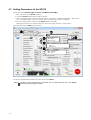
4.3 Setting Parameters of the SCX10
Start up the installed Immediate Motion Creator for CM/SCX Series (IMC).
1. Turn on the power for the SCX10 and driver.
2. Connect the SCX10 mounted using a USB mini B cable.
3. Click in the following order: Click start button in Windows - "Programs" - "ORIENTAL MOTOR" - "IMC for CM
SCX" - "Immediate Motion Creator for CM SCX Series" (COM port select window is displayed)
4. Select the COM port that is connected to the SCX10, and then click [OK].
(Selecting the baud rate is not required at this point. The factory setting, 9600 bps is used to launch.)
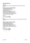
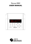
Set the parameter when the IMC has been launched.
②
①
Select the
[System Parameter] tab.
Select the [System Config] tab.
③
④
⑤
Enter the desired unit.
(Ex1:"Rev")
(Ex2, 3:"mm")
⑥
Click [SAVE and RESET]
to enable the parameters.
Enter the distance per a motor revolution.
(Ex1: 1)
(Ex2, 3: 10)
Enter the motor resolution.
(Ex1, 2: 1000)
(Ex3: 100)
The setting is completed. The parameters have been written to the SCX10.
Memo
-8-
The setting can also be made using commands. See "7.3 Setting the User Unit " in the SCX10
operating manual (supplied CD-ROM).
Chapter 5
Test Operation
Let's try to operate a motor/an actuator and confirm that the use unit is correctly set. After confirming that there is no danger
in the surrounding area even when the motor/actuator starts running suddenly, operate it according to the following
procedures.
5.1 Test Operation by "Motion Creator" Function of the IMC
At first, let’s check the unit for motion parameters. Click the "Motion Creator" tab on the IMC window. The units for motion
parameters are shown according to the user unit (ex. if the "mm" has been set, the unit for distance should have become
"mm" and the unit for velocity should have become "mm/sec.")
Operate the motor/actuator according to the following instruction when the IMC has been launched.
②
①
Select the [Motion Creator] tab.
Other than AR, NX: Check if
the [Current] LED picture is
green (the motor is excited)
③
Select [Incremental].
④
AR/NX: Click the [Current]
button. The LED turns green.
(Motor is now excited.)
Change the value in the area for
"Distance.".
(Ex1: 1)
(Ex2, 3: 10)
⑤
Click the [START Motion] button
while looking at the motor shaft or
actuator.
Did the motor/actuator move according to what you set?
Ex.1) The motor shaft should rotate one revolution in the clockwise direction.
Ex.2) The motor shaft should rotate one revolution in the clockwise direction and the ball screw should travel 10 mm if
the ball screw is connected. (Since a ball screw with a lead of 10 mm/rev is assumed, the motor shaft should rotate
one revolution when setting to 10 mm in "Distance")
Ex.3) The actuator starts to move in the forward direction, and will move 10 mm.
Add a "minus (-)" in front of the value in "Distance," and then click the [START Motion] button again. This time, the
motor/actuator should move the same distance in opposite direction and then stop. Change distance, velocity, acceleration
and deceleration time, and see difference in motions.
Now, look at the command syntax area in the lower left of the screen.
You can see the letters such as DIS 1, VS 0.1, VR 1 and others. These are the commands that are actually sent to the SCX10.
For instance, the travel amount is "DIS" (abbreviation for Distance), the starting velocity is "VS" (abbreviation for Velocity
for Start) and the running velocity is "VR" (abbreviation for Velocity for Running). Each line corresponds to the operation
parameter that was input in ④. "MI" in the last line is abbreviation for Move Incremental, which is the command for
starting an operation. The IMC sends the command to the SCX10 on behalf of you.
Let's try executing these commands in the next page.
-9-
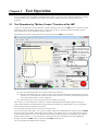
5.2 Test Operation by Command Input
Here, let us introduce how to command an operation by directly communicating with the SCX10. First, click the [Terminal]
tab and open the terminal screen. (An operation by commands can be executed using commercially available terminal
software as well.)
Try to input commands according to the following procedures.
For example, you have set user unit parameters with the Ex.1
1. Check that the motor current is ON / Set the motor current ON
<For all drivers except AR/NX Series>
<For AR/NX Series>
Enter "CURRENT," and press the Enter key.
Enter "CURRENT=1," and press the Enter key.
(A space can be used and replaced with an equal sign
between command and parameter.)
>CURRENT
CURRENT=1
When pressing the Enter key, "CURRENT=1" is displayed
in the next line. This is a message that the SCX10
responded. It shows "CURRENT" command that you
typed was accepted and the CURRENT parameter of the
SCX10 is "1" (the motor current is ON).
If "CURRENT=0" is indicated, the motor current is OFF.
Enter "CURRENT=1," and press the Enter key. The
response with "CURRENT=1" will be displayed and the
motor current will be ON.
>CURRENT=1
CURRENT=1
When pressing the Enter key, "CURRENT=1" is
displayed in the next line. This is a message that the
SCX10 responded. It shows "CURRENT=1" that you
typed was accepted and the CURRENT parameter of the
SCX10 was set to "1" (the motor current is turned ON).
When checking the currently set value of a parameter is
desired, type only the command ("CURRENT" in this
case) and press the Enter key. The parameter that is set to
the SCX10 will be displayed.
2. Set the move distance
Enter "DIS=10," and press the Enter key.
(A space can be used and replaced with an equal sign between command and parameter.)
>DIS=10
DIS=10 Rev
3. Set the running velocity
Enter "VR=1," and press the Enter key.
>VR=1
VR=1 Rev/sec
4. Make the motor move
Enter "MI," and press the Enter key.
>MI
>
The motor starts to move in clockwise direction, and will rotate 10 revolutions at 1 rev/sec.
Were you able to operate the motor properly? Let’s change some conditions and operate them.
- 10 -
Ex.1) Invert the direction: Enter "DIS= -10," and press the Enter key. Enter "MI," and press the Enter key. The motor
starts to move in reverse direction, and will rotate 10 revolutions at 1 rev/sec.
Ex.2) Change the running velocity: Enter "VR=2," and press the Enter key. Enter "MI," and press the Enter key. The
motor starts to move at 2 rev/sec.
Ex.3) Absolute motion: Check the motor position (value) displayed in the lower right of the IMC window. This is the
current position command that is the distance from the position when the power is turned on. As a trial, enter "MA
10," and press the Enter key. The motor position should move to "10.000" and stop regardless of the current
position.
Setting the Baud Rate
Chapter 6
Use of the USB communication at a baud rate as high as possible (115200 bps if no problem occurs during communication)
is recommended for operating the IMC. The operation response speed for launching, tab screen change, parameter settings
will be improved. Set the baud rate to the SCX10 according to the following steps.
1. Turn on the power for the SCX10, connect to the computer.
2. Launch the IMC.
3. Click the [System Config] tab.
4. Click the "USB Baud rate" located at the upper-center, and select "115200 bps" from the drop-down list.
(For an operator using RS-232C, set the "RS232 Baud rate.")
5. Click the [SAVE and RESET] to enable the change. At that time, the IMC also changes the baud rate of computer side to
115200 bps. (The SCX10 is already communicating with your computer at 115200 bps.)
Note
When starting communication with the SCX10, be sure to set the baud rate of the IMC to the same
baud rate that has been set to the SCX10. If you are unsure about the baud rate of the SCX10, use
the "Scan Baud Rate" button on the Serial Port Settings window. If the wrong baud rate has been set
in the Serial Port Settings window, not only will the communication not be established, but it may also
be possible that the communication will never be established even if the baud rate is correctly set
afterwards. If this communication problem occurs, turn off the power to the SCX10, wait for a few
seconds and restart. Take the same action when communication is likely to be disconnected.
Features
Chapter 7
7.1 Features of the SCX10
The SCX10 can be used with ease, in addition, the SCX10 can perform most operations that you can imagine with a feature
rich interface and functions.
See below in the operating manual (in supplied CD-ROM) for instructions.
-
For motion types and features: "Chapter 8 Features"
For executing sequences: "Chapter 9 Program Creation and Execution"
For CANopen communication: "Chapter 10 Control by CANopen Communication"
Other functions that has not been explained in above: "Appendix C TIPS"
- 11 -
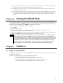
7.2 Support of Driver Functions
The SCX10 can be performed most of the drivers' functions and signals for I/O using commands. The connection and signals
are explained in "6.5 connecting the Driver" of the operating manual and the settings are explained in "7.5 Optional Settings for
Driver" of the operating manual. Also, the following specific functions are explained in the section on the individual page.
For AR Series driver (AC and DC input type)
- If the push motion operation is required, see "8.4 Torque Limiting/Push-motion Operation"
For NX Series driver
- If the torque limiting operation is required, see "8.4 Torque Limiting/Push-motion Operation"
- If the current position reading is required, see "8.3 Driver Current Position Reading"
- If the accurate return-to-mechanical home operation is required such as using the Z-phase signal (timing
signal), see "HOMEDCL (deviation counter clear select at mechanical home seeking operation)" section in
"8.2.5 Mechanical Home Seeking"
For ESMC controller
- If the current position reading function is required, see "8.3 Driver Current Position Reading"
- If the sensor-less mechanical home seeking operation is required, see "Sensorless Mechanical Home
Seeking Operation for HOMETYPE=12" section in "8.2.5 Mechanical Home Seeking"
Settings for the SCX10 and driver are required to change when using above functions since some necessary signals are not
assigned to the driver I/Os with the factory setting. See "6.5.3 Change of Signal Assignment."
• Please contact your nearest Oriental Motor office for further information.
Technical Support Tel:(800)468-3982
8:30 A.M. to 5:00 P.M., P.S.T. (M-F)
7:30 A.M. to 5:00 P.M., C.S.T. (M-F)
E-mail: [email protected]
www.orientalmotor.com
Headquarters and Düsseldorf Office
Tel:0211-52067-00
Fax:0211-52067-099
Munich Office
Tel:089-3181225-00 Fax:089-3181225-25
Hamburg Office
Tel:040-76910443
Fax:040-76910445
Tel:400-820-6516
Fax:021-6278-0269
Tel:(02)8228-0707
Fax:(02)8228-0708
Tel:+65-6745-7344
Fax:+65-6745-9405
Tel:01256-347090
Fax:01256-347099
Tel:(03)22875778
Fax:(03)22875528
Tel:01 47 86 97 50
Fax:01 47 82 45 16
Tel:+66-2-251-1871
Fax:+66-2-251-1872
Tel:02-93906346
Fax:02-93906348
KOREA
Tel:080-777-2042
Fax:02-2026-5495
Headquarters Tokyo, Japan
Tel:03-6744-0361
Fax:03-5826-2576
- 12 -