1
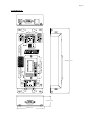
PROTOCOL INTERFACE TRANSLATOR
(PIT)
USER MANUAL
–
Revision 3.13 – 20th August 2001
Page 2
1. INTRODUCTION .....................................................................................................................................................3
2. OPERATION.............................................................................................................................................................3
3. SWITCH SETTINGS.................................................................................................................................................3
3.1.
3.2.
3.3.
3.4.
3.5.
3.6.
ADDRESS SELECTION .............................................................................................................................................4
BAUD RATE SELECTION .........................................................................................................................................4
INPUT PROTOCOL SELECTION ................................................................................................................................4
OUTPUT PROTOCOL SELECTION .............................................................................................................................5
AUTO HOME POSITIONING .....................................................................................................................................5
WRITE PROTECTING HOME POSITION ....................................................................................................................6
4. PTZ MODE DEVICE SPECIFIC OPERATION....................................................................................................6
4.1. DIAGNOSTIC MODE................................................................................................................................................6
4.2. BETATECH / GYYR CONTROLINK ....................................................................................................................6
4.3. VCL ......................................................................................................................................................................6
4.4. MOLYNX ................................................................................................................................................................6
4.5. BAXALL ZTX3 AND ZTX4 ....................................................................................................................................6
4.6. BURLE TC7400 SERIES DOME ..............................................................................................................................6
4.7. PELCO ‘D’ AND ‘P’ ................................................................................................................................................7
4.8. DIAMOND “FAST SCAN” / “SMART SCAN”.............................................................................................................7
4.9. HITACHI CD-08 / MITSUBISHI CCD-300E CAMERAS ............................................................................................8
4.10. JAI CV-S2500 CAMERA .....................................................................................................................................8
4.11. SENSORMATIC RS422 DOME PROTOCOL .............................................................................................................9
4.12. JVC TK-C675 DOME ..........................................................................................................................................9
4.13. DENNARD RS422 DOME PROTOCOL ....................................................................................................................9
4.14. PLETTAC SVD106 / SVD106A .........................................................................................................................10
4.15. GYYR VORTEX...................................................................................................................................................10
4.14.1 Standard Operation......................................................................................................................................10
4.14.2 Tour Define Operation .................................................................................................................................10
4.14.3. Menu Access Operation...............................................................................................................................10
4.16. KOWA DOME .....................................................................................................................................................11
4.17. MIKAMI DOME|..................................................................................................................................................11
4.18. PACOM PROTOCOL .............................................................................................................................................12
4.19. PANASONIC WV-CS600, CS650 .......................................................................................................................12
4.20. VICON ................................................................................................................................................................12
5. DEVICE CONTROL INTERFACE......................................................................................................................13
5.7. ASCII STRING OUTPUT MODE ............................................................................................................................13
6. ALARM CONCENTRATOR.................................................................................................................................13
7. CONNECTIONS .....................................................................................................................................................14
7.1.
7.2.
7.3.
7.4.
7.5.
7.6.
SLAVE PORT CONFIGURED AS RS422 ..................................................................................................................14
SLAVE PORT CONFIGURED AS RS232 ..................................................................................................................14
MASTER PORT CONFIGURED AS RS422 ...............................................................................................................15
MASTER PORT CONFIGURED AS RS232 ...............................................................................................................15
POWER CONNECTION ...........................................................................................................................................15
I2C EXPANSION CONNECTION ..............................................................................................................................15
8. MECHANICAL........................................................................................................................................................16
9. SPECIFICATIONS ..................................................................................................................................................17
LIST OF ABBREVIATIONS
LED
-
Light Emitting Diode
PIT
-
Protocol Interface Translator
PTZ
-
Pan / Tilt / Zoom
Page 3
1. INTRODUCTION
The Betatech Protocol Interface Translator converts Betatech’s BossWare serial command protocol, to various protocols compatible
with equipment from other manufacturers.
The PIT has two serial communications ports. The RS422 / RS485 “Slave” port connects to the BossWare communications loop
and interprets the telemetry control messages. The RS422 / RS485 or RS232 “Master” port connects to the other manufacturer’s
equipment.
The PIT may be configured to operate in various modes:
•
In PTZ mode, the BossWare PTZ control messages are received on the “Slave” communications port. Dependent on the DIP
switch settings, these commands are then translated to serial data packets which are compatible with other manufacturer’s Pan /
Tilt / Zoom telemetry receivers or integrated domes.
•
In device control mode, generic BossWare device control commands are received and translated into data packets compatible
with other manufacturer’s VCR’s, Multiplexers, Quad’s and the like.
•
In Alarm Concentrator mode, alarm inputs and system outputs may be connected via the I2C expansion port on the PIT. This
allows for the connection of up to 256 remote alarms into a system and also for up to 256 system outputs. In device control
mode, the PIT receives generic device control commands from the system main controller.
2. OPERATION
On power up, both the slave channel and the master channel LEDs, will be illuminated.
The PIT unit receives serial messages from the system master controller, via it’s slave communication port. When a valid message
is received, the slave port LED will flash off briefly to indicate message receipt. Only messages addressed to the unit address set up
on DIP switch 2 will be received. Should DIP switch 2 be set to zero (all switches off), then messages addressed to any PTZ unit
will be received by the PIT. The received PTZ control message will then be translated into the appropriate command, compatible
with the PTZ equipment selected by means of DIP switch 3. This message will be transmitted out of the master port to one or more
PTZ telemetry receivers / domes which may be attached to this port. When the message is transmitted, the master port LED will
flash off briefly.
When the PTZ unit does not support addressing (e.g. Mitsubishi RS232 camera), then one PIT is required per PTZ and the various
PTZ units in a system may be individually controlled by setting the address switch on the PIT. When the PTZ unit supports
addressing (e.g. VCL domes), then the PIT may be set to address zero (broadcast) and each PTZ unit on the master communication
port must be set to a unique address. There is no limitation in mixing PTZ units / domes from different manufacturers as long as the
above requirements are met and there is at least one PIT per translation type.
Should an installation require one or more PIT units for protocol translation, this has no effect on the connection / operation of
standard PTZ units, which are compatible with the “native” RS422 protocol generated by the master controller.
Should it be required to use features such as auto-homing, only on specific PTZ units, then these units must be attached to a PIT
which is set up for the required features. Other PTZ units which do not require this feature must be attached to the master port of a
separate PIT, which has this feature disabled. In such a system, each PTZ unit must be at a unique address in order for the master
controller to be able to control it independently.
The PIT takes care of translating fixed speed commands into variable speed commands, which are automatically ramped from slow
to high speed, when the PTZ unit supports variable speed. Similarly, variable speed commands are translated into fixed speed
commands where the PTZ unit does not support variable speed.
The PIT allows for I2C alarm input expansion modules to call preset positions on attached PTZ units. The I2C unit set to address 8,
causes PTZ 1 to move to preset positions 1 to 16 when the corresponding inputs are activated by the closing of an external contact.
I2C expansion unit address 9 operates PTZ 2 etc. I2C expansion unit address 16 operates PTZ 8, allowing for a maximum of 8 PTZ
units to be controlled by the I2C expansion modules in this manner.
3. SWITCH SETTINGS
To access the configuration switches, the two screws on the top cover of the PIT must be removed. The legend on the cover shows
the switches as S1, S2 and S3. Each of these switch groups has 8 individual switches, marked as 1 through 8. Individual switches
are referred to by the switch group, followed by the switch number. e.g. S1/8.
Page 4
3.1. Address Selection
Set switch 2, to the required address of the PIT. This would usually match the camera number in the system. The actual switch
setting is the binary representation of the address. Certain protocols allow for the addressing of multiple devices on the master
communications port (Broadcast mode). In this case, This DIP switch may be set to address zero, which will pass all received
messages through from the slave to the master port. The following table shows the first few addresses:
Address
S2/8
S2/7
S2/6
S2/5
S2/4
S2/3
S2/2
S2/1
Switch
Legend
Address
7
Address
6
Address 5
Address 4
Address 3
Address 2
Address 1
Address 0
0 (B/cast)
off
off
off
off
Off
Off
off
off
1
off
off
off
off
Off
Off
off
on
2
off
off
off
off
Off
Off
on
off
3
off
off
off
off
Off
Off
on
on
4
off
off
off
off
Off
on
off
off
5
off
off
off
off
Off
on
off
on
6
off
off
off
off
Off
on
on
off
on
on
on
on
On
on
on
on
…
255
There is one exception to input protocol. When the input address is set to 255, the PIT will receive 8 bit data and operate in
broadcast mode.
3.2. Baud Rate Selection
Switch 3, positions 7 and 8 are used to set the slave port baud
rate as per the following table:
Baud Rate
S3/8
S3/7
1200 baud
off
off
9600 Baud
off
on
19.2 Kbaud
on
off
57.6 Kbaud
on
on
3.3. Input Protocol Selection
Switch 3, positions 1 to 4 are used to set the protocol which the PIT expects to receive on it’s slave communications port.
Input / Received Protocol Compatible With
S3/4
S3/3
S3/2
S3/1
Reserved
Off
Off
off
off
BossWare (first group)
Off
Off
off
on
BossWare (second group)
Off
Off
On
Off
Reserved
Off
Off
on
off
Device Control Interface
On
On
on
Off
Alarm Concentrator
On
On
on
on
Reserved, binary values 3 to 14
Page 5
3.4.
Output
Selection
Protocol
Switch 1, positions 1 to 4 are
used to set the protocol which
the PIT will transmit on it’s
master
communications
channel.
Note that the group selection
must be carried out as described
under
“Input
Protocol
Selection”.
Output / Transmitted Protocol Compatible
With
Group
S1/4
S1/3
S1/2
S1/1
Text / diagnosis output
First
off
Off
off
off
Betatech / GYYR Vortex
First
off
Off
off
on
VCL Dome (VCLTP)
First
off
Off
on
off
Molynx (Visilynx)
First
off
Off
on
on
Baxall (ZTX3 / ZTX4)
First
off
On
off
off
Burle TC7400 AutoDome
First
off
On
off
on
Pelco Intercept “D” & “P”
First
off
On
on
off
Diamond SmartScan
First
off
On
on
on
Hitachi CD-08 / Mitsubishi CCD-300E Cameras
First
on
Off
off
off
JAI SV-2500
First
on
Off
off
on
Sensormatic RS422
First
on
Off
on
off
JVC TK-C675
First
on
Off
on
on
Ernitec ERNA protocol
First
on
On
off
off
Samsung SPP-12
First
on
On
off
on
Dennard
First
on
On
on
off
Mark Mercer
First
on
On
on
on
Plettac SVD106/SVD106A
Second
off
Off
off
off
Teljoy
Second
off
Off
off
on
AD Biphase
Second
off
Off
on
off
Gyyr Vortex
Second
off
off
on
on
Kowa Dome
Second
off
on
off
off
Mikami Dome
Second
off
on
off
on
Pacom
Second
off
on
on
off
Panasonic CS600 / CS650
Second
off
on
on
on
Vicon
Second
on
off
off
off
3.5. Auto Home Positioning
All PTZ units which support preset positioning, may take advantage of
auto-homing when used in conjunction with the PIT. To use this
feature, switch 1, positions 6 to 7 are used as follows:
Auto Home Time-out
S1/7
S1/6
Auto-homing disabled
off
Off
Should an auto-home time-out value be set, then the PTZ will
automatically be caused to return to preset position 1 after the
expiration of the time-out. The time-out is calculated from the time
the PTZ was last moved.
15 seconds
off
on
1 minute
on
off
3 minutes 45 seconds
on
on
Page 6
3.6. Write Protecting Home Position
The home position may be write protected by switching SW1/8 on. In this mode, it is not possible to modify preset position 1.
4. PTZ MODE DEVICE SPECIFIC OPERATION
4.1. Diagnostic Mode
In this mode of operation, every received PTZ control command is converted into a readable text string. This string is transmitted
out of the PIT master communications port at 9600 baud, no parity, 8 data bits and 1 stop bit.
4.2. Betatech / GYYR CONTROLINK
In this mode of operation, the PIT generates output data which will
control either the Betatech PTZC or the GYYR ControLink RD.
This mode is used to convert from BossWare 9 bit mode, to 8 bit PC
compatible mode, or to change the communication baud rate.
Note that the additional functions such as PTZ home positioning are
NOT implemented in this mode.
Output Baud Rate
S1/6
S1/5
1200 baud
Off
Off
2400 baud
Off
On
9600 baud
On
Off
19.2 Kbaud
On
On
The output data may be in standard BossWare compatibe mode (9
bit data transmission) or 8 bit mode, which is more compatible with PCs
Output Data Format
S1/8
8 Bit PC compatible data
Off
9 Bit BossWare compatible data
On
4.3. VCL
The VCL auxiliaries for this dome have been assigned
the following functions by the PIT:
Keyboard function
VCL Function
Aux 1
Operates the 180 degree turn function
Aux 2
Turns auto focus on
Aux 3
Recalls alarm preset position (high speed)
Aux 4
Saves alarm preset position
4.4. Molynx
When set for Molynx compatible protocol output, switch 1/5 is used to set fixed
speed / variable speed control. When this switch is off, full variable speed
control is allowed. When this switch is on, only fixed speed commands are
transmitted to the Molynx telemetry receiver.
The auxiliary outputs are mapped to the Molynx telemetry receiver as follows:
Keyboard function
Molynx Function
Aux 1
Aux 1
Aux 2
Aux 2
Aux 3
Wash
Aux 4
Wipe
Aux 5
Lamps
Aux 6
Lens slow
Aux 7
Camera
Aux 8
Home
4.5. Baxall ZTX3 and ZTX4
The PIT generates data for this protocol at 1200 baud. Ensure that the telemetry receiver is set for this data rate. The first 8 preset
positions are supported for receivers which support this function.
4.6. Burle TC7400 Series Dome
When in the Burle mode of operation, the output baud rate may be set by
means of DIP switch S1/5
Master (Output) channel Baud Rate
S1/5
9600 Baud
Off
2400 Baud
On
Page 7
4.7. Pelco ‘D’ and ‘P’
In Pelco ‘D” mode of operation, 255 addresses are supported.
Setting DIP 1/8 on selects Pelco ‘P’ mode. In ‘P’ mode, the adjacent
table shows the selection of the valid address range.
4.8. Diamond “Fast Scan” / “Smart Scan”
When in the Diamond mode of operation, only 8 cameras may
be controlled by a single PIT in broadcast mode. Selection of
which group of 8 cameras may be carried out by means of
DIP switch S1.
For any address outside of this range, a dedicated PIT per
Diamond dome would be required.
The auto home timeout for the diamond dome is as per the
following table:
Various additional functions of the Diamond dome are
supported by the operation of the auxiliary outputs:
Address Range
S1/6
S1/5
Address 1 to 32
Off
Off
Address 33 to 64
Off
On
Address 65 to 96
On
Off
Address 97 to 128
On
On
Valid Addresses in Broadcast mode
S1/7
S1/6
S1/5
Address 1 to 8 inclusive
Off
Off
Off
Address 9 to 16 inclusive
Off
Off
On
Address 17 to 24 inclusive
Off
On
Off
Address 25 to 32 inclusive
Off
On
On
Address 33 to 40 inclusive
On
Off
Off
Address 41 to 48 inclusive
On
Off
On
Address 49 to 56 inclusive
On
On
Off
Address 57 to 64 inclusive
On
On
On
Aux Output
Aux Output
Function
1 to 8
Operate dome aux output
9
Invvoke Smartscan Menu
10 to 19
Numeric ‘0’ through ‘9’
20
Enter key
21
Escape key
22
Program Preset, Menu
23
Program Vectorscan, Menu
24
List Preshots
25
Run Vectorscan Once, Menu
26
Continuous Vectorscan, Menu
Function
27
Go to Preshot, Menu
28
Display On / Off
29
Coord Display On / Off
31 TO 40
Continous Vectorscan 1 to 10
41 TO 50
Vectorscan Once 1 to 10
51
Key ‘E’
52
Key ‘C’
53
Key ‘D’
54
Key ‘S’
55
Key ‘N’
Page 8
4.9. Hitachi CD-08 / Mitsubishi CCD-300E Cameras
Full functionality of zoom, focus, iris and preset positioning is supported when used in conjunction with the PIT. Obviously, as the
camera does not incorporate a pan / tilt head, these functions are not available.
4.10. JAI CV-S2500 Camera
This camera does not support preset
positioning and therefore the description in
3.5 and 3.6 is not applicable.
SW1/8 is used to prevent access to the
camera configuration menu from the
standard control keyboard. If this switch is
in the off position, then the menu may be
invoked by storing preset position 1. The
up / down / left and right arrow keys then
allow selection of various menu items. To
leave the menu, store preset position 1
again. This switch being in the on position
also limits the operator’s access to certain
functions as described below.
The
following table lists the keyboard
functions:
Additional functions may be accessed by
recalling preset positions as per the
following table. These functions may also
be accessed by operating the auxiliary
output from the control system. Note that
Aux 1 to 8 operate as described above.
Keyboard
function
Jai Camera Function
Iris [C]
Selects AGC
Iris [O]
Selects manual gain control mode with maximum gain
(255)
Aux 1
Selects AGC
Aux 2
Selects manual gain control mode with gain of 50
Aux 3
Selects manual gain control mode with gain of 100
Aux 4
Selects manual gain control mode with gain of 150
Aux 5 – AutoPan
Selects manual gain control mode with gain of 200
Aux 6 - PTZ F1
Switches off backlight compensation
Aux 7 - PTZ F2
Selects backlight compensation pattern 1
Aux 8 - PTZ F3
Selects backlight compensation pattern 1
Preset
Number
Access
controlled
by S1/8
Aux
Access
Jai Camera Function
1
No
n/a
Manual gain set to 0
2
No
n/a
Manual gain set to 50
3
No
n/a
Manual gain set to 100
4
No
n/a
Manual gain set to 150
5
No
n/a
Manual gain set to 200
6
No
n/a
Manual gain set to 255
7
No
n/a
AGC On
8
No
n/a
AGC fixed gain
Page 9
The following functions are all accessible via auxiliary control commands:
Preset
Number
Access
controlle
d by S1/8
Jai Camera Function
AGC manual gain
24
Yes
One push white balance
No
Backlight compensation off
25
Yes
No
Backlight compensation pattern
1
One push white balance (as per
JAI K/B)
26
Yes
White balance 3200K
27
Yes
White balance 4600K
28
Yes
White balance 5600K
29
Yes
Gamma 0.45
30
Yes
Gamma 0.60
30
Yes
Gamma 1.0
32
Yes
Negative image
33
Yes
Normal (positive) image
34
Yes
Down key
35
Yes
Up key
36
Yes
Left key
37
Yes
Right key
38
Yes
Menu toggle
Preset
Number
Access
controlle
d by S1/8
9
No
10
11
Jai Camera Function
12
No
Backlight compensation pattern
2
13
Yes
Auto shutter on
14
Yes
Flickerless shutter
15
Yes
Auto shutter off
16
Yes
Shutter speed 1/250
17
Yes
Shutter speed 1/500
18
Yes
Shutter speed 1/1000
19
Yes
Shutter speed 1/2000
20
Yes
Shutter speed 1/4000
21
Yes
Shutter speed 1/10000
22
Yes
Auto white balance
23
Yes
Manual white balance
4.11. Sensormatic RS422 Dome Protocol
Only 7 preset positions are currently supported by the PIT.
4.12. JVC TK-C675 Dome
When in the JVC mode of operation, only 99 cameras may be controlled by
a single PIT in broadcast mode. Selection of which group of 99 cameras
may be carried out by means of DIP switch S1/5
Note that as the dome address range is limited to 99, the PIT set to control
domes in the range 101 to 199 modifies the address by subtracting 100. To
control a JVC dome address 101, the dome must be set to address 1 and
connected to the PIT with S1/5 ON.
The generated protocol may be optimised for the standard JVC protocol, or
the extended model ‘B’ protocol, which allows for a greater range of
variable speeds.
Valid Addresses in Broadcast mode
S1/5
Address 1 to 99 inclusive
Off
Address 101 to 199 inclusive
On
JVK Model
S1/6
TK-C675B
Off
TK-C675
On
Turn on DIP S1/7 to enable auto-focus.
4.13. Dennard RS422 Dome Protocol
The Dennard dome allows for the display of configuration menus. This
feature may optionally be disabled using S1/5.
The menu may be accessed by using Aux 6 (Shown as PTZ F1 on the PCK).
The accept function for this dome is “Recall preset position 1”. A shortcut to
accept is via Aux 8 (Shown as PTZ F3 on the PCK).
Menu Access
S1/5
Access available
Off
Access prohibited
On
Page 10
4.14. Plettac SVD106 / SVD106A
The Plettac dome allows for the display of configuration menus. This feature
may optionally be disabled using S1/8.
Menu Access
S1/8
Access available
On
Access prohibited
Off
4.15. Gyyr Vortex
Output Baud Rate
S1/6
S1/5
In this mode of operation, the PIT generates output data that will
control the GYYR VORTEX DOME , set to the “Gyyr” protocol.
Note that this is different to the GYYR Controlink protocol.
Baud rates are set as per the following table.
1200 baud
Off
Off
2400 baud
Off
On
9600 baud
On
Off
Note that the additional functions such as PTZ home positioning are
NOT implemented in this mode.
19.2 Kbaud
On
On
Menu Function
S1/8
S1/7
Standard
Off
Off
Tour Define
Off
On
Menu Access
On
Off
Reserved
On
On
The auxiliaries are mapped differently depending on the settings of
S1/7 and S1/8.
4.14.1 Standard Operation
In this mode auxiliary 1 to 8 operate the standard auxiliary functions of the
Vortex dome. Certain auxiliaries are mapped to special functions as per the
following table:
Standard Mode Aux Function
Aux
Tour 1
9*
Note *: Set aux to 1 (on) to run tour. Set to 2 to end tour define. Set to 3 to start
tour define.
Tour 2
10 *
Note **: Set the aux to the value of the keystroke which is required.
Tour 3
11 *
Menu Access
4.14.2 Tour Define Operation
Aux 1: start tour 1 define
Aux 2: end tour 1 define
Aux 3: start tour 2 define
Aux 4: end tour 2 define
Aux 5: start tour 3 define
Aux 6: end tour 3 define
Aux 7: start tour 1
Aux 8: end tour 2
4.14.3. Menu Access Operation
Aux 1: Menu access
Aux 2: Menu key up
Aux 3: Menu key stop
Aux 4: Menu key down
Aux 5: Menu key left
Aux 6: Menu key right
Aux 7: Menu key cancel
Aux 8: Menu key enter
Menu keystroke
12
13 **
Page 11
4.16. Kowa Dome
Auxiliaries on the Kowa dome are mapped as per the following table:
Kowa Dome Aux Function
If SW1/5 is on, then the PIT will generate 9 different speed settings, compatible
with older Kowa domes. When this switch is on, then the PIT will generate 14
different speed settings, compatible with newer domes.
Menu Access
1
Menu key up
3
Menu key down
4
Menu key left
5
Menu key right
6
Set Autopan Start
9
Set Autopan End
10
Start Autopan
11
Home position
12
Remote reset
13
Autoflip on / off
14
4.17. Mikami Dome|
PIT RS422
Master port
Please note that the RS422 connection on this dome does not adhere to the standard. Connect
as per the following table:
The auxiliaries are mapped as per the following table
Mikami Dome Aux Function
Aux
Camera Manual
1
Camera Auto
2
EC 0
3
EC 1
4
Autopan (preset 63 to 64)
5
Stop Autopan
6
Auto EC
8
Set shutter speed
9
Set Gain
10
Set white balance
11
Aux Value
Autopan speed
0
1
2
3
0
1
2
3
0
1
2
3
:
:
:
:
:
:
:
:
:
:
:
:
1/60 s
1/100 s
1/500 s
1/1000 s
0 dB
+6 dB
+12 dB
+18 dB
Auto
Indoor
Outdoor
One push trigger
Aux
Mikami
Dome
TX[+]
B
TX[-]
A
GND
GND
Page 12
4.18. Pacom Protocol
Address Range
S1/6
S1/5
Output Baud Rate
S1/8
S1/7
Address 1 to 16
Off
Off
4800 baud
Off
Off
Address 17 to 32
Off
On
1200 baud
Off
On
Address 33 to 48
On
Off
2400 baud
On
Off
Address 49 to 64
On
On
900 baud
On
On
Note that the address sent to the Pacom receiver always falls into the address range 0 to 15, which is set on the receiver. The above
table specifies which range of addresses will be accepted by the PIT and mapped into the address range of the receiver.
4.19. Panasonic WV-CS600, CS650
This dome supports an address range from 1 to 96 only.
Please note that although the protocol is compliant with that provided by Panasonic, there is an issue with Preset position storage. It
may be necessary to store a preset position more than once for it to be functional. On the first attempt, the dome will sometimes
carry out a preset restore operation.
The function of the 8 aux keys are dependent on the setting of DIP S1/8.
Aux #
Function
S1/8
Aux #
Function
S1/8
1
Preset Sequence Off
Off
1
Menu On
On
2
Preset sequence on
Off
2
Menu Off
On
3
Autopan Off
Off
3
Menu Up
On
4
Autopan On
Off
4
Menu Down
On
5
One push focus
Off
5
Menu Left
On
6
N/a
Off
6
Menu Right
On
7
N/a
Off
7
Menu Esc
On
8
N/a
Off
8
Menu Enter
On
4.20.
Vicon
The PIT generates data at 4800 baud. Set S1/8 for duplex if the Vicon telemetry is set for Duplex. The return data is not actually
used and this setting affects the timing of the commands only. It is preferable to use simplex mode
on the PIT and Vicon receivers / domes.
Output Protocol
S1/8
Certain auxiliaries are mapped as per the functions in the following table.
Simplex
Off
To access the menu of the Vicon Surveyor 99 dome, store preset number 94. The arrow keys,
joystick, autopan (aux 5) and auto-iris (aux 7) keys may be used to navigate the menus.
Duplex
On
Aux #
Function
5
Autopan
7
Auto Iris
8
Lens Speed
Page 13
5. DEVICE CONTROL INTERFACE
In this mode of operation, DIP switches 2 and 3 must be set up as shown in sections 3.1. through 3.3. DIP switch 1 is used to select
the output protocol which is used to control the external device as per the following table:
Output / Transmitted Protocol Compatible With
S1/4
S1/3
S1/2
S1/1
Text / diagnosis output
off
Off
Off
off
ASCII string mode
On
On
On
On
Note that device operation may be achieved either by means of a serial message from a system controller, or from I2C keyboard(/s)
connected to the I2C expansion port of the PIT. The I2C expansion keyboard at address 3 maps to functions F1 to F16 and that at
address 4 maps to functions F17 to F32.
5.7. ASCII String Output Mode
In this mode of operation, the actual text string which is to be
sent to the device via the master channel is received on the
slave channel. Sixteen functions have been defined (0x20 to
0x3f). DIP switch 1 positions 5 to 8, determine which function
is received. The PIT will only respond to one of these
functions, dependant on the settings of DIP 1.
The master port baud rate for ASCII string mode is set up by
S3/6 and S3/5 as per the following table.
Valid Function Number
S1/8
S1/7
S1/6
S1/5
0x20
Off
Off
Off
Off
0x21
Off
Off
Off
On
0x22
Off
Off
On
Off
0x23
Off
Off
On
On
0x24
Off
On
Off
Off
Master Port Baud Rate
S3/6
S3/5
0x25
Off
On
Off
On
1200 baud
Off
off
0x26
Off
On
On
Off
2400 baud
Off
on
0x27
Off
On
On
On
9600 Kbaud
On
off
…
19.2 Kbaud
On
on
0x2f
On
On
On
On
6. ALARM CONCENTRATOR
Master Port Serial Mode
S1/2
S1/1
In this mode of operation, DIP switches 2 and 3 must be set up as
shown in sections 3.1. through 3.3.
No Message Transmitted
Off
Off
ASCII / Text message transmitted
Off
On
BossWare Alarm message Transmitted
On
Off
Master Port Baud Rate
S1/4
S1/3
1200 baud
Off
off
9600 baud
Off
on
19.2 Kbaud
On
off
57.6 Kbaud
On
on
In ASCII / Text mode, all changes in the input state are transmitted
out of the master communications port in ACSII at 8 data bits, no
parity, 1 stop bit. Also all I2C expansion inputs are copied to the
I2C expansion outputs.
In BossWare mode all alarm input information is transmitted out of
the master port in BossWare format. This allows for another alarm
concentrator to be connected via RS422 and it’s (remote) outputs to
mirror the (local) alarm input status. In this mode 2 PIT units may
be connected “back to back”, via RS422, with each PIT I2C outputs
reflecting the other PIT I2C inputs.
Page 14
7. CONNECTIONS
7.1. Slave Port Configured as RS422
Control messages from the master control device, which generates the PTZ control information, are received on this port. The
RS422 configuration allows for multiple PITs to be connected on a common communications line. Connections are as follows:
Pin Number
Pin Function
1
RS422 Receive data [-] (from BossWare master RS422 Tx[-])
2
RS422 Receive data [+] (from BossWare master RS422 Tx[+])
3
RS422 Transmit data [+] (to BossWare master RS422 Rx[+])
4
RS422 Transmit data [-] (to BossWare master RS422 Rx[-])
5
RS422 Communications common
6
n/c
7
n/c
8
n/c
9
n/c
Should it be required to operate the PIT in RS485 mode, then the TX pair and the RX pair must be joined together on this connector.
i.e. Pin 1 to pin 4 and pin 2 to pin 3.
7.2. Slave Port Configured as RS232
Pin Number
Pin Function
1
Internally connected to pins 4 and 6
2
TXD (data to master / control device RXD)
3
RXD (data from master / control device TXD)
4
Internally connected to pins 1 and 6
5
GND
6
Internally connected to pins 4 and 6
7
CTS (from master / control device RTS)
8
RTS (to master / control device CTS)
9
n/c
Page 15
7.3. Master Port Configured as RS422
Translated control messages, generated by the PIT, are transmitted on this port. The RS422 configuration allows for multiple PTZ
receivers to be connected on a common communications line, should the PTZ receivers support unit addressing. Connections are as
follows:
Pin Number
Pin Function
1
RS422 Transmit data [-] (to slave device RS422 Rx[-])
2
RS422 Transmit data [+] (to slave device RS422 Rx[+])
3
RS422 Receive data [+] (from slave device RS422 Tx[+])
4
RS422 Receive data [-] (from slave device RS422 Tx[-])
5
RS422 Communications common (from slave device communications common)
6
n/c
7
n/c
8
n/c
9
n/c
7.4. Master Port Configured as RS232
Pin Number
Pin Function
1
Internally connected to pins 4 and 6
2
TXD (data to slave device RXD)
3
RXD (data from slave device TXD)
4
Internally connected to pins 1 and 6
5
GND
6
Internally connected to pins 4 and 6
7
CTS (from slave device RTS)
8
RTS (to slave device CTS)
9
n/c
7.5. Power Connection
The unit is be powered by 7 to 25 VAC 50/60 Hz or 8 to 34VDC @ 1.5W. This is applied via the external power connector.
7.6. I2C Expansion Connection
Pin Number
Pin Function
1
VCC (+ 5VDC out to external I2C device)
2
SDA (I2C data)
3
SCL (I2C clock)
4
GND (Common)
4
5
6
7
8
1
2
3
4
5
6
7
8
74.00m m [2.91"]
8
7
6
5
4
3
2
1
R E M O V E S C R E W S TO C H A N G E
E P R O M / D IP S W IT C H E S
3
S E T /C H E C K E P R O M
A N D D IP S W IT C H
S E T T IN G S F O R
P IT F U N C T IO N A L I T Y
2
S1
1
T O F IE L D /
C O N T R O L L E D D E V IC E
TO M A S TER /
C O N T R O L L IN G D E V IC E
Page 16
8. MECHANICAL
190.90m m [7.52"]
M ASTER CHANNEL
31.20m m [1.23"]
Page 17
9. SPECIFICATIONS
Compliance
Power Requirements
Mechanical
Environmental
Slave Communications
Port
Master Communications
Port
Connector Type
PTZ Translation Options:
NOTE: The transmitted data
may be set to control certain
functions of equipment from the
listed manufacturers.
No
representation is made that the
generated data conforms in every
respect to that of the listed
equipment manufacturer.
Functions
Other
Device Control Options:
Device Control functions:
EN55022 for radiated and conducted emissions
IEC 801-3, Class 3 for RF susceptibility
7 to 25 VAC 50/60 Hz or 8 to 34VDC @ 1.5W, requires external power adapter
Dimensions: 74mm (W) X 31.2 mm (H) X 190.9mm (D)
Weight: 390g
Finish: Brushed stainless steel
Operating Temperature: -10 to +50 deg C
Storage Temperature: -20 to +65 deg C
Humidity: 0 to 95% RH (non-condensing)
Baud Rate: 9600 Baud, 19.2 KBaud, 57.6 Kbaud or 115.2 Kbaud
Addressing range: Broadcast or 1 to 255
Protocol: BossWare.
Electrical: RS422, can be wired for RS485.
Baud Rate: From 1200 Baud to 57.6 Kbaud, dependent on required translation type.
Electrical: RS422, can be wired for RS485. Optionally RS232.
RS232 D9 Male
RS422 D9 Female
Power 2.0mm DC plug
I2C 6 position RJ45 (4 fitted)
Diagnostic / text output
VCL VCLTP protocol dome
Molynx (Visylinx)
Baxall ZTX3 and ZTX4
Burle TC7400 series dome (9600 or 2400 baud)
Pelco Intercept “D” or “P” protocol
Diamond SmartScan (Address 1 to 8, 9 to 16 or single address)
Mitsubishi CCD-300E camera
Computar CD-08 camera
Sensormatic UltraDome (RS422 dome protocol)
JVC TK-C675A or B Dome (Address 1 to 99 or 101 to 199)
Ernitec ERNA Protocol
Samsung SPP12 RS422 Protocol
Dennard RS422 Protocol
Mark Mercer RS422 Protocol
Plettac SVD106 / SVD106A Dome Protocol
American Dynamics Bi-Phase Protocol (Can control only 1 PTZ at a time)
Teljoy / Provicom RS422 Protocol
Gyyr Vortex
Kowa Dome
Mikami Dome
Pacom 2005, 2017, 2018
Panasonic WV-CS600,CS650,CS850
Vicon RS422 telemetry receiver / Surveyor 99 dome
Pan, tilt, zoom, focus, iris, 64 position presets store and recall, auxiliary function control.
Functions not available on selected translation target device are excluded.
Switch selectable write protection of preset home position
Auto homing selectable, off, 15 sec, 1 min or 3 min 45 Sec.
Diagnostic / text output
Configurable ASCII text strings (when used in conjunction with VideoBloX matrix)
Either via serial commands or device at address 1 may have certain functions controlled via
I2C expansion keyboards.