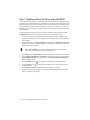
1
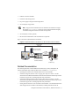
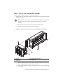
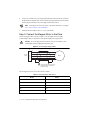
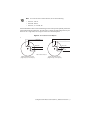
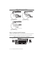
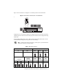
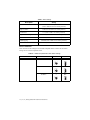
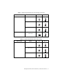
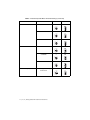
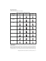
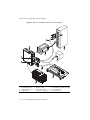
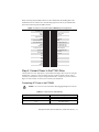
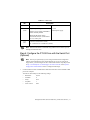
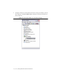
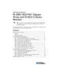
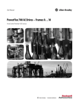
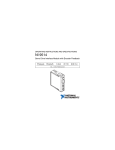
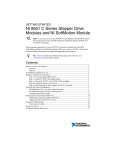
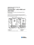
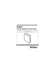
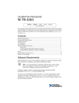
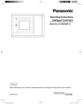
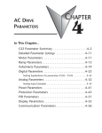
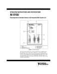
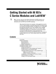
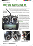
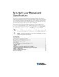
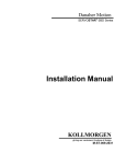
GETTING STARTED NI 9512 C Series Modules and P7000 Series Stepper Drives Note If you are a new user of LabVIEW or are unfamiliar with LabVIEW, refer to the Getting Started with LabVIEW manual for information about LabVIEW and LabVIEW terminology. This manual helps you quickly install and configure the P7000 series stepper drives and stepper motors. If you encounter any problems during setup, refer to the Tips and Troubleshooting section for assistance. Tip Contents What You Need to Get Started ................................................................................................. 2 Software............................................................................................................................ 2 Hardware .......................................................................................................................... 2 Related Documentation .................................................................................................... 3 Hardware Installation and Configuration ................................................................................. 4 Step 1: Set Up the CompactRIO System .......................................................................... 5 Step 2: Connect the Stepper Motor to the Drive .............................................................. 6 Step 3: Configure the DIP Switches ................................................................................. 8 Step 4: Connect the NI 9512 to the P7000 Drive ............................................................. 17 Step 5: Connect Power to the P7000 Drive ...................................................................... 19 Step 6: Configure the P7000 Drive with the Serial Port (Optional) ................................. 21 Software Configuration and Installation................................................................................... 23 Step 1: Install the P7000 Tools (Optional) ....................................................................... 23 Step 2: Test the Motor With the P7000 Tools (Optional) ................................................ 27 Step 3: Install Software on and Configure the NI RT Controller ..................................... 28 Step 4: Create a Project in Scan Interface Mode .............................................................. 29 Step 5: Add Resources to the Project ............................................................................... 30 Step 6: Configure the NI 9512 Axis ................................................................................. 31 Step 7: Enable and Test the Drive using LabVIEW......................................................... 34 Tips and Troubleshooting ......................................................................................................... 35 Status LED on the Drive is Off, Blinks, or is Red............................................................ 35 P7000 Tools Jog Toolbar Does Not Move The Motor ..................................................... 35 The Motor Gets Hot When Idle........................................................................................ 35 The Motor Moves Backwards .......................................................................................... 35 The P7000 Software Does Not Detect the Drive.............................................................. 35 Worldwide Support and Services ............................................................................................. 36 What You Need to Get Started You need the following items to get started. Software LabVIEW 2009 or later LabVIEW 2009 Real-Time Module or later NI-RIO 3.2.0 or later LabVIEW 2009 NI SoftMotion Module or later P7000 Tools configuration software (optional) Note The RS-232 serial configuration cable and P7000 Tools configuration software are required only if you are using a third-party motor. If you are using an NI stepper motor, you can perform configuration using only the DIP switches on the drive. Hardware NI 9512 C Series drive interface module NI 9512-to-P7000 stepper drives connectivity bundle. This product contains the following items: – A cable to directly connect the NI 9512 DSUB with the P7000 series stepper drive – A 37-pin terminal block and cable for connecting the NI 9512 MDR connector to other I/O NI real-time controller – CompactRIO controller and chassis that support the RIO Scan Interface Tip To determine if your controller and chassis support the RIO Scan Interface go to ni.com/info and enter the Info Code rdsoftwareversion. or – NI 9144 distributed chassis and compatible RT controller Power supply for the controller Refer to the hardware specifications for information about selecting an appropriate power supply. Note A separate power supply for the modules 2 | ni.com | Getting Started with NI 9512 and P7000 Drives Ethernet connection and cable P70360 or P70530 stepper drive DC power supply if using the P70530 stepper drive NI or third-party stepper motor Note Stepper motors available from NI are matched to the P7000 series stepper drive. Refer to ni.com/motion for motor options. National Instruments highly recommends using these motors for the best user experience. NI or third-party encoder (optional) RS-232 serial communication cable for P7000 drives (optional) Figure 1 shows the required hardware and software. Figure 1. Required Hardware and Software for NI 9512 Drive Interface Module RS-232 Cable (Optional) +24 V Power Supply (NI PS-15 Shown) P7000 Direct Connect Cable Ethernet Cable NI RT Controller (NI cRIO-9014 shown) and NI 9512 Module P7000 Series Stepper Drive (P70360 shown) NI Stepper Motors DC Power Supply (P70530 only) Related Documentation The following documents contain additional information that you may find helpful. All referenced documents ship with the product and are available at ni.com/manuals. • Operating instructions for the controller and NI 9512 C Series module. • P70360 (AC) High Performance Micro-stepping Drive Reference Guide—Use this document to learn additional information about the electrical and mechanical aspects of the P70360 AC stepper drive, including important safety information. • P70530 (DC) High Performance Micro-stepping Drive Reference Guide—Use this document to learn additional information about the electrical and mechanical aspects of the P70530 DC stepper drive, including important safety information. • Getting Started with NI 951x C Series Modules and LabVIEW—Use this document to learn about using the NI 951x modules with LabVIEW, including information about the Getting Started with NI 9512 and P7000 Drives | © National Instruments | 3 LabVIEW NI SoftMotion Module and how to set up a system using the NI 9144 distributed chassis. To access this document, select Start»All Programs»National Instruments» LabVIEW»LabVIEW Manuals»Getting_Started_NI_951x_Modules_LabVIEW.pdf. • LabVIEW NI SoftMotion Module Help—Use this help file to learn about using the NI SoftMotion Module in LabVIEW including information about function blocks and using the NI SoftMotion Module with the LabVIEW Project. To access this help file from LabVIEW, select Help»LabVIEW Help, then expand the LabVIEW NI SoftMotion Module book on the Contents tab. • NI 9144 User Guide and Specifications—Use this document to learn additional information about how to connect the NI 9144 chassis to a network, how to use the NI 9144 chassis features, and contains the NI 9144 chassis specifications. • NI Industrial Communications for EtherCAT software documentation. • LabVIEW Help—Use the LabVIEW Help to access information about LabVIEW programming concepts, step-by-step instructions for using LabVIEW, and reference information about LabVIEW VIs, functions, palettes, menus, tools, properties, methods, events, dialog boxes, and so on. The LabVIEW Help also lists the LabVIEW documentation resources available from National Instruments. Access the LabVIEW Help by selecting Help»LabVIEW Help. • Getting Started with LabVIEW—Use this document as a tutorial to familiarize yourself with the LabVIEW graphical programming environment and the basic LabVIEW features you use to build data acquisition and instrument control applications. Access the Getting Started with LabVIEW PDF by selecting Start»All Programs»National Instruments» LabVIEW»LabVIEW Manuals»LV_Getting_Started.pdf. Hardware Installation and Configuration You can configure the P7000 series stepper drives using the external DIP switches or with software through the RS-232 port. If you have an NI stepper motor, you can configure the drive and motor using only the DIP switches. If you have a third-party motor, you must use the P7000 Tools configuration software. Note This document assumes you have already installed your NI 9512 C Series module and all required software to the host computer. Refer to the Getting Started with NI 951x C Series Modules and LabVIEW, available from ni.com\manuals and installed with the NI LabVIEW NI SoftMotion Module, for installation information. Software installation onto the RT target is covered in Step 3: Install Software on and Configure the NI RT Controller. 4 | ni.com | Getting Started with NI 9512 and P7000 Drives Step 1: Set Up the CompactRIO System Complete the following steps to set up the CompactRIO hardware. 1. Install the real-time CompactRIO controller on the chassis if you are not using an integrated controller and chassis. Note Write down the controller serial number before installing the controller onto the chassis. You will be unable to read the serial number after you install the controller. a. Make sure that no power is connected to the controller or the chassis. b. Align the controller with the chassis as shown in Figure 2. Figure 2. Installing the Controller on the Chassis (Eight-Slot Chassis Shown) 5 1 4 3 2 1 2 3 Controller Captive Screws Controller Slot 4 5 Reconfigurable Embedded Chassis Grounding Screw c. Slide the controller onto the controller slot on the chassis. Press firmly to ensure the chassis connector and the controller connector are mated. d. Using a number 2 Phillips screwdriver, tighten the two captive screws on the front of the controller. Getting Started with NI 9512 and P7000 Drives | © National Instruments | 5 2. Connect the controller to a power supply and an Ethernet network on the same subnet as the development computer. Refer to the controller operating instructions for information about wiring the controller to the power supply and Ethernet network. Do not plug in or turn on any power to the system until after you complete Step 5: Connect Power to the P7000 Drive. Note 3. Install the NI 9512 module in slot 1, 2, 3, or 4 of the chassis. Step 2: Connect the Stepper Motor to the Drive Connect the stepper motor as shown in Figure 3. The NI stepper motors are highly recommended, as they are optimized to work with the P7000 series stepper drives. Do not hot-plug the motor connector. Also, avoid “whiskers” from stranded phase leads protruding from the motor plug. Caution Figure 3. Connecting the Stepper Motor J6 1 2 Motor Power 3 4 5 A– A+ B– Motor B+ Earth GND To avoid electrical shock, motor ground must be connected to protective earth. The NI stepper motor wire color code is shown in Table 1. Table 1. NI Stepper Motor Wire Colors Phase Color A– Orange A+ Black B– Yellow B+ Red PE Green/Yellow Stripe 6 | ni.com | Getting Started with NI 9512 and P7000 Drives Note To reverse the motor rotation direction, do one of the following: • Switch A– with A+ • Switch B– with B+ • Switch A–, A+ with B–, B+ National Instruments offers several standard stepper motors that provide optimum performance when matched with the P7000 drive. The motors have a four flying lead configuration. If your motor has six or eight leads, refer to Figures 4 and 5 for connection options. Figure 4. Six Lead Connection Options Phase A+ Phase A– Phase A+ NC* NC* Phase B+ Phase A– Phase B+ Phase B– NC* NC* Phase B– *NC = Not Connected 6-Wire Half-Coil Connection (Higher Speed, Lower Torque) 6-Wire Series Connection (Higher Torque, Lower Speed) Getting Started with NI 9512 and P7000 Drives | © National Instruments | 7 Figure 5. Eight Lead Connection Options Phase A+ Phase A– Phase A+ Phase A– Phase B+ Phase B+ Phase B– Phase B– 8-Wire Series Connection (Higher Torque, Lower Speed) 8-Wire Parallel Connection (Higher Speed, Lower Torque) Phase A+ Phase A– NC NC Phase B+ Phase B– NC NC *NC = Not Connected 8-Wire Half-Coil Connection (Higher Speed, Lower Torque) Step 3: Configure the DIP Switches Configure the DIP switches as follows for proper operation of your P7000 series stepper drive. Figure 6 shows switches S2–1 through S2–12 in the OFF position for the P70360 drive. OFF 8 9A E 345 67 F01 2 Figure 6. DIP Switches in OFF Position for P70360 Drive 1 2 3 4 5 6 7 8 9 10 11 12 BC D 12 S1 1 S2 8 | ni.com | Getting Started with NI 9512 and P7000 Drives 12 Figure 7 shows switches S2–1 through S2–12 in the OFF position for the P70530 drive. Figure 7. DIP Switches in OFF Position for P70530 Drive OFF ON 8 9A E 345 67 F01 2 1 1 2 3 4 5 6 7 8 9 1011 12 BC D S1 Motor S2 2 Step 4 5 Load 7 8 9 Smooth Computer Setup S1=0, S2 1-12 = OFF High = OFF, Open Low = ON, Closed 10-12Advanced Using Table 4 or 5, set switches S1 and S2-1 to configure the drive for your motor. If you have a third-party motor set the switches for a third-party motor and use the serial configuration using P7000 Tools. For the remaining DIP switches, refer to Table 2 for the switch settings and to Table 3 for the recommended drive settings that correspond to the switch settings. Note For DIP switch settings to take effect, you must power cycle the P7000 series stepper drive whenever you make changes. Table 2. DIP Switch Positions Motor Selection Step Resolution S1 S2–1 S2–2 S2–3 S2–4 Motor Dependent Motor Dependent ON OFF ON O F F O N Dynamic Smoothing Load Inertia O N 2 3 4 Current Reduction Multistepping Encoderless Stall Detection S2–5 S2–6 S2–7 S2–8 S2–9 S2–10 S2–11 S2–12 OFF OFF OFF OFF OFF OFF OFF OFF O F F O F F O F F O F F O F F O F F O F F O F F 5 6 7 8 9 10 11 12 Getting Started with NI 9512 and P7000 Drives | © National Instruments | 9 Table 3. Drive Settings Drive Option Setting Motor selection Motor dependent (refer to Tables 4 and 5 for switch positions) Step resolution 5,000 (refer to Table 6 for switch positions) Load inertia 0–1 (refer to Table 7 for switch positions) Dynamic smoothing Minimal (refer to Table 8 for switch positions) Current reduction Enabled (refer to Table 9 for switch positions) Multistepping Disabled (refer to Table 10 for switch positions) Encoderless stall detection Disabled (refer to Table 11 for switch positions) Motor Selection Table 4 lists the switch settings for AC P70360-compatible motors. Table 5 lists the switch settings for DC P70530-compatible motors. Table 4. P70360-Compatible Motor DIP Switch Settings Motor NI NEMA 23 T21NRLC S1 S2–1 1 OFF 34 5 6 E 7 8 9A F01 2 Motor Frame BC D 2 E 7 8 9A BC D 3 E 7 8 9A BC D 10 | ni.com | Getting Started with NI 9512 and P7000 Drives O F F 1 OFF 34 5 6 F01 2 T23NRLC 1 OFF 34 5 6 F01 2 T22NRLC O F F O F F 1 Table 4. P70360-Compatible Motor DIP Switch Settings (Continued) Motor NI NEMA 34 N31HRLG S1 S2–1 4 OFF 34 5 6 E 7 8 9A F01 2 Motor Frame BC D 5 E 7 8 9A BC D 6 E 7 8 9A BC D 0 7 8 9A F01 2 1 O F F 1 OFF 34 5 6 Serial configuration using P7000 Tools E Third-party O F F OFF 34 5 6 F01 2 N33HRLG 1 OFF 34 5 6 F01 2 N32HRLG O F F O F F 1 BC D Table 5. P70530-Compatible Motor DIP Switch Settings Motor NI NEMA 17 CTP 10 ELF 10 S1 S2–1 D ON 34 5 6 E 7 8 9A F01 2 Motor Frame BC D E ON 34 5 E 7 8 9A BC D CTP 12 ELF 10 F O N 1 ON 34 5 7 8 9A E 6 F01 2 1 6 F01 2 CTP 11 ELF 11 O N O N 1 BC D Getting Started with NI 9512 and P7000 Drives | © National Instruments | 11 Table 5. P70530-Compatible Motor DIP Switch Settings (Continued) Motor NI NEMA 23 T21NRLH S1 S2–1 2 OFF 34 5 6 E 7 8 9A F01 2 Motor Frame BC D 3 E 7 8 9A BC D 4 E 7 8 9A BC D N31HRHJ 1 ON E 7 8 9A BC D E BC D 3 O N 1 ON 34 5 6 E 7 8 9A F01 2 1 ON 7 8 9A F01 2 2 O N 6 BC D 0 F01 2 7 8 9A E O N 1 OFF 34 5 6 BC D 12 | ni.com | Getting Started with NI 9512 and P7000 Drives 1 34 5 N33HRHJ Serial configuration using P7000 Tools O F F 34 5 N32HRHJ Third-party 1 6 F01 2 NI NEMA 34 O F F OFF 34 5 6 F01 2 T23NRLH 1 OFF 34 5 6 F01 2 T22NRLG O F F O F F 1 Step Resolution Table 6 lists the step resolution switch settings. Table 6. Step Resolution DIP Switch Settings Resolution S2–2 S2–3 S2–4 200 (Full Step) ON ON ON O N O N O N 400 (Half Step) 2 OFF 4 ON ON O N O N O F F 2 5,000 3 ON 3 OFF 4 ON O F F O N 10,000 2 3 OFF OFF O F F 18,000 O N 4 ON O F F 2 3 ON ON O N O N O N 4 OFF O F F 25,000 2 OFF O F F 25,400 3 4 OFF OFF O F F O F F 2 3 4 OFF ON OFF O F F O F F 2 50,000 ON O N 3 4 OFF OFF O F F O N 2 O F F 3 4 Load Inertia The P7000 series stepper drives eliminate the resonance typical of step motors with high-speed, digital processing of motor electrical activity. To use this feature, you must set three switches based on the load-to-rotor inertia ratio. These switches select the gain parameter the drive uses to stabilize the motor. You can calculate the load inertia by hand or by using the Motioneering Getting Started with NI 9512 and P7000 Drives | © National Instruments | 13 sizing software. If you do not know your inertia ratio, set the DIP switches to OFF for a load-to-rotor inertia ratio of 0–1. Table 7 lists the load inertia switch settings. Table 7. Load Inertia DIP Switch Settings Load-to-Rotor Inertia Ratio S2–5 S2–6 S2–7 0–1 OFF OFF OFF O F F 1–1.5 O F F O F F 5 6 7 ON OFF OFF O F F O N 1.5–2.5 O F F 5 6 7 OFF ON OFF O F F O F F 5 2.5–5.0 O N 6 7 ON ON OFF O N O N O F F 5.0–7.0 5 OFF O F F 7.0–12.0 6 7 OFF ON O F F 5 6 ON OFF O N 7 ON O F F O N 12.0–20.0 O N 5 6 7 OFF ON ON O N O N O F F 5 20.0–32.0 6 7 ON ON ON O N O N O N 5 14 | ni.com | Getting Started with NI 9512 and P7000 Drives 6 7 Dynamic Smoothing Dynamic smoothing is a temporal filter (second-order, low-pass) applied to the command sequence to reduce jerk. It helps reduce overshoot and lessens the excitation of mechanical resonance in the system. It filters from slightly below the resonant frequency up to well above resonance to remove spectral content that would be misrepresented in the motor output and may also excite other parts of the machine. Dynamic smoothing is a very powerful feature for achieving maximum torque from the motor. However, it is difficult to optimize and is not necessary for the vast majority of applications. Therefore, National Instruments recommends setting both DIP switches to OFF for minimal smoothing. Table 8 lists the dynamic smoothing switch settings. Table 8. Dynamic Smoothing DIP Switch Settings Dynamic Smoothing S2–8 S2–9 Minimal OFF OFF O F F Moderate O F F 8 9 ON OFF O F F O N Heavy 8 9 OFF ON O F F 8 Aggressive O N 9 ON ON O N O N 8 9 Getting Started with NI 9512 and P7000 Drives | © National Instruments | 15 Current Reduction Current reduction reduces drive and motor heating by invoking standby current reduction. When enabled, current reduction cuts motor current to 75 percent of its commanded value 100 ms after receipt of the last step pulse. You can adjust the reduction proportion and delay to other values using the P7000 Tools configuration software. When current reduction is enabled, the motor holding torque is reduced. Do not enable it for applications that require full holding torque when the motor is stationary. Table 9 lists the current reduction DIP switch settings. Note Current reduction is enabled when switch S2–10 is OFF. Table 9. Current Reduction DIP Switch Settings Current Reduction S2–10 Enabled OFF O F F 10 Disabled ON O N 10 Multistepping Multistepping is similar to dynamic smoothing, except it is a much more aggressive use of the filter. Typically, it results in a filter that begins to roll off two octaves below the resonant frequency. This is intended for use with coarse resolution (full/half-step input pulses) to smooth large steps into a continuous train of microsteps, and may provide smoother motion depending on your motion application. Disable multistepping if you are not using full or half step resolution. Table 10 lists the multistepping switch settings. Table 10. Multistepping DIP Switch Settings Multistepping S2–11 Enabled ON O N Disabled 11 OFF O F F 11 16 | ni.com | Getting Started with NI 9512 and P7000 Drives Encoderless Stall Detection The P7000 series stepper drive is uniquely designed to sense the motor shaft position at all times. The drive monitors the commanded position and compares it to the actual position. As with any two-phase step motor, when the shaft position and commanded position are greater than two full steps apart, a stall is detected, and the drive faults. Table 11 lists the encoderless stall detection switch settings. Table 11. Encoderless Stall Detection DIP Switch Settings Encoderless Stall Detection S2–12 Enabled ON O N Disabled 12 OFF O F F 12 Encoderless stall detection uses an internal motor model for stall detection. Motors listed in Tables 4 and 5 work well with encoderless stall detection. Third-party motors may not work as well, as the algorithm is subject to constraints. National Instruments makes no guarantees of reliability of this feature when using third-party motors. Step 4: Connect the NI 9512 to the P7000 Drive Use the direct connect cable to connect the NI 9512 to the P7000 drive. 1. Connect the NI 9512 module DSUB connector to the P7000 series drive Command I/O connector using the NI 9512-to-P7000 cable. 2. Connect the power supply to the NI 9512-to-P7000 direct connect cable Vsup inputs. Note Refer to the Specifications section of the NI 9512 Operating Instructions and Specifications for power supply requirements. 3. Connect the NI 9512 module MDR connector to the 37-pin terminal block using the terminal block cable. Refer to Chapter 4, Accessory and Cable Connections, in the NI 951x User Manual for cabling recommendations. 4. Connect the limits, feedback, and other I/O signals to the 37-pin terminal block or custom cable. 5. Connect the drive power supply to the P7000 drive. Getting Started with NI 9512 and P7000 Drives | © National Instruments | 17 Figure 8 8 shows a simplified connection diagram. Figure 8. NI 9512 to P7000 Series Drive Connection Diagram 8 6 4 7 5 3 11 2 9 10 1 1 2 3 4 C Series Chassis 5 NI 9512 MDR Connector 6 NI 9512 DSUB Connector NI 9512 Module 7 Stepper Motor NI 9512-to-P7000 Direct Connect Cable P7000 Series Stepper Drive 18 | ni.com | Getting Started with NI 9512 and P7000 Drives 8 9 10 11 P7000 Command I/O Connector NI 951x MDR to Terminal Block Cable 37-pin Terminal Block Power Supply (Vsup) When connecting only the MDR connector to the terminal block, all DSUB signals on the terminal block are no connects (NC). The following figure shows the 37-pin terminal block pinout when connecting only the MDR connector. Figure 9. NI 9512 37-Pin Terminal Block MDR-Only Pin Assignments 20 21 Reserved 22 Vsup 23 Reserved 24 COM 25 Encoder 0 Phase A+ 26 Encoder 0 Phase A– +5V OUT 27 Encoder 0 Phase B+ Position Compare 10 28 Position Capture Reserved 11 29 Encoder 0 Phase B– Reserved 12 30 Reserved NC 13 31 Reserved NC 14 32 NC NC 15 33 NC NC 16 34 NC NC 17 35 NC NC 18 GND 36 NC 37 7 Reverse Limit 9 6 Encoder 0 Index– NC 8 Encoder 0 Index+ 19 5 COM 4 Digital Input 0 3 COM 2 Home 1 Forward Limit NC COM Shield Step 5: Connect Power to the P7000 Drive Connect either AC or DC input power to your P7000 series stepper drive. If you are using the P70360 drive, connect AC power as shown in Figure 10. Refer to Table 12 for AC power connector pin descriptions. If you are using the P70530 drive, connect DC power as shown in Figure 11. Refer to Table 13 for DC power connector pin descriptions. Connecting AC Power to the P70360 Caution Do not use J7 as an on/off switch. Hot plugging damages the connector. Table 12. J7 AC Power for 320 VDC Bus Pin Description J7–1 120/230 VAC line J7–2 230 VAC neutral Getting Started with NI 9512 and P7000 Drives | © National Instruments | 19 Table 12. J7 AC Power for 320 VDC Bus (Continued) Pin Description J7–3 120 VAC neutral J7–4 PE (Protective Earth) Figure 10. 320 VDC Bus Connection Connection for a 320 VDC Bus Using 240 VAC J7 AC Power 240 Line 1 2 240N 3 4 PE (Protective Earth) Connection for a 320 VDC Bus Using 120 VAC ~ J7 AC Power 1 Line 2 120N 3 4 PE (Protective Earth) 120 ~ Connecting 240 VAC to pin 3 of AC power connector damages the drive. Refer to the P70360 (AC) High Performance Micro-stepping Drive Reference Guide, available from ni.com/manuals or from the Product Support Package CD in your kit, for 160 VDC bus connection. This configuration is required for third-party motors with 7 to 30 mH inductance. Connecting DC Power Power on your DC or AC power supply. Once powered, the P7000 drive enters a configuration mode that causes the LED to flash and the motor to audibly squeal. This is expected operation, as the drive is measuring the motor windings to optimize its settings. Once complete, the status LED should illuminate green. If it is not, refer to the Tips and Troubleshooting section. Figure 11. DC Power Connector J7 DC Power +Bus Gnd PE 20 | ni.com | Getting Started with NI 9512 and P7000 Drives Table 13. J7 DC Power Pin Description J7–1 (+Bus) J7–2 (Gnd) Plus power supply terminal 20 to 75 V Negative power supply terminal 5 A max Negative power supply terminal/Bus Gnd is normally earthed Isolated power supply Maximum allowable voltage between Bus Gnd (J7–2) and Chassis (J7–3) is 100 V peak J7–3 (PE) Connect to PE (Protective Earth) J7–3 connects to J6–5 inside drive (shield) Note National Instruments recommends using insulated wire ferrules to prevent shorting and add strain relief. Step 6: Configure the P7000 Drive with the Serial Port (Optional) Note This step is required only if you are using the P7000 Tools configuration software and configuring the drive with the RS-232 port. If you are using an NI stepper motor, you can configure the drive with the DIP switches only and proceed to Step 3: Install Software on and Configure the NI RT Controller in the Software Configuration and Installation section to configure the RT target. 1. Connect the RS-232 serial communication cable between the drive and an available COM port on the computer. You must set the COM port to the following settings: • Baud Rate: 19,200 • Data Bits: 8 • Parity: Even • Stop Bits: 1 • Flow Control: None Getting Started with NI 9512 and P7000 Drives | © National Instruments | 21 2. Configure a COM port to be used with the serial cable. To change your COM port, open the Device Manager, click Ports (COM & LPT), and double-click the desired COM port as shown in Figure 12. Figure 12. Selecting the COM1 Port in the Device Manager 22 | ni.com | Getting Started with NI 9512 and P7000 Drives 3. Select the Port Settings tab and change the settings as shown in Figure 13. Click OK to apply the new settings. Close the Device Manager after this step. Figure 13. COM Port Settings Software Configuration and Installation Step 1: Install the P7000 Tools (Optional) 1. Install the P7000 Tools configuration software. You can find the software at ni.com/ updates. Note If you have a previous version of P7000 Tools on your system, the installation wizard automatically uninstalls it. After the previous version is uninstalled, you must run the installer again to install the new version. Getting Started with NI 9512 and P7000 Drives | © National Instruments | 23 2. Launch the P7000 Tools configuration software. The setup wizard appears as shown in Figure 14. Figure 14. P7000 Setup Wizard 24 | ni.com | Getting Started with NI 9512 and P7000 Drives 3. Click Next, and the P7000 software searches for connected drives on the COM1 port. Once detected, the product selection dialog appears as shown in Figure 15. You may enter a new name for the drive or leave the default. Figure 15. Product Selection 4. Click Next. 5. In the motor selection dialog, shown in Figure 16, select the NI stepper motor you have connected to the drive. If you are using a third-party motor, select None from the list, click the Motor File Editor button, and enter the motor information. The T23NRLC motor is selected in this example. Getting Started with NI 9512 and P7000 Drives | © National Instruments | 25 Figure 16. Motor Selection 6. Click Next. 7. Click Next in the mechanical information, command values, and I/O functions dialog boxes. No changes are required for these settings. 8. Click Finish. Your drive setup is complete. The P7000 Tools configuration software downloads the new configuration data to your drive and performs an initialization process with the motor. You may see a dialog box such as the one in shown Figure 17 when the configuration data is about to download. Click Yes to continue the download process. Figure 17. Motor Type Conflict 26 | ni.com | Getting Started with NI 9512 and P7000 Drives 9. When the configuration data is downloaded, the drive performs the initialization process with the motor as shown in Figure 18. Click OK. Figure 18. Drive and Motor Initialization Caution The motor shaft rotates when performing the following test. Step 2: Test the Motor With the P7000 Tools (Optional) Test the motor and P7000 series stepper drive configuration by jogging the motor in the negative and positive directions using the following arrows on the Motion Toolbar. Note After testing the configuration settings, the RS-232 serial communication cable between the computer and P7000 series stepper drive is no longer needed, but you can leave it connected. Table 14. Motion Toolbar Buttons Icon Behavior Description Jog motor negative Jogs the motor in the negative direction at the selected velocity. Jog velocity toggle Selects the active jog velocity for the jog arrow buttons. (L designates low speed; H designates high speed.) Jog motor positive Jogs the motor in the positive direction at the selected velocity. Stop motion Stops all motion. Getting Started with NI 9512 and P7000 Drives | © National Instruments | 27 Step 3: Install Software on and Configure the NI RT Controller Complete the following steps to configure the controller and install software on it. If you are setting up a distributed system using the NI 9144 distributed chassis, refer to Software Installation and Configuration With the NI 9144 in the Getting Started with NI 951x C Series Modules and LabVIEW for software installation instructions. Note The Measurement & Automation Explorer (MAX) user interface may not match these steps exactly depending on which version of MAX you are using. 1. Launch Measurement & Automation Explorer (MAX) on the development computer by clicking the MAX icon on the desktop ( ), or by selecting Start»All Programs» National Instruments»Measurement & Automation. 2. Expand the Remote Systems tree. 3. Highlight the system. Note If you do not see the controller, you may need to disable the firewall on the development computer. Go to ni.com/info and enter RIOMAXTroubleshoot for more information. 4. Verify that the Serial Number in the General Settings section matches the serial number on the device. 5. If you do not want to format the disk on the controller, eliminating all installed software and files, skip to step 15. 6. Set the Safe Mode switch on the controller to the On position. 7. Power on the controller. If it is already powered on, press the Reset button on the controller to reboot it. 8. Right-click the controller under Remote Systems in the Configuration pane in MAX and select Format Disk. 9. (Optional) Enable the Keep Network Settings checkbox if you want to retain the same target name and IP address. 10. Click Format to start formatting the disk. 11. When MAX finishes formatting the disk, set the Safe Mode switch to the Off position and click OK. 12. Select the System Settings tab on the bottom and type a descriptive name for the system in the Hostname field. 13. (Optional) Complete this step only if the target has an empty IP address (0.0.0.0). Select the Network Settings tab and select DHCP or Link Local from the Configure IPv4 Address list to assign an IP address or select the Static to specify a static IP address in the IPv4 Address section. 14. Click Save on the toolbar and let MAX reboot the system. You may not need to complete this step if you did not change the IP address or name. 28 | ni.com | Getting Started with NI 9512 and P7000 Drives 15. When the new system name appears under Remote Systems, expand the controller item in the tree, right-click Software, and select Add/Remove Software. 16. Select a recommended software set that includes NI-RIO 3.4.0 or later. 17. Click Next. 18. Select LabVIEW NI SoftMotion Module from the add-ons list. Note If you are using the NI SoftMotion Module 2010 SP1 or earlier, also select LabVIEW NI SoftMotion Module Scan Engine Support from the list. 19. Click Next to install the selected software on the controller. Click Help if you need information about installing recommended software sets. 20. When the software installation completes, click Finish to reboot the controller. 21. Close MAX. Step 4: Create a Project in Scan Interface Mode Scan Interface mode enables you to use C Series modules directly from LabVIEW Real-Time. Modules that you use in Scan Interface mode appear directly under the chassis item in the Project Explorer window. Unlike most C Series modules, NI 951x modules are not directly configurable from the Project Explorer window and no I/O variables are directly available under the module. Refer to the Select Programming Mode Dialog Box topic of the CompactRIO Reference and Procedures (Scan Interface) help file for more information about Scan Interface mode. Tip Use a LabVIEW project to manage VIs, targets, and I/O modules on the development computer. Complete the following steps to create a LabVIEW project. Depending on which version of LabVIEW you are using the steps are slightly different. Creating a Project in LabVIEW 2012 1. Launch LabVIEW. 2. Select File»Create Project or Project»Create Project to display the Create Project dialog box. You can also click the Create Project button on the Getting Started window. The Create Project dialog box includes a list of templates and sample projects you can use to ensure that the project you create uses reliable designs and programming practices. 3. Select Blank Project from the list of templates. 4. Click Finish. 5. Select Help and make sure that Show Context Help is checked. You can refer to the context help throughout the tutorial for information about items on the block diagram. Getting Started with NI 9512 and P7000 Drives | © National Instruments | 29 Creating a Project in LabVIEW 2011 SP1 or Earlier 1. Launch LabVIEW. 2. Select File»New Project or Project»New Project to display the Create Project dialog box. You can also click the Empty Project link on the Getting Started window. 3. Select Help and make sure that Show Context Help is checked. You can refer to the context help throughout the tutorial for information about items on the block diagram. Step 5: Add Resources to the Project 1. Right-click the top-level project item in the Project Explorer window and select New» Targets and Devices from the shortcut menu to display the Add Targets and Devices dialog box. 2. Make sure that the Existing target or device radio button is selected. Tip If you do not have hardware installed, you can select the New target or device radio button to display a list of targets and devices that you can create without a physical target or device present. Throughout this tutorial, you can perform similar offline configuration steps to follow along and learn about using the NI SoftMotion Module and LabVIEW. 3. Expand Real-Time CompactRIO. 4. Select the CompactRIO controller to add to the project and click OK. 5. If you have LabVIEW FPGA installed, the Select Programming Mode dialog box appears. Select Scan Interface to put the system into Scan Interface mode. Use the CompactRIO Chassis Properties dialog box to change the programming mode in an existing project. Right-click the CompactRIO chassis in the Project Explorer window and select Properties from the shortcut menu to display this dialog box. Tip 6. Click Discover in the Discover C Series Modules? dialog box if it appears. 7. Click Continue. LabVIEW adds the controller, the chassis, and all the modules to the project. Note If you are using an NI 9144 chassis, refer to Adding the EtherCAT Master Device To the LabVIEW Project in the Getting Started with NI 951x C Series Modules and LabVIEW for instructions about adding the EtherCAT master device and detecting the C Series modules. 8. Right-click the target in the Project Explorer window and select New»NI SoftMotion Axis from the shortcut menu to open the Axis Manager dialog box, shown in Figure 19. 9. Click Add New Axis. The NI 9512 module is automatically bound to the NI SoftMotion axes. You can double-click the axis name to rename the axis and give it a descriptive name, but you cannot use the same name for two different axes. 30 | ni.com | Getting Started with NI 9512 and P7000 Drives Figure 19. Axis Manager Dialog Box Click Change Binding to open the Resource Binding dialog box and change the hardware the axis is associated with, if necessary. Tip 10. Click OK to close the Axis Manager dialog box. The axis is added to the Project Explorer window. Note You cannot associate more than one axis with the same C Series module. Step 6: Configure the NI 9512 Axis In this section you will configure the axis associated with the NI 9512 C Series module for use with the P7000 series stepper drive using the Axis Configuration dialog box. The Axis Configuration dialog box includes configuration options for stepper drive command signals, feedback devices, motion and digital I/O, trajectory, and axis setup. Figure 20 shows the parts of the Axis Configuration dialog box for NI 9512 C Series modules. Refer to the NI SoftMotion Module book of the LabVIEW Help for detailed information about each configuration option. Getting Started with NI 9512 and P7000 Drives | © National Instruments | 31 Figure 20. Axis Configuration Dialog Box for NI 9512 Modules Note The Axis Configuration dialog box user interface may not match this image exactly depending on which version of the LabVIEW NI SoftMotion Module you are using. Complete the following steps to configure the axis. 1. Right-click the axis in the Project Explorer window and select Properties from the shortcut menu to open the Axis Configuration dialog box. 2. On the General Settings page ( ), confirm that Loop Mode is set to Open-Loop. Axes configured in open-loop mode produce step outputs but do not require feedback from the motor to verify position. 3. Also on the General Settings page, confirm that the Axis Enabled and Enable Drive on Transition to Active Mode checkboxes contain checkmarks. These selections configure the axes to automatically activate when the NI Scan Engine switches to Active mode. Note Disable these options to prevent axes from automatically activating when the NI Scan Engine switches to Active mode. 4. Click the Stepper button ( following: ) and confirm that the Stepper Output settings match the • Output Mode—Step/Direction • Output Type—Single-Ended • Active State—Low 32 | ni.com | Getting Started with NI 9512 and P7000 Drives 5. 6. Click the Drive Enable button ( following: • Output Type—Sourcing • Active State—Off • Safe State—On ) and ensure that the Drive Enable settings match the Complete the following additional steps if you do not have limits and home connected at this time: a. Open the Limits & Home page ( b. In the Forward Limit and Reverse Limit sections ensure that the settings match the following: ). Note These configuration settings disable limits for initial setup and testing purposes. National Instruments recommends connecting and enabling limits in your final application. c. 7. • Clear the Enable checkbox from both Forward Limit and Reverse Limit. • Set the Active State for both Forward Limit and Reverse Limit to Off. This prevents a limit warning even though limits are turned off. Open the Home section and clear the Enable checkbox. Click the Digital I/O button ( Pin 8) to Drive Fault/Alarm. ) to open the Digital I/O page and map DI 1 (DSUB a. Double-click the text in the Mapping column and select Drive Fault/Alarm from the dropdown list. b. Ensure that the DI 1 settings match the following: • Input Type—Sourcing • Active State—Off • Digital Filter—50 µs 8. Configure any additional I/O settings according to your system requirements. 9. Click OK to close the Axis Configuration dialog box. Make sure all hardware connections are made and power is turned on before deploying the project. Deployment switches the NI Scan Engine to Active mode and enables your axes and drive, if connected, so that you can start a move immediately. Refer to the Deploying and Running VIs on an RT Target topic in the LabVIEW Help for more information about deployment and for troubleshooting tips. Caution 10. Right-click the controller item in the Project Explorer window and select Deploy All from the shortcut menu to deploy the axes, coordinate, and axis settings to the RT target. Getting Started with NI 9512 and P7000 Drives | © National Instruments | 33 Step 7: Enable and Test the Drive using LabVIEW Use the Interactive Test Panel to test and debug your motion system and configuration settings on the selected axis. With the Interactive Test Panel you can perform a simple straight-line move and monitor move and I/O status information, change move constraints, get information about errors and faults in the system, and view position or velocity plots of the move. If you have a feedback device connected to your system, you can also obtain feedback position and position error information. Complete the following steps to test your setup after configuring your axes using the Axis Configuration dialog box. This test will move the motor 5 revolutions at 60 rpm. 1. Use the DIP switches on the P7000 drive to set the desired drive step resolution. This example uses 5000 steps/rev microstepping resolution. Table 6 shows the step resolution switch settings. 2. Right-click the axis in the Project Explorer window and select Interactive Test Panel from the shortcut menu. Opening this dialog box sends the axis settings to the hardware and activates the I/O on the module. Click the Help button ( ) on the bottom of the dialog box for detailed information about the items available in this dialog box. Tip 3. On the Move tab set Target Position to 25,000 Unit (5000 step resolution × 5 revolutions). 4. Click the Move Constraints tab. Set Velocity to 5000 Unit/sec (velocity = step resolution), Acceleration/Deceleration to 50,000 Unit/sec2, and Acceleration Jerk/Deceleration Jerk to 500,000 Unit/sec3. 5. Click the Enable button ( 6. Click the Start button ( configured options. 7. Use the Status and Plots tabs to monitor the move while it is in progress. 8. Finalize your motion system setup by connecting and configuring additional I/O such as limits as required by your system. ) on the bottom of the dialog box to enable the drive. ) on the bottom of the dialog box to start the move with the 34 | ni.com | Getting Started with NI 9512 and P7000 Drives Tips and Troubleshooting Status LED on the Drive is Off, Blinks, or is Red The power source is not properly connected. Refer to the P70360 (AC) High Performance Micro-stepping Drive Reference Guide or the P70530 (DC) High Performance Micro-stepping Drive Reference Guide for detailed LED troubleshooting. P7000 Tools Jog Toolbar Does Not Move The Motor This issue has two possible causes and solutions: • The DIP switches are not properly configured. Refer to Step 3: Configure the DIP Switches in the Hardware Installation and Configuration section to troubleshoot DIP switch settings. • The DIP switches were changed but the drive was not power cycled. Power cycle the drive and try again. The Motor Gets Hot When Idle Current reduction is disabled. Enable current reduction. Refer to the Current Reduction section in the Hardware Installation and Configuration section for instructions on enabling. The Motor Moves Backwards To reverse the motor rotation direction, do one of the following: • Switch A– with A+ • Switch B– with B+ • Switch A–, A+ with B–, B+ Refer to Step 2: Connect the Stepper Motor to the Drive in the Hardware Installation and Configuration section for more information. The P7000 Software Does Not Detect the Drive This issue has two possible causes and solutions: • Verify that the drive is connected to a COM port on the computer and that the COM port settings are correct as described in Step 6: Configure the P7000 Drive with the Serial Port (Optional) in the Hardware Installation and Configuration section. • Power is not properly connected. Verify that the green LED is on and verify that power is properly connected as described in Step 5: Connect Power to the P7000 Drive in the Hardware Installation and Configuration section. Getting Started with NI 9512 and P7000 Drives | © National Instruments | 35 Worldwide Support and Services The National Instruments Web site is your complete resource for technical support. At ni.com/support you have access to everything from troubleshooting and application development self-help resources to email and phone assistance from NI Application Engineers. Visit ni.com/services for NI Factory Installation Services, repairs, extended warranty, calibration, and other services. Visit ni.com/register to register your National Instruments product. Product registration facilitates technical support and ensures that you receive important information updates from NI. A Declaration of Conformity (DoC) is our claim of compliance with the Council of the European Communities using the manufacturer’s declaration of conformity. This system affords the user protection for electromagnetic compatibility (EMC) and product safety. You can obtain the DoC for your product by visiting ni.com/certification. If your product supports calibration, you can obtain the calibration certificate for your product at ni.com/calibration. National Instruments corporate headquarters is located at 11500 North Mopac Expressway, Austin, Texas, 78759-3504. National Instruments also has offices located around the world to help address your support needs. For telephone support in the United States, create your service request at ni.com/support and follow the calling instructions or dial 512 795 8248. For telephone support outside the United States, visit the Worldwide Offices section of ni.com/ niglobal to access the branch office Web sites, which provide up-to-date contact information, support phone numbers, email addresses, and current events. LabVIEW, National Instruments, NI, ni.com, the National Instruments corporate logo, and the Eagle logo are trademarks of National Instruments Corporation. Refer to the Trademark Information at ni.com/trademarks for other National Instruments trademarks. Other product and company names mentioned herein are trademarks or trade names of their respective companies. For patents covering National Instruments products/technology, refer to the appropriate location: Help»Patents in your software, the patents.txt file on your media, or the National Instruments Patents Notice at ni.com/patents. You can find information about end-user license agreements (EULAs) and third-party legal notices in the LabVIEW NI SoftMotion Module Readme. Refer to the Export Compliance Information at ni.com/legal/ export-compliance for the National Instruments global trade compliance policy and how to obtain relevant HTS codes, ECCNs, and other import/export data. © 2010–2012 National Instruments. All rights reserved. 375578B-01 Aug12