1
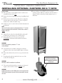
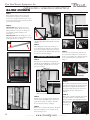
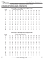
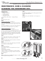
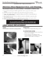
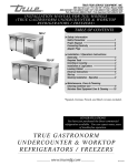
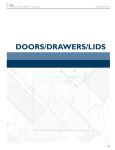
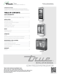
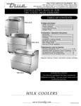
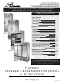
TRUE FOOD SERVICE EQUIPMENT, INC.
2001 East Terra Lane • O’Fallon, Missouri 63366-4434
(636)-240-2400 • FAX (636)272-2408 • INT’L FAX (636)272-7546 • (800)325-6152
Parts Department (800)424-TRUE • Parts Department FAX# (636)272-9471
INSTALLATI O N MA N U AL F O R T-S E R IE S F R E E Z E R /
REFRI GERATO R ( S WIN G AND S LID E D O O R )
TABLE OF CONTENTS
T-23
T-35
TSD-47G
Safety Information
Safety Precautions TSD Do’s and Don’ts Proper Disposal Connecting Electricity Adapter Plugs 1
2
3
4
4
Installation / Operation Instructions
Ownership Required Tools Uncrating Leveling Cabinet Installation of Castors or Optional Legs Installing Optional Castors on a T-12FG Slide Door Operation Instructions Wire Gauge Chart Sealing Cabinet to Floor & Electrical Inst. Start-up LAE Temp Control Shelving Install/Operation & Light Switches Grasslin Defrost Timer (Freezer Units Only) Temperature Control High Altituded Adjustment Field Troubleshooting (Freezer Units Only) Light Cover Install for T-12FG 5
5
5
6
7
8
9
10
11
12
13-21
22
23
24
25-26
27
Maintenance, Care & Cleaning
Cleaning Condenser Coil Stainless Steel Equipment Care & Cleaning Light Bulb Replacement Warranty (U.S.A. & CANADA ONLY!) 28-29
30-31
31
32
*Spanish, German, French, Dutch, and Arabic versions included.
TSD-69
CONGRATULATIONS!
You have just purchased the finest commercial
freezer / refrigerator available. You can expect many
years of trouble-free operation.
T-SERIES
F RE E Z E R / REFRIGERATOR SW I NG
& S LIDE DOOR
............ www.truemfg.com ............
#897001 • WP-106
True Food Service Equipment, Inc.
............ www.truemfg.com ............
True Food Service Equipment, Inc.
SAFETY INFORMATION
How to Maintain Your
Freezer
/ Refrigerator to Receive the Most
Efficient and Successful Operation
You have selected one of the finest commercial refrigeration units made. It is manufactured
under strict quality controls with only the best quality materials available. Your TRUE cooler
when properly maintained will give you many years of trouble-free service.
WARNING!
Use this appliance for its intended purpose as described
in this Owner Manual.
This cabinet contains fluorinated greenhouse gas covered by the Kyoto Protocol
(please refer to cabinet’s inner label for type and volume,
GWP of 134a= 1,300. R404a= 3,800).
SAFETY PRECAUTIONS
When using electrical appliances, basic safety precautions should be followed, including the following:
• This refrigerator must be properly installed
and located in accordance with the Installation
Instructions before it is used.
• Do not allow children to climb, stand or hang on the
shelves in the refrigerator. They could damage the
refrigerator and seriously injure themselves.
• Do not touch the cold surfaces in the freezer
compartment when hands are damp or wet. Skin
may stick to these extremely cold surfaces.
• Do not store or use gasoline or other flammable
vapors and liquids in the vicinity of this or any other
appliance.
• Keep fingers out of the “pinch point” areas;
clearances between the doors and between the doors
and cabinet are necessarily small; be careful closing
doors when children are in the area.
1
NOTE
We strongly recommend that any servicing be performed by
a qualified individual.
• Unplug the refrigerator before cleaning and making repairs.
• Setting temperature controls to the 0 position does
not remove power to the light circuit, perimeter
heaters, or evaporator fans.
............ www.truemfg.com ............
1
True Food Service Equipment, Inc.
2
............ www.truemfg.com ............
2
True Food Service Equipment, Inc.
SAFETY INFORMATION
DANGER!
RISK OF CHILD ENTRAPMENT
PROPER DISPOSAL OF THE FREEZER /
REFRIGERATOR
Child entrapment and suffocation are not problems
of the past. Junked or abandoned refrigerators are still
dangerous… even if they will sit for “just a few days.” If
you are getting rid of your old refrigerator, please follow
the instructions below to help prevent accidents.
Before You Throw Away Your Old Refrigerator or
Freezer:
• Take off the doors.
• Leave the shelves in place so that children may not
easily climb inside.
Refrigerant Disposal
Your old refrigerator may have a cooling system
that uses “Ozone Depleting ” chemicals. If you are
throwing away your old refrigerator, make sure the
refrigerant is removed for proper disposal by a
qualified service technician. If you intentionally
release any refrigerants you can be subject to
fines and imprisonment under provisions of the
environmental regulations.
USE OF EXTENSION CORDS
NEVER USE AN EXTENSION CORD! TRUE will not warranty any refrigerator that has been connected to an extension cord.
3
............ www.truemfg.com ............
3
True Food Service Equipment, Inc.
SAFETY INFORMATION
WARNING!
HOW TO CONNECT ELECTRICITY
Do not, under any circumstances, cut or remove the ground prong from the power cord.
For personal safety, this appliance must be properly grounded.
The power cord of this appliance is equipped with a
grounding plug which mates with a standard grounding wall
outlet to minimize the possibility of electric shock hazard from
this appliance.
Have the wall outlet and circuit checked by a qualified
electrician to make sure the outlet is properly grounded.
If the outlet is a standard 2-prong outlet, it is your personal
responsibility and obligation to have it replaced with the
properly grounded wall outlet.
The refrigerator should always be plugged into it’s own
individual electrical circuit, which has a voltage rating that
matches the rating plate.
This provides the best performance and also prevents
overloading building wiring circuits which could cause a fire
hazard from overheated wires.
Never unplug your refrigerator by pulling on the power cord.
Always grip plug firmly and pull straight out from the outlet.
Repair or replace immediately all power cords that have
become frayed or otherwise damaged. Do not use a cord that
shows cracks or abrasion damage along its length or at either
end.
When removing the refrigerator away from the wall, be
careful not to roll over or damage the power cord.
USE OF ADAPTER PLUGS
NEVER USE AN ADAPTER PLUG! Because of potential safety hazards under certain conditions, we strongly recommend
against the use of an adapter plug.
(North America Use Only!)
NEMA plugs
TRUE uses these types of plugs. If you do not have
the right outlet have a certified electrician install
the correct power source.
T-72F WIRING CHANGES
(110V Application Only)
Previous design: 4 prong plug NEMA 14-20R - 4 wire circuit (see image 1).
Current design: 3 prong plug NEMA 5-20R - 3 wire circuit (see image 2).
WIRING CONVERSION
At Receptacle Box
1. Turn breaker off
2. Disconnect all wires from receptacle
3. Insulate red wire (tape or wire nut)
4. Connect black, white, and green wires to 3
prong plug NEMA 5-20R per instructions
on receptacle
1
2
NOTE: It is the customer’s responsibility to make sure receptacle wiring
meets all local electrical codes. TRUE recommends hiring a licensed qualified
electrician to make this change.
4
At Breaker Panel
1. With breaker turned off, remove wires
2. Remove double pole breaker
3. Install single pole breaker
4. Connect black wire to breaker
5. Insulate red wire
6. Turn breaker back on
............ www.truemfg.com ............
4
True Food Service Equipment, Inc.
INSTALLATION / OPERATION INSTRUCTIONS
INSTALLATION / OPERATION INSTRUCTIONS
OWNERSHIP
To ensure that your unit works properly from the first
day, it must be installed properly. We highly recommend
a trained refrigeration mechanic and electrician install
your TRUE equipment. The cost of a professional
installation is money well spent.
Before you start to install your TRUE unit, carefully
inspect it for freight damage. If damage is discovered,
immediately file a claim with the delivery freight carrier.
TRUE is not responsible for damage incurred during
shipment.
REQUIRED TOOLS
• Adjustable Wrench
• Phillips Head Screwdriver
•Level
UNCRATING
NOTE
Units with a solar thermometer will experience a 15 second delay
after exposed to light before it reads the proper temperature.
The following procedure is recommended for uncrating the
unit:
A. Remove the outer packaging, (cardboard and bubbles or
styrofoam corners and clear plastic). Inspect for concealed
damage. Again, immediately file a claim with the freight
carrier if there is damage.
B. Move your unit as close to the final location as possible
before removing the wooden skid.
5
C. Remove door bracket on swinging glass door models (see
image 1-2). Sliding glass door models contain shipping
blocks (three for each door). Remove the two styrofoam
blocks taped to the top of the door tracks (see image 3).
The shipping blocks are orange in color and by opening
the door a little the blocks can be removed (see images
4-6). Do not throw the bracket or blocks away. For future
cabinet movement the bracket and blocks will need to be
installed so the glass door does not receive any damage.
(See image for bracket and shipping block removal)
NOTE
Keys for coolers with door locks are located in warranty packets.
1
2
3
4
5
6
............ www.truemfg.com ............
5
True Food Service Equipment, Inc.
LOCATING
INSTALLATION / OPERATION INSTRUCTIONS
A. Remove louver from the front of cabinet (see page 17 for
louver grill removal / reinstallation) and backguard (if
applicable) from rear of cabinet.
B. Skid bolts are located in each of 4 corners inside cabinet
bottom. (See photo A).
C. Remove skid bolts. (See photo B).
D. Cut straps if applicable. (See photo C).
E. Carefully lift cabinet off of skid.
A
B
Removing skid from bottom
of cabinet.
C
LEVELING
A. Set unit in its final location. Be sure there is adequate
ventilation in your room. Under extreme heat
conditions, (100°F+, 38°C+), you may want to install
an exhaust fan.
WARNING
Warranty is void if ventilation is insufficient.
WARNING
Cabinet warranties are void if OEM power cord is tampered
with. TRUE will not warranty any units that are connected to
an extension cord.
P
B. Proper leveling of your TRUE cooler is critical to
operating success (for non-mobile models). Effective
condensate removal and door operation will be
effected by leveling.
C. The cooler should be leveled front to back and side
to side with a level.
D. Ensure that the drain hose or hoses are positioned in
the pan.
E. Free plug and cord from inside the lower rear of the
cooler (do not plug in).
F. The unit should be placed close enough to the
electrical supply so that extension cords are never
used.
REMOTE UNITS (This section applies to remotes only!)
• Remote cabinets must be ordered as remote. • Contact TRUE Technical Service for BTU We do not recommend converting from a requirements.
standard self contained to remote system.
• No wiring necessary between cabinet and • All remote cabinets must be hard wired.
condensing unit.
• No castors available.
• All remote condensing units purchased from TRUE
are
208/230
volts
single
phase.
• All remote cabinets come standard using 404A refrigerant.
If you have any questions regarding this section, please
call TRUE at 1-(800)-325-6152.
• All remote units come standard with expansion valve, liquid line solenoid, heated condensate pan, and defrost timer when applicable.
6
6
............ www.truemfg.com ............
True Food Service Equipment, Inc.
INSTALLATION / OPERATION INSTRUCTIONS
INSTALLATION OF CASTORS OR OPTIONAL LEGS
Important Safeguard for installation of leg/castor (Images 1-5 demonstrate procedure)
Securing Castors and Legs
To obtain maximum strength and stability of the unit,
it is important that you make sure each castor is secure.
Optional legs are hand-tightened securely against the
lower rail assembly see image 4-5. The bearing race on
the castor or the top edge of the leg must make firm
contact with the rail.
Unit leveling
Four leveling shims have been provided for leveling
castored units positioned on uneven floors. Shims must
be positioned between rail end and bearing race.
A. Turn the bearing race counter-clockwise until the
cabinet is level. Level front to back and side to side.
(diagonally)
1
Thread castor into the underside of
cabinet frame rail.
B. Install the desired number of shims, making sure the
slot of the shim is in contact with the threaded stem
of the castor. (See image 2)
C. If more than one shim is used, turn the slot at a 90°
angle so they are not in line.
D. Turn the bearing race clockwise to tighten and secure
the castor by tightening the anchoring bolt with a
3/4 inch open-end wrench or the tool provided.
(See image 3)
CAUTION
To avoid damage to lower rail assembly, slowly raise unit to
upright position.
NOTE
Open holes located on the cross members of the frame rail
should be plugged before unit is in use.
2
4
3
For leveling, insert the shim
between the castor and frame rail.
Use the tool provided to tighten
the castor into place.
Lower Rail
Assembly
Thread leg into cabinet bottom
frame rail.
Lower Rail Assembly
Rail End
Rail End
5
Snug Fit
Here
Bearing
Race
Snug Fit
Here
Leveling Shim
The end of the leg is adjustable
to easy leveling.
Leg
7
Castor
............ www.truemfg.com ............
7
True Food Service Equipment, Inc.
INSTALLATION / OPERATION INSTRUCTIONS
INSTALLING OPTIONAL CASTORS ON A T-12FG
Final Location
A. Place styrofoam corners behind cooler for cushion and
carefully tilt unit on it’s back.
B. Remove the louvered grill by removing four phillips-head
screws.
C. Remove the four bolts from the skid with an adjustable
wrench, and locate the four castors. Castors are placed
inside cooler, within the bubble wrap.
D. Install one castor in each of the four female threaded areas
as indicated.
NOTE
Two out of the four castors are designated with an “F” for front.
These are provided with hand-brakes. Position these castors in
FRONT of the unit.
K. Proper leveling of your TRUE cooler is critical to
operating success. Effective condensate removal and door
operation will be effected by leveling. Adjust castors or
add shims.
E. When all castors have been threaded fully, replace grill
and lift unit; positioning it into its final location.
F. Ensure that the two front castors are positioned
FORWARD as illustrated and locked down with the
hand-brakes.
WARNING
Unit may tip forward if procedure “F” is not
strictly followed.
G. Units final location should be adequately ventilated.
Conditions where heat exceeds 100ºF require an exhaust
fan.
H. Ensure that the drain hose for hoses are positioned in the
pan.
I. Free plug and cord from inside the lower rear of the
cooler (Do Not Plug In.)
WARNING
Warranty is VOID if ventilation is insufficient.
POSITIONING OF THE
CASTOR IS CRITICAL.
ORIENT THE CASTOR IN
THE FORWARD POSITION
AS SHOWN
J. The unit should be placed close enough to the electrical
supply so that extension cords are NEVER used.
WARNING
Cabinet warranties are void if OEM power cord is tampered with.
TRUE will not warranty any units that are connected to an extension cord.
8
............ www.truemfg.com ............
8
True Food Service Equipment, Inc.
INSTALLATION / OPERATION INSTRUCTIONS
SLIDE DOORS
TRUE Logo
STEP 1
Before removing slide door do not use the side
latch. Tension on the door cord is needed to
execute these operation instructions. Doors can
not be removed unless placed in specific locations
stated in these instructions.
STEP 2
Two Door Units: Slide the front door so it is
centered on the cabinet. The door can not be
removed unless it is centered. See image 1 for
door channel openings and image 2 for
centering door.
Three Door Units: Slide the middle door to the
right side so the glass is centered with the left edge
of the right side door. See image 3.
1
(Two Door Units ONLY)
4
(Three Door Units ONLY)
Gasket fasten to door bottom assures door will
remain in track when unit is placed on uneven
surface.
STEP 3
After centering the door lift it up and tilt top of
door towards the back of the unit so the rollers are
out of the top channel. Swing the bottom of the
door out of the bottom channel. Then remove the
door and set it down. See image 4.
(TWO DOOR UNITS SKIP TO STEP 6)
STEP 4
Slide right door to the left so left edge lines up
with the left edge of TRUE Logo located above the
door. See image 5. Then lift door out of track
same way as image 4.
CENTERED DOOR
6
7
STEP 7
Let the door cord slowly retract back into the
door side channel. The knot tied at the end of
the door cord will keep the cord from retracting
all the way back into the door channel. See
image 9.
TRUE Logo
9
2
Door Cord
Knot
P-Clip keeps cord
in-place (prevents
cord damage).
TO ADJUST SLIDE DOOR
(Two Door Units ONLY)
5
(Three Door Units ONLY)
CENTER DOOR
3
(Three Door Units ONLY)
9
8
STEP 5
Slide left door to the right so right edge lines up
with the end of the TRUE Logo located at the
top of the door frame. See image 6. Then lift
door out of track same way as image 4.
STEP 6
Remove door cord from roller bracket. The black
plastic tab holding the door cord slides out the
back. See images 7 & 8.
STEP 1
After cabinet is installed in a final location and
correctly leveled check for any openings when the
slide doors are completely closed. If there are
any gaps/openings between the closed doors
and cabinet, the doors will need to be
adjusted.
STEP 2
Using a 7/16” wrench or adjustable wrench and
1/8” allen wrench loosen roller and move
along slotted hole. After adjustment has been
made tighten the
roller into place.
See image 10.
............ www.truemfg.com ............
10
9
True Food Service Equipment, Inc.
INSTALLATION / OPERATION INSTRUCTIONS
CONDUCTORS AND CIRCUITS
Wire Gauge for 2% Voltage Drop in Supply Circuits
115 Volt Distance In Feet To Center of Load
Amps 2030405060708090100120
140160
2
141414141414141414141414
3
141414141414141414141412
4
141414141414141414121212
5
141414141414141212121010
6
14
14
14
14
14
14
12
12
12
10
10
10
7
8
9
10
12
1414141414121212101010
14141414121212101010 8
141414121212101010 8 8
141414121210101010 8 8
14
14
12
12
10
10
10
8
8
8
8
8
8
8
8
6
14
16
18
20
25
14
14
12
10
10
10
14
12
12
10
10
8
14121010 8 8
14
12
10
10
8
8
12
10
10
8
8
6
8
8
8
8
6
8
8
8
6
6
8
8
8
6
6
6
6
8
6
5
6
6
8
5
4
6
6
5
5
4
12
10
10
10
10
6
5
5
4
4
6
5
4
4
3
5
4
4
3
3
4
4
3
3
2
4
3
2
2
1
3
2
2
1
1
30
35
40
45
50
10
10
8
8
8
8
8
8
6
6
8
6
6
6
6
6
6
6
6
5
6
6
5
5
4
Wire Gauge for 2% Voltage Drop in Supply Circuits
230 VoltsDistance In Feet To Center of Load
Amps 2030405060708090100120
140160
5
141414141414141414141414
6
14
14
14
14
14
14
14
14
14
14
14
12
7
141414141414141414141212
8
141414141414141414121212
9
141414141414141412121210
10
10
12
14
16
18
141414141414141212121010
141414141414121212101010
1414141414121212101010 8
14
14
14
14
12
12
12
10
10
10
8
8
141414121212101010 8 8 8
20
25
30
35
40
141414121010101010
14
14
12
12
10
10
10
10
8
14
12
12
10
10
10
8
8
8
14
12
10
10
10
8
8
8
8
14
12
10
10
8
8
8
6
6
8
8
6
6
6
8
6
6
6
5
8
6
6
5
5
12
12
10
10
10
10
5
4
4
3
3
2
4
4
2
2
1
1
4
3
2
2
1
1
50
60
70
80
90
100
10
10
10
8
8
8
10
8
8
8
6
6
8
6
6
6
6
6
6
6
6
6
5
5
6
6
6
5
5
4
6
6
5
5
4
4
6
6
5
4
4
3
6
5
4
4
3
3
............ www.truemfg.com ............
10
True Food Service Equipment, Inc.
INSTALLATION / OPERATION INSTRUCTIONS
ELECTRICAL INSTRUCTIONS
A. Before your new unit is connected to a power supply,
check the incoming voltage with a voltmeter. If
anything less than 100% of the rated voltage for
operation is noted, correct immediately.
B. All units are equipped with a service cord, and must
be powered at proper operating voltage at all times.
Refer to cabinet data plate for this voltage.
TRUE requires that a sole use circuit be dedicated for the
unit. Failure to do so voids warranty.
WARNING
Compressor warranties are void if compressor burns out
due to low voltage.
WARNING
Power supply cord ground should not be removed!
NOTE
To reference wiring diagram - Remove front louvered grill,
wiring diagram is positioned on the inside cabinet wall.
SEALING CABINET TO FLOOR
Step 1 - Position Cabinet
Allow one inch between the wall and rear of the
refrigerator to assure proper ventilation. For freezers
3 inches between the wall and rear of the cabinet will
assure proper ventilation.
Step 2 - Level Cabinet
Cabinet should be level, side to side and front to back.
Place a carpenter’s level in the interior floor in four
places:
A. Position level in the inside floor of the unit near the
doors. (Level should be parallel to cabinet front).
Level cabinet.
B. Position level at the inside rear of cabinet. (Again
level should be placed parallel to cabinet back).
C. Perform similar procedures to steps a & b by placing
the level on inside floor (left and right sides - parallel
to the depth of the cooler). Level cabinet.
Step 3
Draw an outline on the base on the floor.
Step 4
Raise and block the front side of the cabinet.
Step 5
Apply a bead of “NSF Approved Sealant”, (see list
below), To floor on half inch inside the outline drawn.
The bead must be heavy enough to seal the entire cabinet
surface when it is down on the sealant.
11
Step 6
Raise and block the rear of the cabinet
Step 7
Apply sealant on floor as outline in Step 5. on other
three sides.
Step 8
Examine to see that cabinet is sealed to floor around
entire perimeter.
NOTE
Asphalt floors are very susceptible to chemical attack. A
layer of tape on the floor prior to applyingthe sealant will
protect the floor.
NSF Approved Sealants:
1. Minnesota Mining #ECU800 Caulk
2. Minnesota Mining #ECU2185 Caulk
3. Minnesota Mining #ECU1055 Bead
4. Minnesota Mining #ECU1202 Bead
5. Armstrong Cork - Rubber Caulk
6. Products Research Co. #5000 Rubber Caulk
7. G.E. Silicone Sealer
8. Dow Corning Silicone Sealer
............ www.truemfg.com ............
11
True Food Service Equipment, Inc.
INSTALLATION / OPERATION INSTRUCTIONS
FREEZERS ONLY! (COMPRESSOR BAND REMOVAL)
PLEASE CHECK YOUR COMPRESSOR. IF THERE IS A SHIPPING BAND, PLEASE REMOVE.
WARNING
COMPRESSOR BAND MUST BE REMOVED BEFORE UNIT IS
CONNECTED TO POWER SUPPLY.
The metal band can be reached from the rear of the unit.
A pair of tin snips will cut through the band. Once the
band is located and removed. You may proceed with the
installation of your new equipment. (See image to the
right).
Cutting band that is around compressor
STARTUP
A. The compressor is ready to operate. Plug in the
cooler.
B. Temperature control set at No. 4 position gives
refrigerators an approximate temperature of 35°F.
Allow unit to function several hours, completely
cooling cabinet before changing the control setting.
C. Excessive tampering with the control could lead to
service difficulties. Should it ever become necessary
to replace temperature control, be sure it is ordered
from your TRUE dealer or recommended service
agent.
D. Good air flow in your TRUE unit is critical. Be
careful to load product so that it neither presses
against the back wall, nor comes within four inches
of the evaporator housing. Refrigerated air off the
coil must circulate down the back wall.
12
NOTE
If the cooler is disconnected or shut off, wait five minutes
before starting again.
RECOMMENDATION
Before loading product we recommend you run your TRUE
unit empty for two to three days. This allows you to be sure
electrical wiring and installation are correct and no shipping
damage has occurred. Remember, our factory warranty
does not cover product loss!
REPLACEMENT PARTS
TRUE maintains a record of the cabinet serial number
for your cooler. If at any time during the life of your
cooler, a part is needed, you may obtain this part by
furnishing the model number and serial number to the
company from whom you purchased the cooler. Call
Toll-Free: (800)-424-TRUE (Direct to Parts Department).
(800)-325-6152 (U.S.A. & Canada only) or call:
(636)-240-2400.
............ www.truemfg.com ............
12
True Food Service Equipment, Inc.
IF YOUR CABINET IS BUILT WITH THIS
TEMPERATURE CONTROL, PLEASE SEE THE
FOLLOWING INSTRUCTIONS.
For proper operation, it is important to set correct
time of day at time of cabinet installation.
13
............ www.truemfg.com ............
13
True Food Service Equipment, Inc.
LAE CONTROL FOR T-SERIES
FREEZERS SEQUENCE OF OPERATION
1. Cabinet is plugged in.
a. Display will illuminate.
b. Interior light will illuminate on glass door models only. (If lights do not come on please see instructions on following page(s).) Solid door cabinet lights are controlled by door switch.
2. After the LAE control preprogrammed time delay of 3 minutes, the compressor and evaporator fan(s) will start if
the control is calling for cooling.
a. Control may be already pre-programmed from the factory so at the start of every compressor cycle or during a defrost cycle, the condenser fan(s) will reverse for 30 seconds to blow dirt off the condensing coil.
3. The LAE control will cycle the compressor but may also cycle evaporator fan(s) on and off together
determined by the Set-Point and Differential temperatures. (If the Set-Point needs to be changed due to
conditions please see instructions on the following page(s).)
a. The Set-Point is the preprogrammed temperature which shuts off the compressor.
b. The Differential is the preprogrammed temperature that is added to the Set-Point temperature that will start the compressor.
Example: If the Set-Point is -9°F/-23°C and the Differential is 10°F/5°C
(Set-Point) -9°F + 10 (Differential) = 1°F
Or
(Set-Point) -23°C + 5 (Differential) = -18°C
The compressor and evaporator fan(s) will cycle off -9°F/-23°C
and back on at 1°F/-18°C
4. The LAE control may be preprogrammed to initiate defrost by interval or at specific times of day. (If additional
Defrost Intervals / Cycles are needed or a manual defrost is required due to conditions please see instructions
on the following page(s).)
a. At this time the “dEF” will appear on the display and compressor will turn off until a preprogrammed temperature or duration is reached. During this time for freezers only, evaporator fan(s) will also turn off and the coil heater and drain tube heaters will also be energized.
b. After the preprogrammed temperature or duration for defrost has been reached there may be a short delay for both the compressor and evaporator fans to restart. At this time “dEF” may still appear on the display for a short time.
True Manufacturing recommends that ONLY the Set-Point and/or
Defrost Interval / Cycles may be adjusted due to certain conditions.
This sequence is NOT model specific.
If you have any questions, please contact the Technical Service Department.
Phone: 800-325-6152 • Email: [email protected]
14
............ www.truemfg.com ............
14
True Food Service Equipment, Inc.
LAE Electronic Control
LAE Control Icons
Compressor
Running
Evaporator Fan
Running
Cabinet in Defrost
Activation of 2nd
Parameter Set - NA
Alarm - NA
Info/Set Point
Button
Manual Defrost/
Down Button
Manual Activation/
Up Button
Stand-By
Button
LOCKING & UNLOCKING LAE CONTROLLER
WHY:
LOCKING OF CONTROL IS NECESSARY TO PREVENT
CHANGES TO PROGRAM THAT MAY AFFECT CABINET
OPERATION
1
HOW:
A. To change lock setting press and release the info button
. “t1” will appear. See image 1.
Press and release the up button
appears. See image 2.
2
until “Loc”
press
B. While pressing and holding the info button
the up
or down
button to change the lock
settings. If “no” appears, the controller is unlocked. If “yes”
appears, the controller is locked. See images 3 and 4.
C. Once the lock setting has been set correctly release the
info button
.
Wait 5 seconds for the display to show temperature.
See image 5.
3
Image 3:
If “no” appears
on screen,
the controller
is unlocked.
4
Image 4:
If “yes” appears
on screen,
the controller
is locked.
5
15
............ www.truemfg.com ............
15
True Food Service Equipment, Inc.
LAE Electronic Control
LAE Control Icons
Compressor
Running
Evaporator Fan
Running
Cabinet in Defrost
Activation of 2nd
Parameter Set - NA
Alarm - NA
Info/Set Point
Button
Manual Defrost/
Down Button
Manual Activation/
Up Button
Stand-By
Button
HOW TO TURN GLASS DOOR MODEL
LIGHTS ON/OFF
May need to unlock control.
WHY:
LIGHT MAY BE CONTROLLED BY LAE CONTROLLER OR
INTERIOR LIGHT SWITCH.
ON Position
HOW:
A. To control interior/sign lights by the LAE Controller,
press and release the “Manual Activation”
button.
B. To control interior/sign lights by the interior door
switch, depress the rocker switch to the “ON” position.
Light Switch is located on inside top right of the
ceiling.
(Solid Door models lights are controlled by a door switch)
16
............ www.truemfg.com ............
16
True Food Service Equipment, Inc.
LAE Electronic Control
LAE Control Icons
Compressor
Running
Evaporator Fan
Running
Cabinet in Defrost
Activation of 2nd
Parameter Set - NA
Alarm - NA
Info/Set Point
Button
Manual Defrost/
Down Button
Manual Activation/
Up Button
Stand-By
Button
SETTING TIME OF DAY
May need to unlock control. Does not adjust for daylight savings time.
This is only necessary if the defrost mode parameter (DFM) is set for “RTC”.
WHY:
TO MAKE SURE THE CABINET DOES NOT INITIATE
DEFROST & GET WARM DURING TIMES OF HIGH USAGE.
1
Control may be designed to initiate defrost at specific
times of the day.
HOW:
A. To change the time of day, press and release the info
button
. “t1” will appear.
Press the up button
See image 1.
2
until “min” appears.
, press
B. While pressing and holding the info button
the up
or down
button to change the clock
minutes. See image 2.
C. Once the minutes have been set correctly, release the
info button
and “hrs” will appear on the display.
See image 3.
D. While pressing and holding the info button
, press
the up
or down
button to change the clock
hours. See image 4.
Note: When changing the clock hour, the clock will be
displayed in 24 hour format ranging from 0-23.
E. Once the hour has been set correctly, release the info
button
.
3
4
5
Wait 5 seconds for the display to show temperature.
See image 5.
17
............ www.truemfg.com ............
17
True Food Service Equipment, Inc.
LAE Electronic Control
LAE Control Icons
Compressor
Running
Evaporator Fan
Running
Cabinet in Defrost
Activation of 2nd
Parameter Set - NA
Alarm - NA
Info/Set Point
Button
Manual Defrost/
Down Button
Manual Activation/
Up Button
Stand-By
Button
HOW TO CHANGE THE “SET POINT”
May need to unlock control.
WHY:
THE SET POINT IS THE TEMPERATURE AT WHICH THE
COMPRESSOR WILL SHUT OFF.
1
Please note that the “set point” IS NOT the cabinet
holding temperature.
HOW:
A. To see the set point, press and hold the info button.
See image 1.
2
,
B. While still holding the info button
press the up
or down
button to change
the “set point”.
C. Once the “set point” has been set correctly release the
info button
.
The display will show temperature. See image 2.
18
............ www.truemfg.com ............
18
True Food Service Equipment, Inc.
LAE Electronic Control
LAE Control Icons
Compressor
Running
Evaporator Fan
Running
Cabinet in Defrost
Activation of 2nd
Parameter Set - NA
Alarm - NA
Info/Set Point
Button
Manual Defrost/
Down Button
Manual Activation/
Up Button
Stand-By
Button
HOW TO INITIATE A MANUAL DEFROST
May need to unlock control.
WHY:
A ONE TIME ADDITIONAL DEFROST MAY BE NECESSARY
TO CLEAR ACCUMULATED FROST/ICE FROM EVAPORATOR
COIL.
HOW:
The method to initiate a manual defrost is determined by
the Defrost Mode Parameter “DTM” preprogrammed in
the controller.
A. REGULAR TIME DEFROST (TIM)
If controller is preprogrammed for “TIM”, press and
release the Manual Defrost button until “dEF” appears.
B. REAL TIME CLOCK (RTC)
If controller is preprogrammed for “RTC” press the and
hold the Manual Defrost button for 5 seconds until
“dh1” appears. Release the Manual Defrost button and
then press and hold for an additional 5 seconds until
“dEF” appears.
DEFROST WILL ONLY TERMINATE ONCE A SPECIFIC PRESET
TEMPERATURE OR A PRESET TIME DURATION IS REACHED.
19
............ www.truemfg.com ............
19
True Food Service Equipment, Inc.
LAE Electronic Control
LAE Control Icons
Compressor
Running
Evaporator Fan
Running
Cabinet in Defrost
Activation of 2nd
Parameter Set - NA
Alarm - NA
Info/Set Point
Button
Manual Defrost/
Down Button
Manual Activation/
Up Button
Stand-By
Button
HOW TO CHANGE “DEFROST
INTERVALS”
May need to unlock control.
This can only be changed if defrost mode parameter “DFM” is set for “TIM”.
WHY:
THE DEFROST INTERVAL IS THE TIME DURATION BETWEEN
DEFROST CYCLES.
1
The Defrost Interval time starts when the cabinet is supplied
power or after a manual defrost.
2
HOW:
A. To see the set point, press and hold the info button
and the stand-by button
at the same time.
“ScL” will appear. See image 1.
B. Push the up button
See image 2.
until “dFt” appears.
3
C. Press and hold the info button
to see the
“defrost interval time”. See image 3.
D. While pressing and holding the info button
,
press the up or down button to change the “defrost
interval times” (higher the number the less frequent the
cabinet will defrost).
4
E. Once the “defrost interval time” has been changed,
release the info button
.
Wait 30 seconds for the display to show temperature.
See image 4.
20
............ www.truemfg.com ............
20
True Food Service Equipment, Inc.
LAE Electronic Control
LAE Control Icons
Compressor
Running
Evaporator Fan
Running
Cabinet in Defrost
Activation of 2nd
Parameter Set - NA
Alarm - NA
Info/Set Point
Button
Manual Defrost/
Down Button
Manual Activation/
Up Button
Stand-By
Button
HOW TO CHANGE A “DEFROST CYCLE”
May need to unlock control.
This can only be changed if defrost mode parameter (DFM) is set for “RTC”.
1
WHY:
THE DEFROST TIME IS THE TIME OF DAY DEFROST CYCLES ARE INITIATED.
Time of Day must be set ensure that factory set defrost times are
occur at the correct times. By adding a cycle you will be adding an
extra specific defrost start time.
2
HOW:
A. To see the defrost times press and hold the info button
and
the stand-by button
at the same time.. “ScL” will appear.
See image 1.
B. Push the “up” button
3
until “dh1” appears. See image 2.
C. Press and hold the info button
to see the “defrost time”.
See image 3.
Note: Clock times are displayed in 24 hour format ranging from 0-23.5.
4
D. Release and push the info button
to scroll “dh1” - “dh6”
which show the factory pre-set defrost times. See image 4.
Additional time of day may be added when the time for defrost
shows “---”.
5
E. While pressing and holding the info button
press the up or
down button to change “defrost time”. See image 5.
F. Once the “defrost time” has been added release the info
button.
Wait 30 seconds for the display to show temperature. See image 6.
6
ALL OTHER SETTINGS ARE FACTORY PRE-SET AND SHOULD NOT BE CHANGED.
If you have any questions, please call TRUE technical service.
Phone: 800-325-6152 • Email: [email protected]
21
............ www.truemfg.com ............
21
True Food Service Equipment, Inc.
INSTALLATION / OPERATION INSTRUCTIONS
SHELVING INSTALLATION / OPERATION &
LIGHT SWITCH LOCATION
WARNING
Do not use pliers or any crimping tools when
installing shelf clips. Altering shelf clips in any
way can lead to shelving instability.
3
1
You may need to squeeze or twist the bottom
of the shelf clip to install)
(Installing top tab of shelf clip)
Step 2
Bottom tab of the shelf clip will fit tightly.
You may need to squeeze or twist the
bottom of the shelf clip to install. (See
image 2 & 3).
4
(Shelf clip installation complete)
Step 3
After installation, the shelf clip will fit snug
into the shelf standard. The shelf clip should
not be loose or able to wiggle out of the
shelf standard.
For Proper Shelf Clip Installation Please
Read The Following Instructions.
Step 1
Shelf clips are to be installed into the shelf
standards next to the labels on the interior
cabinet wall. This label can be seen in
images 1-4. Install the top tab of the shelf
clip into the proper hole. Push up on the
bottom of the clip. (See image 1).
2
Shelf Installation Tips
(Installing bottom of the shelf clip)
1. Install all the shelf clips before installing
the shelves.
2. Start at the bottom in terms of shelf
installation and work your way up.
3. Always lay the back of each shelf down
on the rear clips before the front.
T-Series
& GDM-5
Airflow
Guard
SHELF & ORGANIZER INSTALLATION:
Step 1
A. Hook shelf clips onto shelf standards. (see illustration).
B. Position all four shelf clips equal in distance from the
floor for flat shelves.
WIRE SHELVES
Wire shelves are oriented so that cross support bars are facing down.
NOTE
T-Series models include an airflow guard on the rear of shelves to
maintain an air space at the rear of the cabinet. (see illustration).
Step 2
Place shelves on shelf clips making sure all corners are seated
properly.
22
Shelf
Shelf
Shelf
Clip
Pillaster
LIGHT SWITCH LOCATION:
Light switch location depends upon the T-Series model. Most
T-Series models will have the light switch located inside the unit on
the right side of the ceiling. Most instances the switch is located next
to the temperature control. Some models have the switch located on
the right side of the evaporator housing along the interior ceiling.
............ www.truemfg.com ............
22
True Food Service Equipment, Inc.
INSTALLATION / OPERATION INSTRUCTIONS
FREEZERS DEFROST TIME CLOCK OPERATION
T-19F, T-19FZ, T-23F
Defrost System!
ALL OTHER UNITS.
Defrost System!
Outer most dial.
White tabs represent
15 minutes of defrost
time.
This defrost system is time initiated / time
This defrost system is temperature
terminated. The refrigeration system does not terminated, however the time clock has been
restart until the defrost cycle has timed out.
designed with a time termination back-up.
REQUIRED TOOLS:
•
•
REQUIRED TOOLS:
• Phillips Screwdriver
• 1/4” Nut Driver or Socket
Phillips Screwdriver
1/4” Nut Driver or Socket
Time of day.
Inner most dial.
Locating The Defrost Timer:
Locating The Defrost Timer:
See page 2 for removing louver grill
* T-23F-2 / T-23DT Grill must be reattached instructions.
correctly for proper operation.
See page 2 for removing louver grill instructions.
Single Door Models:
Defrost timer is located in the lower right corner
behind the louvered grill (inside galvanized
electrical box).
Outer most dial. White tabs represent 15 minutes of
defrost time.
Two Door Models:
Defrost timer is located in the middle of the
cabinet, behind the louvered grill. Timer is
mounted to the left of the centered ballast
box (Inside of gray timer box).
Three Door Models:
Defrost timer is located on the left upright
post behind the louvered grill (Inside of gray
timer box).
Setting the timer:
(UNPLUG UNIT FROM
POWER SUPPLY!)
DO NOT SET THE TIME BY
ROTATING THE “OUTER” DIAL.
Turn the minute hand clockwise until the
time of day on the outer dial is aligned with
the triangle marker on the inner dial (two
o’clock position).
Factory setting 2 am, 8 am, 2 pm, 8 pm. 15
minutes in length. TRUE recommends maximum
15 minute defrost cycles & minimum 4 defrost
periods per day.
Setting the timer:
(UNPLUG UNIT FROM
POWER SUPPLY!)
DO NOT SET THE TIME BY
ROTATING THE “OUTER” DIAL.
Turn the minute hand clockwise until the time of
day on the outer dial is aligned with the triangle
marker on the inner dial (two o’clock position).
The following procedure may be followed to
customize your needs.
The following procedure may be followed to
customize your needs.
STEP 1
In order to program the time to begin the
defrost cycle, flip the white tabs out to set the
defrost time. To eliminate a defrost time flip
the white tabs back toward the center of the
Defrost Timer.
NOTE
TRUE recommends a minimum 30 minute (2
tabs) defrost cycle three times per day.
(Except T-19F/19FZ/23F).
Defrost Timer Box Image 1
All models except T-19F, T-19FZ, T-23F.
The white tabs located on the outmost area
of the time clock have been factory set for
(6:00 a.m., 2:00 p.m., and 10:00 p.m.).
Each tab represents 15 minutes of defrost
time. Notice that at each defrost time two
white tabs are set for 15 minutes each for a
total of 30 minutes of defrost.
WARNING:
High usage, high temperature, and
high humidity may require additional
defrost settings per day. Once clock
is set & grill is correctly reinstalled
cabinet can be plugged in.
STEP 1
In order to program the time to begin the defrost
cycle, flip the white tabs out to set the defrost time.
To eliminate a defrost time flip the white tabs back
toward the center of the Defrost Timer.
23
............ www.truemfg.com ............
23
True Food Service Equipment, Inc.
INSTALLATION / OPERATION INSTRUCTIONS
TEMPERATURE CONTROL ADJUSTMENT FOR
HIGH ALTITUDE ONLY!
TERMS:
STEP 4
Cut-out - Temperature sensed
by the controller that shuts the
compressor off.
For high elevation installations, it
may be necessary to “warm-up” the
set points. To make the adjustment,
insert the appropriate tool in each
adjustment screw and turn 1/4 of a
revolution clockwise (to the right).
This procedure will adjust both
the cut-in and cut-out about 2°F
warmer.
Cut-in - Temperature sensed by the
controller that turns the compressor
on.
REQUIRED TOOLS
• Phillips Head Screwdriver
• 5/64” or 2 mm Allen Wrench
• T-7 Torx Wrench
STEP 1
STEP 5
Make sure to reconnect the pink
wire to the proper spade
terminal when reinstalling.
Unplug the cooler.
STEP 2
Remove the screws that secure the
temperature control to the inset box
lower left side of the cabinet (when
facing the front of the cabinet).
Danfoss Temperature Control (High Altitude Only!)
STEP 3
Cut-out Adjustment Screw Allen (5/64”
or 2 mm) (clockwise for warmer)
Pull out gently from cabinet.
NOTE
Mechanical temperature
controllers are affected when
functioning at high altitude. The
cut-in and cut-out
temperatures will be colder than
when the controller functions closer
to sea level.
24
Cut-in Adjustment Screw Torx (T-7)
(clockwise for warmer)
Compressor Connection (pink)
Compressor Connection (pink)
............ www.truemfg.com ............
24
True Food Service Equipment, Inc.
INSTALLATION / OPERATION INSTRUCTIONS
IF THE COMPRESSOR WILL NOT RUN
1. If there is no voltage at the compressor
terminals, follow the wiring diagram
and check back from compressor to the
power supply to find where the circuit is
interrupted.
2. If power is available at the compressor
terminals, and the compressor does not
run, check the voltage at the compressor
terminals while attempting to start the
compressor.
If voltage at the compressor terminals is
below 90% of the nameplate voltage, it
is possible the motor may not develop
sufficient torque to start. Check to
determine if wire sizes are adequate,
electrical connections are loose, the
circuit is overloaded, or if the power
supply is inadequate.
3. On single phase compressors,
a defective capacitor or relay may
prevent the compressor starting. If the
compressor attempts to start but is
unable to do so, or if there is a humming
sound, check the relay to see if the relay
contacts are damaged or fused. The relay
points should be closed during the initial
starting cycle, but should open as the
compressor comes up to speed.
Remove the wires from the starting
relay and capacitors. Use a high voltage
ohmmeter to check for continuity
throughout the relay coil. Replace
the relay if there is not continuity.
Use an ohmmeter to check across the
relay contacts. Potential relay contacts
are normally closed when the relay is
not energized, current relay contacts
are normally open. If either gives an
incorrect reading, replace the relay.
Any capacitor found to be bulging,
leaking, or damaged should be replaced.
Make sure capacitors are discharged
before checking. Check for continuity
between each capacitor terminal and the
case. Continuity indicates a short, and
the capacitor should be replaced.
25
Substitute a “known to be good” start
capacitor if available. If compressor then
starts and runs properly, replace the
original start capacitor.
If a capacitor tester is not available, an
ohmmeter may be used to check run
and start capacitors for shorts or open
circuits. Use an ohmmeter set to its
highest resistance scale, and connect
prods to capacitor terminals.
a) With a good capacitor, the indicator should first move zero, and
then gradually increase to infinity.
b) If there is no movement of the
ohmmeter indicator, an open circuit is
indicated.
c) If the ohmmeter indicator moves
to zero, and remains there or on a low
resistance reading, a short circuit is
indicated. Defective capacitors should be
replaced.
4. If the correct voltage is available
at the compressor terminals, and no
current is drawn, remove all wires from
the terminals and check for continuity
through the motor windings. On single
phase motor compressors, check for
continuity from terminals C to R, and
C to S. On compressors with line break
inherent protectors, an open overload
protector can cause a lack of continuity.
If the compressor is warm, wait one hour
for the compressor to cool and recheck.
If continuity cannot be established
through all motor windings, the
compressor should be replaced.
Check the motor for ground by means of
a continuity check between the common
terminal and the compressor shell. If
there is a ground, replace the compressor.
IF THE MOTOR COMPRESSOR STARTS
BUT TRIPS REPEATEDLY ON THE
OVERLOAD PROTECTOR
1. Check the compressor suction and
discharge pressures while the compressor
is operating. Be sure the pressures are
within the limitations of the compressor.
If pressures are excessive it may be
necessary to clean the condenser, purge
air from the system, replace crankcase
pressure regulating valve.
An excessively low suction pressure may
indicate a loss of charge.
On units with no service gauge parts
where pressures can be checked, check
condenser to be sure it is clean and fan
is running. Excessive temperatures on
suction and discharge line may also
indicate abnormal operating conditions.
2. Check the line voltage at the motor
terminals while the compressor is
operating. The voltage should be within
10% of the nameplate voltage rating. If
outside those limits, the voltage supply
must be brought within the proper
range, or a motor compressor with
different electrical characteristics must be
used.
3. Check the amperage drawn while the
compressor is operating. Under normal
operating conditions, the amperage
drawn will seldom exceed 110% of the
nameplate amperage. High amperage
can be caused by low voltage, defective
running capacitors, or a defective starting
relay.
5. If the compressor has an external
protector, check for continuity through
the protector or protectors. All external
inherent protectors on compressors can
be replaced in the field.
............ www.truemfg.com ............
Continued on next page
25
True Food Service Equipment, Inc.
INSTALLATION / OPERATION INSTRUCTIONS
4. If all operating conditions are
normal, the voltage supply at the
compressor terminals balanced and
within limits, the compressor crankcase
temperature within normal limits, and
the amperage drawn within the specified
range, the motor protector may be
defective, and should be replaced.
If the operating conditions are normal
and the compressor is running excessively
hot for no observable reason, or if the
amperage drawn is above the normal
range and sufficient to repeatedly trip the
protector, the compressor has internal
damage and should be replaced.
IF THE COMPRESSOR RUNS BUT WILL
NOT REFRIGERATE
1. Check the refrigerant charge. Check
the evaporator surface to determine
if it is evenly cold throughout, or if
partially starved. A lack of charge may
be indicated by light, fluffy frost at
the evaporator inlet. Add refrigerant if
necessary.
2. Check the compressor suction
pressure. An abnormally low pressure
may indicate a loss of refrigerant charge,
a malfunctioning capillary tube, a lack of
evaporator capacity possibly due to icing
or low air flow, or a restriction in the
system.
Often a restriction in a drier or strainer
can be identified by frost or a decrease
in temperature across the restriction due
to the pressure drop in the line. This
will be true only if liquid refrigerant is in
the line at the restricted point, since any
temperature change due to restriction
would be caused by the flashing of liquid
into vapor as the pressure changes.
Any abnormal restriction in the system
must be corrected.
26
3. Check the compressor discharge
pressure. An abnormally high discharge
pressure can cause a loss of capacity, and
can be caused by a dirty condenser, a
malfunctioning condenser fan, or air in
the system.
4. If the suction pressure is high,
and the evaporator and condenser
are functioning normally, check the
compressor amperage draw. An amperage
draw near or above the nameplate rating
indicates normal compressor or unit may
have damaged valves.
An amperage draw considerably below
the nameplate rating may indicate a
broken suction reed or broken
connecting rod in the compressor.
DIAGNOSIS AND REPLACEMENT OF
FREEZER CABINET COMPONENTS
1. Defrost Time Clock
A. Check timer motor to be sure
it runs.
B. Check contacts on the defrost timer.
C. Check solenoid windings for continuity to ensure contact switching.
D. Check to be sure defrost
actuator pins are in proper
position.
E. Check all wires in the timer for tightness to terminals and
broken wires.
2. Defrost Control On The Evaporator Drain Pan
A. If the defrost time is always
35 minutes (or whatever duration the
elapsed time adjustment is set at) and
the fan motors do not delay after a
defrost cycle and it has been determined
that the solenoid in the defrost clock is
functioning, change the defrost control
in the evaporator compartment in
the top of the freezer. This control is
attached to the evaporator drain pan.
3. Coil Defrost Heater
A. Lower the evaporator cover.
Disconnect the coil heater by removing
the wire nuts at the point where the
heater joins the electrical circuit of the
freezer in the evaporator compartment.
Check heater for continuity with an
ohmmeter. If the heater is defective, cut
the bale wires holding the heater to the
coil and remove the heater. Replace with
a new heater using bale wires provided.
4. Drain Tube Heater
A. Lower the evaporator cover.
Disconnect the drain tube heater by
removing the wire nuts at the point
where the heater joins the electrical
circuit of the freezer in the evaporator
compartment. Check the drain tube
heater with an ohmmeter.
B. If the drain tube heater is
defective, disconnect the drain tube from
the rigid plastic drain, bend the tabs that
hold the evaporator drain pan to the
evaporator cover and raise the drain pan
so that the flexible heater is visible, pull
heater out of the plastic drain tube and
replace. Connect heater to the electrical
circuit in the evaporator compartment.
5. Cabinet Temperature Control
A. Remove the two screws on the
right side of the evaporator housing that
holds the control mounting plate. Reach
behind the evaporator housing on the
control side of the cabinet and pull the
control bulb out of the receptacle in
the roof of the cabinet. Disconnect the
wires from the control. Check control for
continuity, replace if defective.
............ www.truemfg.com ............
26
True Food Service Equipment, Inc.
INSTALLATION / OPERATION INSTRUCTIONS
Light Cover Installation for T-12FG
Rubber Gasket
REQUIRED TOOLS
• none
- IMPORTANT Beforeinstalling
replacing
lamp
light
cover
cover
turn
Before
turn
cabinet
cabinet
on and
on allow
and wait
it to until
reachit
reaches
temperature.
temperature.
Lamp Holder
1
STEP 1
Locate rubber gasket behind lamp holder
mounted to evaporator housing. (See
Image 1).
STEP 2
Fit the bottom edge of the lamp cover
into the bottom groove of the rubber
gasket and rotate upwards while working
the edges into the rest of the rectangular
groove. (See Images 2-3).
(slide fingers underneath top edges of
rubber gasket and push rubber over the
top lip of the lamp shield)
2
STEP 3
Be sure lamp cover is seated properly in
rubber gasket.
Lamp Cover
NOTE
If cabinet
- IMPORTANT
is turned off
- and
interior
Beforeallowed
replacing
to warm
light up
cover
lamp
turn
cover
cabinet
may become
on and wait
looseuntil
and it
reaches
require reinstallation.
temperature.
Follow directions above.
3
27
............ www.truemfg.com ............
27
True Food Service Equipment, Inc.
MAINTENANCE, CARE & CLEANING
MAINTENANCE, CARE & CLEANING
CLEANING THE CONDENSER COIL
When using electrical appliances, basic safety precautions should be followed, including the following:
28
1
Slide Door Models
2
Swing Door Models
P
Image 3.
REMOVE COVER MAKE POWER CONNECTION
E. McCabe
SWING DOOR MODELS: (See Image 2)
Take off lower grill assembly by opening the door and
removing screws from the top of the louver grill. Some models
have a door light switch. Please use caution when removing
the grill on these models. Do not pinch wires. For reinstall,
reattach the grill to the magnets on front of the cabinet and
reinstall the screws on top of the grill.
Step 3
Remove bolts anchoring compressor assembly to frame rails
and carefully slide out. (tube connections are flexible)
Step 4
Clean off accumulated dirt from the condenser coil and the
fan with a stiff bristle brush.
Step 5
Lift cardboard cover above fan at plastic plugs and carefully
clean condenser coil and fan blades.
Step 6
INDOOR LOCATION:
After brushing condenser coil vacuum dirt from coil, and
interior floor.
OUTDOOR LOCATION:
(GDM-33, GDM-47, and GDM-49 only) After brushing
condenser coil blow CO2 through condenser from fin side to
fan. (See Image 4.)
Step 7
Replace cardboard cover. Carefully slide compressor assembly
back into position and replace bolts.
1227-5
Step 1
Disconnect power to unit.
Step 2
SLIDE DOOR MODELS: (See Image 1)
Take off lower grill assembly by removing two (2) screws in
lower corners. (older models may have snap lock tabs instead
of screws).
Loosen screws holding the top pivot pins. Swing grill up and
remove frame hooks from pivot pins at top of louver.
Step 8
Reinstall louver assembly onto unit with appropriate fastener
and clips. Tighten all screws.
Step 9
Connect unit to power and check to see if compressor is
running.
NEPCO/CENTRALAB
REQUIRED TOOLS:
• Phillips Screwdriver
• Stiff Bristle Brush
• Adjustable Wrench
• Air Tank or CO2 Tank • Vacuum Cleaner
Image 4.
............ www.truemfg.com ............
28
True Food Service Equipment, Inc.
MAINTENANCE, CARE & CLEANING
IMPORTANT WARRANTY INFORMATION
Condensers accumulate dirt and require cleaning every 30 days. Dirty condensers result in compressor failure, product loss,
and lost sales... which are not covered by warranty.
If you keep the Condenser clean you will minimize your service expense and lower your electrical costs. The Condenser
requires scheduled cleaning every thirty days or as needed.
Air is pulled through the Condenser continuously, along with dust, lint, grease, etc.
A dirty Condenser can result in NON-WARRANTEED part & Compressor Failures, Product Loss, and Lost Sales.
Proper cleaning involves removing dust from the Condenser. By using a soft brush, or vacuuming the Condenser with a shop
vac, or using CO2, nitrogen, or pressurized air.
If you cannot remove the dirt adequately, please call your refrigeration service company.
On most of the units the condenser is accessible in the rear of the unit. You must remove the cabinet grill to expose the
Condenser.
The Condenser looks like a group of vertical fins. You need to be able to see through the condenser for the unit to function at
maximum capacity. Do not place filter material in front of condensing coil. This material blocks air-flow to the coil similar to
having a dirty coil.
THE CLEANING OF THE CONDENSER IS NOT
COVERED BY THE WARRANTY!
HOW TO CLEAN THE CONDENSER:
1. Disconnect the electrical power to the unit.
2. Remove the louvered grill.
3. Vacuum or brush the dirt, lint, or debris from the finned condenser coil.
4. If you have a significant dirt build up you can blow out the condenser with compressed air.
(CAUTION MUST BE USED to avoid eye injury. Eye protection is recommended.)
5. When finished be sure to replace the louvered grill. The grill protects the condenser.
6. Reconnect the electrical power to the unit.
If you have any questions, please call TRUE Manufacturing at 636-240-2400 or 800-325-6152 and ask for the Service
Department. Service Department Availability Monday-Friday 7:30 a.m. to 5:30 p.m. and Saturday 8:00 a.m. to 12:00 p.m. CST.
29
............ www.truemfg.com ............
29
True Food Service Equipment, Inc.
MAINTENANCE, CARE & CLEANING
Stainless Steel Equipment Care and Cleaning
CAUTION: Do not use any steel wool, abrasive or chlorine based products to clean stainless steel surfaces.
• Stainless Steel Opponents
There are three basic things which can break down your stainless steel’s passivity layer and allow corrosion to rear
its ugly head.
1) Scratches from wire brushes, scrapers, and steel pads are just a few examples of items that can be abrasive to
stainless steel’s surface.
2) Deposits left on your stainless steel can leave spots. You may have hard or soft water depending on what part of
the country you live in. Hard water can leave spots. Hard water that is heated can leave deposits if left to sit too
long. These deposits can cause the passive layer to break down and rust your stainless steel. All deposits left from
food prep or service should be removed as soon as possible.
3) Chlorides are present in table salt, food, and water. Household and industrial cleaners are the worst type of
chlorides to use.
• 8 steps that can help prevent rust on stainless steel:
1. Using the correct cleaning tools
Use non-abrasive tools when cleaning your stainless steel products. The stainless steel’s passive layer will not be
harmed by soft cloths and plastic scouring pads. Step 2 tells you how to find the polishing marks.
2. Cleaning along the polish lines
Polishing lines or “grain” are visible on some stainless steels. Always scrub parallel to visible lines on some stainless
steels. Use a plastic scouring pad or soft cloth when you cannot see the grain.
3. Use alkaline, alkaline chlorinated or non-chloride containing cleaners
While many traditional cleaners are loaded with chlorides, the industry is providing an ever increasing choice of
non-chloride cleaners. If you are not sure of your cleaner’s chloride content contact your cleaner supplier. If they
tell you that your present cleaner contains chlorides, ask if they have an alternative. Avoid cleaners containing
quaternary salts as they can attack stainless steel, causing pitting and rusting.
4. Water Treatment
To reduce deposits, soften the hard water when possible. Installation of certain filters can remove corrosive and
distasteful elements. Salts in a properly maintained water softener can be to your advantage. Contact a treatment
specialist if you are not sure of the proper water treatment.
5. Maintaining the cleanliness of your food equipment
Use cleaners at recommended strength (alkaline, alkaline chlorinated or non-chloride). Avoid build-up of hard
stains by cleaning frequently. When boiling water with your stainless steel equipment, the single most likely cause
of damage is chlorides in the water. Heating any cleaners containing chlorides will have the same damaging effects.
6. Rinse
When using chlorinated cleaners you must rinse and wipe dry immediately. It is better to wipe standing cleaning
agents and water as soon as possible. Allow the stainless steel equipment to air dry. Oxygen helps maintain the
passivity film on stainless steel.
7. Hydrochloric acid (muriatic acid) should never be used on stainless steel
8. Regularly restore/passivate stainless steel
30
............ www.truemfg.com ............
30
True Food Service Equipment, Inc.
MAINTENANCE, CARE & CLEANING
Stainless Steel Equipment Care and Cleaning
Recommended cleaners for certain situations / environments of stainless steel
A) Soap, ammonia and detergent medallion applied with a cloth or sponge can be used for routine cleaning.
B) Arcal 20, Lac-O-Nu Ecoshine applied provides barrier film for fingerprints and smears.
C) Cameo, Talc, Zud First Impression is applied by rubbing in the direction of the polished lines for stubborn stains and discoloring.
D) Easy-off and De-Grease It oven aid are excellent for removals on all finishes for grease-fatty acids, blood and burnt-on foods.
E) Any good commercial detergent can be applied with a sponge or cloth to remove grease and oil.
F) Benefit, Super Sheen, Sheila Shine are good for restoration / passivation.
NOTE
The use of stainless steel cleaners or other such solvents is not
recommended on plastic parts. Warm soap and water will suffice.
LIGHT BULB REPLACEMENT
IDL (Integrated Door Lighting)
WARNING
Disconnect power to cabinet before replacing light bulbs.
INTERIOR LIGHTS:
• Simply unscrew the light bulb(See Image 1 & 2).
IDL (INTEGRATED DOOR LIGHTING):
• Squeeze the plastic lampshield together and pull away
from the door (See Image 3).
• Push the bulb down while pulling the spring
activated lampholder up. This will give you enough
clearance to take the bulb out (See Image 4).
1
Interior Light
2
Interior Light
31
3
IDL (Integrated Door Lighting)
4
IDL (Integrated Door Lighting)
............ www.truemfg.com ............
31
TRUE REFRIGERATION®
MADE IN
U.S.A.
SINCE 1945
WARRANTY INFORMATION (U.S.A & CANADA ONLY!)
ONE YEAR PARTS & LABOR WARRANTY
TRUE warrants to the original purchaser of every new TRUE refrigerated unit, the cabinet and all parts thereof, to be free from defects in material or workmanship,
under normal and proper use and maintenance service as specified by TRUE and upon proper installation and start-up in accordance with the instruction packet supplied
with each TRUE unit. TRUE’s obligation under this warranty is limited to a period of one (1) year from the date of original installation or 15 months after shipment date
from TRUE, whichever occurs first.
Any part covered under this warranty that are determined by TRUE to have been defective within one (1) year of original installation or fifteen (15) months after
shipment date from manufacturer, whichever occurs first, is limited to the repair or replacement, including labor charges, of defective parts or assemblies. The labor
warranty shall include standard straight time labor charges only and reasonable travel time, as determined by TRUE.
ADDITIONAL FOUR YEAR COMPRESSOR WARRANTY
In addition to the one (1) year warranty stated above, TRUE warrants its hermetically and semi-hermetically sealed compressor to be free from defects in both
material and workmanship under normal and proper use and maintenance service for a period of four (4) additional years from the date of original installation but not to
exceed five (5) years and three (3) months after shipment from the manufacturer.
Compressors determined by TRUE to have been defective within this extended time period will, at TRUE’s option, be either repaired or replaced with a compressor
or compressor parts of similar design and capacity.
The four (4) year extended compressor warranty applies only to hermetically and semi-hermetically sealed parts of the compressor and does not apply to any other
parts or components, including, but not limited to, cabinet, paint finish, temperature control, refrigerant, metering device, driers, motor starting equipment, fan assembly
or any other electrical component, etcetera.
404A/134A COMPRESSOR WARRANTY
The four year compressor warranty detailed above will be voided if the following procedure is not carefully adhered to:
1. This system contains R404A or R134A refrigerant and polyol ester lubricant. The polyol ester lubricant has rapid moisture absorbing qualities. If long exposure to
the ambient conditions occur, the lubricant must be removed and replaced with new. For oil amounts and specifications please call TRUE technical service department
(800-325-6152). Failure to comply with recommended lubricant specification will void the compressor warranty.
2. Drier replacement is very important and must be changed when a system is opened for servicing. A drier using XH-7 desiccant or an exact replacement solid core
drier must be used. The new drier must also be the same capacity as the drier being replaced.
3. Micron level vacuums must be achieved to insure low moisture levels in the system. 500 microns or lower must be obtained.
WARRANTY CLAIMS
All claims for labor or parts must be made directly through TRUE. All claims should include: model number of the unit, the serial number of the cabinet, proof of
purchase, date of installation, and all pertinent information supporting the existence of the alleged defect.
In case of warranty compressor, the compressor model tag must be returned to TRUE along with above listed information.
Any action or breach of these warranty provisions must be commenced within one (1) year after that cause of action has occurred.
WHAT IS NOT COVERED BY THIS WARRANTY
TRUE’s sole obligation under this warranty is limited to either repair or replacement of parts, subject to the additional limitations below. This warranty neither
assumes nor authorizes any person to assume obligations other than those expressly covered by this warranty.
NO CONSEQUENTIAL DAMAGES. TRUE IS NOT RESPONSIBLE FOR ECONOMIC LOSS; PROFIT LOSS; OR SPECIAL, INDIRECT, OR CONSEQUENTIAL
DAMAGES, INCLUDING WITHOUT LIMITATION, LOSSES OR DAMAGES ARISING FROM FOOD OR PRODUCT SPOILAGE CLAIMS WHETHER OR NOT ON ACCOUNT
OF REFRIGERATION FAILURE.
WARRANTY IS NOT TRANSFERABLE. This warranty is not assignable and applies only in favor of the original purchaser/user to whom delivered. ANY SUCH
ASSIGNMENT OR TRANSFER SHALL VOID THE WARRANTIES HEREIN MADE AND SHALL VOID ALL WARRANTIES, EXPRESS OR IMPLIED, INCLUDING ANY
WARRANTY OF MERCHANTABILITY OR FITNESS FOR A PARTICULAR PURPOSE.
IMPROPER USAGE. TRUE ASSUMES NO LIABILITY FOR PARTS OR LABOR COVERAGE FOR COMPONENT FAILURE OR OTHER DAMAGES RESULTING FROM
IMPROPER USAGE OR INSTALLATION OR FAILURE TO CLEAN AND/OR MAINTAIN PRODUCT AS SET FORTH IN THE WARRANTY PACKET PROVIDED WITH THE
UNIT.
RESIDENTIAL APPLICATIONS: TRUE assumes no liability for parts or labor coverage for component failure or other damages resulting from installation in
non-commercial or residential applications.
ALTERATION, NEGLECT, ABUSE, MISUSE, ACCIDENT, DAMAGE DURING TRANSIT OR INSTALLATION, FIRE, FLOOD, ACTS OF GOD. TRUE is not responsible
for the repair or replacement of any parts that TRUE determines have been subjected after the date of manufacture to alteration, neglect, abuse, misuse, accident,
damage during transit or installation, fire, flood, or act of God.
IMPROPER ELECTRICAL CONNECTIONS. TRUE IS NOT RESPONSIBLE FOR THE REPAIR OR REPLACEMENT OF FAILED OR DAMAGED COMPONENTS
RESULTING FROM ELECTRICAL POWER FAILURE, THE USE OF EXTENSION CORDS, LOW VOLTAGE, OR VOLTAGE DROPS TO THE UNIT.
NO IMPLIED WARRANTY OF MERCHANTABILITY OR FITNESS FOR A PARTICULAR PURPOSE: THERE ARE NO OTHER WARRANTIES, EXPRESSED, IMPLIED
OR STATUTORY, EXCEPT THE ONE (1) YEAR PARTS & LABOR WARRANTY AND THE ADDITIONAL FOUR (4) YEAR COMPRESSOR WARRANTY AS DESCRIBED
ABOVE. THESE WARRANTIES ARE EXCLUSIVE AND IN LIEU OF ALL OTHER WARRANTIES, INCLUDING IMPLIED WARRANTY AND MERCHANTABILITY OR FITNESS
FOR A PARTICULAR PURPOSE. THERE ARE NO WARRANTIES WHICH EXTEND BEYOND THE DESCRIPTION ON THE FACE HEREOF.
OUTSIDE U.S./Canada: This warranty does not apply to, and TRUE is not responsible for, any warranty claims made on products sold or used outside the United
States or Canada.
32
............ www.truemfg.com ............
32