1
MACX MCR-S-MUX
HART multiplexer
Data sheet
103246_en_01
1
© PHOENIX CONTACT - 2012-05-03
Description
The MACX MCR-S-MUX HART multiplexer is used for the
digital connection of up to 32 HART-capable field devices to
a PC.
HART field devices are connected in point-to-point mode
via a HART connection board and communicate with the
HART multiplexer via the HART protocol. These HART
signals are superimposed on the analog standardized
signals (4 ... 20 mA) of the process variables.
Conformance
The MACX MCR-S-MUX HART multiplexer meets the
following standards and directives:
– Directive 94/9/EC
– EN 61326
– VDE 0110
– HART Field Communication Protocol Rev. 6.0
The HART multiplexer communicates with a connected PC
via an RS-485 bus.
The configuration and diagnostics of the connected HART
field devices are implemented by the HART/OPC server or
standard software tools, such as Cornerstone, AMS
(Version 6.2 or later), PDM, PRM, FieldCare or PACTware.
WARNING: Risk of electric shock
Observe the safety notes on page 4.
Make sure you always use the latest documentation.
It can be downloaded at www.phoenixcontact.net/catalog.
MACX MCR-S-MUX
2
Table of contents
1
Description.................................................................................................................................. 1
2
Table of contents ........................................................................................................................ 2
3
Ordering data.............................................................................................................................. 3
4
Technical data ............................................................................................................................ 3
5
Block diagram............................................................................................................................. 4
6
Safety notes................................................................................................................................ 4
7
Structure ..................................................................................................................................... 5
8
Power supply .............................................................................................................................. 5
9
Installation .................................................................................................................................. 5
10 Settings....................................................................................................................................... 6
10.1
10.2
RS-485 address ............................................................................................................................................. 6
Number of channels/transmission speed ....................................................................................................... 6
11 Startup ....................................................................................................................................................................... 7
11.1
11.2
11.3
Starting the HART multiplexer ........................................................................................................................ 7
LED indicators on startup ............................................................................................................................... 7
Communication with field devices .................................................................................................................. 7
12 Operating states ......................................................................................................................... 7
13 Connection examples ................................................................................................................. 8
13.1
13.2
13.3
13.4
Example 1 - HART multiplexer with connection board and interface converter .............................................. 8
Example 2 - HART multiplexer with connection board and FL COMSERVER .............................................. 10
Example 3 - Several HART multiplexers with connection board and FL COMSERVER ............................... 12
Example 4 - HART multiplexer with motherboard and interface converter or FL COMSERVER .................. 13
14 Repair and maintenance............................................................................................................15
103246_en_01
PHOENIX CONTACT
2
MACX MCR-S-MUX
3
Ordering data
HART multiplexer
Description
Type
Order No.
Pcs. / Pkt.
HART multiplexer, 32-channel, including two 14-wire flat-ribbon cables
MACX MCR-S-MUX
2865599
1
Accessories
Description
Type
Order No.
Pcs. / Pkt.
The HART transfer board is used to operate the MACX MCR-S-MUX HART
multiplexer. The signals from the HART-capable signal converters are applied
to the terminal strip of the transfer board where they are then transmitted to the
multiplexer via an FLK.
MACX MCR-S-MUX-TB
2308124
1
Interface converter, for conversion from RS-232 to RS-422 and RS-485, with
electrical isolation, 2 channels, DIN-rail mountable
PSM-ME-RS232/RS485-P
2744416
1
Repeater, for electrical isolation and increasing the range in RS-485 2-wire
bus systems, 3-way isolation, DIN-rail mountable (required if there are more
than 32 multiplexers on one interface)
PSM-ME-RS485/RS485-P
2744429
1
Ex-i motherboard for accommodating 16 x PI-Ex supply, input or output
isolating amplifier modules. With interface for connecting to HART multiplexer
and D-SUB pin strip for connecting the analog signals to the control system
level.
PI-EX-MB-S/16-01-2/D-SUB
2865214
1
FL COMSERVER BASIC..., serial devices server to convert a serial RS-232/
422/485 interface to Ethernet, supports TCP, UDP applications, incl. CD-ROM
with Com Port Redirector Software and user documentation (PDF).
FL COMSERVER BASIC 232/422/
485
2313478
1
Only use original accessories and original replacement parts from Phoenix Contact.
4
Technical data
Field device interface (HART)
Channels
16 or 32; can be set via a switch
Connection method
Flat-ribbon cable, 14-pos. (included)
Signal
HART FSK
HART specification
HART Field Communication Protocol Rev. 6.0 (backwards compatible up to
Rev. 4.0); FSK Physical Layer Specification (Rev. 8.1)
Data transmission indicator
2 yellow "Tx" and "Rx" LEDs: "HART"
Error indicator
Red "ERR" LED (flashes in the event of an error on the HART bus)
RS-485 interface
Connection method
9-pos. D-SUB socket
Signal
RS-485
Data flow control/protocols
Compatible with OPC HART server, AMS, PDM, and PRM
Number of HART multiplexers per bus segment
31, maximum
Address setting
0 ... 127; via rotary switch on the front
Data rate
9600/19200/38400/57600 [bps]; via rotary switch on the front
Transmission length
≤ 1200 m
Indicator
2 yellow "Tx" and "Rx" LEDs: "RS-485"
General data
Supply voltage range
20 V DC ... 30 V DC
Nominal supply voltage
24 V DC
Current consumption
55 mA
Power consumption
1.35 W
Operating voltage indicator
Green "PWR" LED
Undervoltage monitoring
Yes (no faulty module/output states)
103246_en_01
PHOENIX CONTACT
3
MACX MCR-S-MUX
General data [...]
Electrical isolation of HART signal/RS-485
350 V AC
Electrical isolation of HART signals from one another
100 V DC (capacitive)
Electrical isolation of HART signal/supply
350 V AC
Electrical isolation of RS-485/supply
350 V AC
Error monitoring
Processor error: "PWR" LED flashes;
HART communication error: "ERR" LED flashes
Width x height x length
35.2 x 99 x 114.5 mm
Ambient conditions
Ambient temperature (operation)
-20°C ... 60°C
Ambient temperature (storage/transport)
-40°C ... 80°C
Humidity
≤ 95% (no condensation)
Conformance/approvals
Conformance
5
CE-compliant
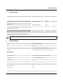
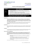
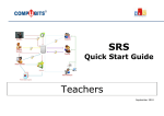
Block diagram
Safe area
E.g., PSM-ME-RS232/RS485-P
A+5V
GND
B+
RS-485
Trans.
8
6
5
3
X2
RS-485
RS-232
PC
24 V
24 V
5V
control
6
data
5V
HART connection board
X1
HART
CH 1...32
FSK
modem
FLK 14 connector
µC
Safety notes
WARNING: Risk of electric shock
Please observe the following notes during installation and operation:
– Observe all national assembly and installation regulations (e.g., EN 60079-14), national safety and accident
prevention regulations, generally recognized technical regulations, as well as the safety notes in the operating
instructions.
– Install the HART multiplexer outside potentially explosive areas.
– Use the module for its intended purpose, i.e., only for its approved application (see page 1).
– Incorrect or improper use or failure to observe the notes in the operating instructions invalidates the warranty.
– Modifications and changes to the module are not permitted.
– The module must only be installed and operated when in an undamaged, dry, and clean state.
103246_en_01
PHOENIX CONTACT
4
MACX MCR-S-MUX
7
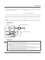
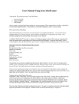
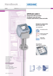
Structure
1
2
3
4
5
6
7
9
1
HA
5V
3
oa
24 V
X2
rd
HA
RT
X1
234
01
ADDRESS
234
01
56
56
01
µC
MACX MCR-S-MUX
CH
16
Seri
al N
o. X
XXX
6
9k
k2
19
k4
38 7k6
5
1
10
6
0
10
789
m
4
5
56
789
FS
K
mo
de
8
9
3
9
CH
FL
.1..
K 1 X1
.32
4C
on
ne
cto
r
5V
RS
4
Tra 85
ns
.
erb
234
5
oth
control
RS485
6
A+5 V
GND
B+
8
24 V
X2
MA
Or CX M
d.- C
N R
ltip o.: 2 -S-M
8 6 UX
lex
HA
5
er
RT
59
M
Mu
data
RT
PC
789
www.interface.phoenixcontact.com
2
FLK connection
D-SUB connection
"PWR" LED, power
"ERR" LED, error
"HART-Tx"/"HART-Rx" LEDs, data transmission
Rotary switch for RS-485 address
Rotary switch for number of channels and transmission
speed
"RS485-Tx"/"RS485-Rx" LEDs
Universal snap-on foot for EN DIN rails
CH
32 A
k2
19 k6
9 k2
19
k4
38
k6
57 A
6
9k
7
8
XXX
X
8
Power supply
The HART multiplexer is supplied with power by the HART
connection board, e.g.,MACX MCR-S-MUX-TB, which is
connected via the 14-pos. flat-ribbon cable.
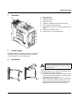
9
Installation
WARNING: Danger if installed incorrectly
C
Install the HART multiplexer outside potentially
explosive areas.
B
D
A
103246_en_01
The assignment of the connection terminal blocks is shown
in the block diagram. The module can be snapped onto all
35 mm DIN rails according to EN 60715.
• Push the module onto the DIN rail from below (A). Push
the module from the front toward the mounting surface
until it engages with a click (B).
• Pull the base latch up using a screwdriver, needle-nose
pliers or similar (C). Pull the top edge of the module
away from the mounting surface and pull the module
diagonally downward away from the DIN rail (D).
PHOENIX CONTACT
5
MACX MCR-S-MUX
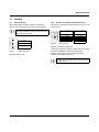
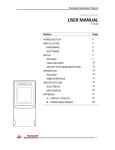
10
Settings
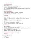
10.1
RS-485 address
Each HART multiplexer that is installed is assigned an
address. This is set directly on the front of the multiplexer.
Please note that the setting is not indicated by the
slot for the screwdriver, but by a small slot on the
edge of the rotary switch.
23
78
1
1
= Units
10
= Tens
100
= Hundreds
901
ADDRESS
23
78
456
10
901
78
456
100
16 CH = 16 channels
16 CH
32 CH
9k6
19k2
19k2 A
9k6
19k2
38k4
57k6
9k6 A
Figure 2
9k6
19k2
38k4
57k6
=
=
=
=
9.6 kbps
19.2 kbps
38.4 kbps
57.6 kbps
32 CH = 32 channels
19k2
9k6
19k2
38k4
57k6
9k6 A
=
=
=
=
=
=
19.2 kbps *)
9.6 kbps
19.2 kbps
38.4 kbps
57.6 kbps
9.6 kbps *)
Rotary switch
Example: 16 channels, 9600 bps
901
Figure 1
Number of channels/transmission speed
The number of channels and transmission speed are set in
the same way.
38k4
57k6
456
23
10.2
Rotary switches
Example: Address 103
*) Select these settings ("19k2 A", "9k6 A") when connecting
the HART multiplexer to PRM (ARCOM protocol).
Select the "9k6" setting when operating the HART
multiplexer with AMS (Version 6.2).
Settings are only applied after a software reset or
module restart.
103246_en_01
PHOENIX CONTACT
6
MACX MCR-S-MUX
11
Startup
12
11.1
Starting the HART multiplexer
LED indicators
•
•
Connect the flat-ribbon cable (supplied as standard
with the module) to the HART connection board, e.g.,
MACX MCR-S-MUX-TB.
Connect the HART connection board, e.g., MACX
MCR-S-MUX-TB, to the 24 V DC supply voltage.
The HART multiplexer scans all 32 channels (default
setting) for connected HART field devices (CMD 0).
11.2
Des.
PWR
Operating states
Color Indicator
Green Steady
light:
HART-Tx Yellow Lit
HART-Rx
alternately:
RS485-Rx Yellow Lit
RS485-Tx
alternately:
Supply voltage present,
operation OK
Communication with
HART field devices OK
Communication with the
PC via the RS-485
interface OK
LED indicators on startup
(See also "Troubleshooting" on page 15)
Des.
PWR
Color Indicator
Green Steady
light:
Flashing:
HART-Tx Yellow Flashing
briefly:
HART-Rx Yellow Flashing
briefly:
ERR
11.3
Red
Flashing
briefly:
Supply voltage present,
operation OK
Module error; switch
module off/on again
Request to field device
Confirmation from field
device; communication
OK
No confirmation from field
device
Communication with field devices
An RS-485 bus is not required for communication
with field devices.
Once scanning is complete, the HART multiplexer
establishes communication with the HART field devices that
are found.
The "HART-Tx" and "HART-Rx" LEDs light up alternately.
If no field devices are found when the HART multiplexer is
started, both LEDs remain off.
If modules are added later, they must be located and added
using the PC software (e.g., in Cornerstone using "Learn" or
"Add instrument").
HART communication is only possible if the control circuit
resistance is between 230 Ω and 600 Ω. An additional
resistor may be required. 250 Ω is sufficient in most cases.
103246_en_01
PHOENIX CONTACT
7
MACX MCR-S-MUX
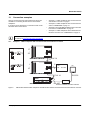
13
Connection examples
Various connection boards and transmission options are
available for connecting the field devices to the HART
multiplexer.
–
"Example 1 - HART multiplexer with connection board
and interface converter" on page 8
"Example 2 - HART multiplexer with connection board
and FL COMSERVER" on page 10
"Example 3 - Several HART multiplexer with connection
board and FL COMSERVER" on page 12
"Example 4 - HART multiplexer with motherboard and
interface converter or FL COMSERVER" on page 13
–
If one board is not sufficient, the connection board can be
extended with a second board.
–
–
For a detailed description of the installation of the HART multiplexer and additional information, please refer to the
user manual at www.phoenixcontact.net/catalog.
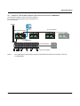
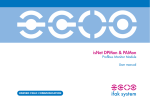
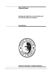
13.1
Example 1 - HART multiplexer with connection board and interface converter
1
17
16
32
...
17
32
FLK 14
MACX MCR-S-MUX-TB
or
17
1
2
1
US1
PC
...
20 ... 30 V DC
16
32
16
MACX MCR-S-MUX-TB
FLK 14
X1
78
78
901
78
901
9
1
10
100
X2
456
MACX MCR-S-MUX
23
456
ADDRESS
23
456
32 CH
38k4
16 CH
19k2 A
9k6
19k2
57k6
9k6 A
9k6
19k2
38k4
57k6
23
901
MACX MCR-S-MUX
RS-232
RS-485
Interface converter, RS-485 to RS-232
Figure 3
103246_en_01
MACX MCR-S-MUX HART multiplexer with MACX MCR-S-MUX-TB connection board and interface converter
PHOENIX CONTACT
8
MACX MCR-S-MUX
The following components are required:
– Field device
HART-capable
Ex-certified, if necessary
– Signal converter
HART-penetrable
Ex-certified, if necessary, for explosion protection
through energy limitation (EX-i) of the circuit for the field
device. For example, a repeater power supply that
supplies the field device and forwards the process
signal (4 ... 20 mA) with electrical isolation to a
controller.
– If required, a suitable terminal block in order to route
the signal to the connection board.
– HART connection board
Here, a maximum of 16 channels are connected per
board. An FLK plug can be used to extend this to
32 channels by adding a board.
– HART multiplexer
Accepts the HART signal, which was previously
decoupled capacitively, and forwards it via an RS-485
interface.
A maximum of 32 field devices in succession can
therefore communicate bidirectionally via a HART
multiplexer.
The flat-ribbon cable for connection to the connection
board is supplied as standard.
– Interface converter, RS-485 to RS-232
– If necessary, a resistor for the signal cable
A termination resistor may be required in the signal
cable. According to the HART specification, a
resistance value of between 230 and 600 Ω is required
for the transmission of the HART signal.
– Power supply
The converter, connection board, signal converter, and,
if necessary, the field device must be supplied with
24 V.
Software
The following may be required:
– Standard software tools, such as Cornerstone, AMS
(Version 6.2 or later), PDM, PRM, FieldCare or
PACTware
– HART OPC server (HCF server - the program can be
purchased from the HCF (HART Communication
Foundation))
103246_en_01
PHOENIX CONTACT
9
MACX MCR-S-MUX
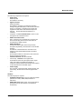
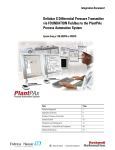
13.2
Example 2 - HART multiplexer with connection board and FL COMSERVER
The HART multiplexer organizes bidirectional data
exchange between a maximum of 32 field devices and a
separate PC or controller.
HART connection boards
4...20 mA
X2
456
1
Ethernet
901
456
78
ADDRESS
23
78
23
X1
10
901
23
456
78
100
32
17
32
1
16
1
16
MACX MCR-S-MUX
901
17
16 CH
32 CH
9k6
19k2
19k2 A
9k6
19k2
38k4
57k6
38k4
57k6
9k6 A
HART multiplexer FL COMSERVER
4.1 4.2
5.1 5.2
4.1 4.2
5.1 5.2
4.1 4.2
5.1 5.2
4.1 4.2
5.1 5.2
4.1 4.2
5.1 5.2
4.1 4.2
5.1 5.2
4.1 4.2
5.1 5.2
4.1 4.2
5.1 5.2
4.1 4.2
5.1 5.2
4.1 4.2
5.1 5.2
4.1 4.2
5.1 5.2
4.1 4.2
5.1 5.2
4.1 4.2
5.1 5.2
1.1 1.2
2.1 2.2
3.1 3.2
PWR
MACX MCR-EX-SL-RPSSI-I
1.1 1.2
2.1 2.2
3.1 3.2
PWR
MACX MCR-EX-SL-RPSSI-I
1.1 1.2
2.1 2.2
3.1 3.2
PWR
MACX MCR-EX-SL-RPSSI-I
1.1 1.2
2.1 2.2
3.1 3.2
PWR
MACX MCR-EX-SL-RPSSI-I
1.1 1.2
2.1 2.2
3.1 3.2
PWR
MACX MCR-EX-SL-RPSSI-I
1.1 1.2
2.1 2.2
3.1 3.2
PWR
MACX MCR-EX-SL-RPSSI-I
1.1 1.2
2.1 2.2
3.1 3.2
PWR
MACX MCR-EX-SL-RPSSI-I
1.1 1.2
2.1 2.2
3.1 3.2
PWR
MACX MCR-EX-SL-RPSSI-I
1.1 1.2
2.1 2.2
3.1 3.2
PWR
MACX MCR-EX-SL-RPSSI-I
1.1 1.2
2.1 2.2
3.1 3.2
PWR
MACX MCR-EX-SL-RPSSI-I
1.1 1.2
2.1 2.2
3.1 3.2
PWR
MACX MCR-EX-SL-RPSSI-I
1.1 1.2
2.1 2.2
3.1 3.2
PWR
MACX MCR-EX-SL-RPSSI-I
PWR
MACX MCR-EX-SL-RPSSI-I
1.1 1.2
2.1 2.2
3.1 3.2
MACX MCR-EX-SL-RPSSI-I
1.1 1.2
2.1 2.2
3.1 3.2
PWR
4.1 4.2
5.1 5.2
32 signal converters
4...20 mA
4
5
2
6
3
1
Figure 4
Temperature transducers
MACX MCR-S-MUX HART multiplexer with MACX MCR-S-MUX-TB connection board and FL COMSERVER
The following components are required:
– Field device
HART-capable
Ex-certified, if necessary
– Signal converter
HART-penetrable
Ex-certified, if necessary, for explosion protection
through energy limitation (EX-i) of the circuit for the field
device. For example, a repeater power supply that
supplies the field device and forwards the process
signal (4 ... 20 mA) with electrical isolation to a
controller.
– If required, a suitable terminal block in order to route
the signal to the connection board.
– HART connection board
Here, a maximum of 16 channels are connected per
board. An FLK plug can be used to extend this to
32 channels by adding a board.
– HART multiplexer
Accepts the HART signal, which was previously
decoupled capacitively, and forwards it via an RS-485
interface.
A maximum of 32 field devices in succession can
therefore communicate bidirectionally via a HART
multiplexer.
The flat-ribbon cable for connection to the connection
board is supplied as standard.
103246_en_01
–
–
–
–
FL COMSERVER
Has an RJ45 interface for the Ethernet connection.
Ethernet cable
If necessary, a resistor for the signal cable
A termination resistor may be required in the signal
cable. According to the HART specification, a
resistance value of between 230 and 600 Ω is required
for the transmission of the HART signal.
Power supply
The converter, connection board, signal converter, and,
if necessary, the field device must be supplied with
24 V.
PHOENIX CONTACT
10
MACX MCR-S-MUX
Software
The following may be required:
– CommPort Redirector (Version 2.2/3 in the example)
The CommPort Redirector program, which is supplied
as standard with the FL COMSERVER, provides a
virtual COM port on the PC, because the HART OPC
server expects a COM interface.
Version 2.2/3 can be used up to Windows XP. Version
4.3 is available for Windows XP or later.
– Browser for configuring the FL COMSERVER
– Standard software tools, such as Cornerstone, AMS
(Version 6.2 or later), PDM, PRM, FieldCare or
PACTware
– HART OPC server (HCF server - the program can be
purchased from the HCF (HART Communication
Foundation))
103246_en_01
PHOENIX CONTACT
11
MACX MCR-S-MUX
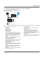
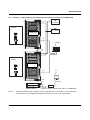
13.3
Example 3 - Several HART multiplexer with connection board and FL COMSERVER
Several HART multiplexer can be connected in parallel so
that, in theory, up to 4000 channels can be visualized on a
PC via the interface.
PLC/IOs
Ethernet
up to 125 modules
MACX MCR-S-MUX
32
17
32
1
16
1
16
32 CH
9k6
19k2
19k2 A
9k6
19k2
38k4
57k6
23
456
ADDRESS
23
1
456
10
456
23
23
17
16 CH
38k4
57k6
9k6 A
17
32
17
32
1
16
1
16
MACX MCR-S-MUX
23
23
901
901
16
MACX MCR-S-MUX
901
23
ADDRESS
23
901
901
23
23
ADDRESS
23
901
MACX MCR-S-MUX
901
32
1
901
17
16
38k4
57k6
9k6 A
78
32
1
19k2 A
9k6
19k2
X2
78
17
32 CH
9k6
19k2
38k4
57k6
100
78
16
16 CH
1
10
456
78
32
1
38k4
57k6
9k6 A
X1
456
456
78
17
16
19k2 A
9k6
19k2
100
78
32
1
32 CH
9k6
19k2
X2
1
10
456
78
78
17
16 CH
38k4
57k6
X1
456
456
78
78
100
78
78
ADDRESS
23
X2
1
10
456
901
X1
456
456
901
X2
100
901
X1
901
HART connection board
16 CH
32 CH
9k6
19k2
19k2 A
9k6
19k2
38k4
57k6
38k4
57k6
9k6 A
HART multiplexer
FL COMSERVER
4...20mA
4.1 4.2
5.1 5.2
4.1 4.2
5.1 5.2
4.1 4.2
5.1 5.2
4.1 4.2
5.1 5.2
4.1 4.2
5.1 5.2
4.1 4.2
5.1 5.2
4.1 4.2
5.1 5.2
4.1 4.2
5.1 5.2
4.1 4.2
5.1 5.2
4.1 4.2
5.1 5.2
4.1 4.2
5.1 5.2
4.1 4.2
5.1 5.2
4.1 4.2
5.1 5.2
4.1 4.2
5.1 5.2
4.1 4.2
5.1 5.2
4.1 4.2
5.1 5.2
4.1 4.2
5.1 5.2
4.1 4.2
5.1 5.2
4.1 4.2
5.1 5.2
4.1 4.2
5.1 5.2
4.1 4.2
5.1 5.2
4.1 4.2
5.1 5.2
4.1 4.2
5.1 5.2
4.1 4.2
5.1 5.2
4.1 4.2
5.1 5.2
4.1 4.2
5.1 5.2
4.1 4.2
5.1 5.2
4.1 4.2
5.1 5.2
4.1 4.2
5.1 5.2
4.1 4.2
5.1 5.2
4.1 4.2
5.1 5.2
4.1 4.2
5.1 5.2
4.1 4.2
5.1 5.2
4.1 4.2
5.1 5.2
4.1 4.2
5.1 5.2
4.1 4.2
5.1 5.2
4.1 4.2
5.1 5.2
4.1 4.2
5.1 5.2
4.1 4.2
5.1 5.2
4.1 4.2
5.1 5.2
4.1 4.2
5.1 5.2
4.1 4.2
5.1 5.2
4.1 4.2
5.1 5.2
4.1 4.2
5.1 5.2
4.1 4.2
5.1 5.2
1.1 1.2
2.1 2.2
3.1 3.2
PWR
4.1 4.2
5.1 5.2
1.1 1.2
2.1 2.2
3.1 3.2
PWR
MACX MCR-EX-SL-RPSSI-I
1.1 1.2
2.1 2.2
3.1 3.2
PWR
MACX MCR-EX-SL-RPSSI-I
1.1 1.2
2.1 2.2
3.1 3.2
PWR
MACX MCR-EX-SL-RPSSI-I
1.1 1.2
2.1 2.2
3.1 3.2
PWR
MACX MCR-EX-SL-RPSSI-I
1.1 1.2
2.1 2.2
3.1 3.2
PWR
MACX MCR-EX-SL-RPSSI-I
1.1 1.2
2.1 2.2
3.1 3.2
PWR
MACX MCR-EX-SL-RPSSI-I
1.1 1.2
2.1 2.2
3.1 3.2
PWR
MACX MCR-EX-SL-RPSSI-I
up to 4000 signals
MACX MCR-EX-SL-RPSSI-I
1.1 1.2
2.1 2.2
3.1 3.2
PWR
MACX MCR-EX-SL-RPSSI-I
1.1 1.2
2.1 2.2
3.1 3.2
PWR
MACX MCR-EX-SL-RPSSI-I
1.1 1.2
2.1 2.2
3.1 3.2
PWR
MACX MCR-EX-SL-RPSSI-I
1.1 1.2
2.1 2.2
3.1 3.2
PWR
MACX MCR-EX-SL-RPSSI-I
1.1 1.2
2.1 2.2
3.1 3.2
PWR
MACX MCR-EX-SL-RPSSI-I
1.1 1.2
2.1 2.2
3.1 3.2
PWR
MACX MCR-EX-SL-RPSSI-I
1.1 1.2
2.1 2.2
3.1 3.2
PWR
MACX MCR-EX-SL-RPSSI-I
1.1 1.2
2.1 2.2
3.1 3.2
PWR
MACX MCR-EX-SL-RPSSI-I
1.1 1.2
2.1 2.2
3.1 3.2
PWR
MACX MCR-EX-SL-RPSSI-I
1.1 1.2
2.1 2.2
3.1 3.2
PWR
MACX MCR-EX-SL-RPSSI-I
1.1 1.2
2.1 2.2
3.1 3.2
PWR
MACX MCR-EX-SL-RPSSI-I
1.1 1.2
2.1 2.2
3.1 3.2
PWR
MACX MCR-EX-SL-RPSSI-I
1.1 1.2
2.1 2.2
3.1 3.2
PWR
MACX MCR-EX-SL-RPSSI-I
1.1 1.2
2.1 2.2
3.1 3.2
PWR
MACX MCR-EX-SL-RPSSI-I
1.1 1.2
2.1 2.2
3.1 3.2
PWR
MACX MCR-EX-SL-RPSSI-I
1.1 1.2
2.1 2.2
3.1 3.2
PWR
MACX MCR-EX-SL-RPSSI-I
1.1 1.2
2.1 2.2
3.1 3.2
PWR
MACX MCR-EX-SL-RPSSI-I
1.1 1.2
2.1 2.2
3.1 3.2
PWR
MACX MCR-EX-SL-RPSSI-I
1.1 1.2
2.1 2.2
3.1 3.2
PWR
MACX MCR-EX-SL-RPSSI-I
1.1 1.2
2.1 2.2
3.1 3.2
PWR
MACX MCR-EX-SL-RPSSI-I
1.1 1.2
2.1 2.2
3.1 3.2
PWR
MACX MCR-EX-SL-RPSSI-I
1.1 1.2
2.1 2.2
3.1 3.2
PWR
MACX MCR-EX-SL-RPSSI-I
1.1 1.2
2.1 2.2
3.1 3.2
PWR
MACX MCR-EX-SL-RPSSI-I
1.1 1.2
2.1 2.2
3.1 3.2
PWR
MACX MCR-EX-SL-RPSSI-I
1.1 1.2
2.1 2.2
3.1 3.2
PWR
MACX MCR-EX-SL-RPSSI-I
1.1 1.2
2.1 2.2
3.1 3.2
PWR
MACX MCR-EX-SL-RPSSI-I
1.1 1.2
2.1 2.2
3.1 3.2
PWR
MACX MCR-EX-SL-RPSSI-I
1.1 1.2
2.1 2.2
3.1 3.2
PWR
MACX MCR-EX-SL-RPSSI-I
1.1 1.2
2.1 2.2
3.1 3.2
PWR
MACX MCR-EX-SL-RPSSI-I
1.1 1.2
2.1 2.2
3.1 3.2
PWR
MACX MCR-EX-SL-RPSSI-I
1.1 1.2
2.1 2.2
3.1 3.2
PWR
MACX MCR-EX-SL-RPSSI-I
1.1 1.2
2.1 2.2
3.1 3.2
PWR
MACX MCR-EX-SL-RPSSI-I
1.1 1.2
2.1 2.2
3.1 3.2
PWR
MACX MCR-EX-SL-RPSSI-I
1.1 1.2
2.1 2.2
3.1 3.2
PWR
MACX MCR-EX-SL-RPSSI-I
1.1 1.2
2.1 2.2
3.1 3.2
PWR
MACX MCR-EX-SL-RPSSI-I
1.1 1.2
2.1 2.2
3.1 3.2
PWR
MACX MCR-EX-SL-RPSSI-I
1.1 1.2
2.1 2.2
3.1 3.2
PWR
MACX MCR-EX-SL-RPSSI-I
1.1 1.2
2.1 2.2
3.1 3.2
PWR
MACX MCR-EX-SL-RPSSI-I
MACX MCR-EX-SL-RPSSI-I
1.1 1.2
2.1 2.2
3.1 3.2
PWR
4.1 4.2
5.1 5.2
up to 4000 signals
Figure 5
103246_en_01
Several MACX MCR-S-MUX HART multiplexer with MACX MCR-S-MUX-TB connection board and
FL COMSERVER
PHOENIX CONTACT
12
MACX MCR-S-MUX
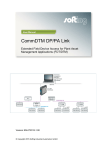
13.4
Example 4 - HART multiplexer with motherboard and interface converter or FL COMSERVER
2
1
UB1
...
20 ... 30 V DC
Ex area
2
UB2
20 ... 30 V DC
Motherboard 2
or
37
Controller
16
FLK
14
1
...
Ex area
Motherboard 1
or
37
PC
16
FLK
14
X1
901
78
78
901
78
103246_en_01
RS-232
9
1
10
100
HART multiplexer
Figure 6
X2
456
23
456
ADDRESS
23
456
19k2 A
9k6
19k2
32 CH
38k4
57k6
9k6 A
9k6
19k2
38k4
57k6
16 CH
23
901
MACX MCR-S-MUX
RS-485
Interface converter, RS-485 to RS-232 or FL COMSERVER
MACX MCR-S-MUX HART multiplexer with two PI-EX-MB-S/16-01-2/D-SUB (2 x 16 channels) HART
connection boards and PSM-ME-RS232/RS485-P interface converter or FL COMSERVER
PHOENIX CONTACT
13
MACX MCR-S-MUX
The following components are required:
– Field device
HART-capable
Ex-certified, if necessary
– Signal converter
HART-penetrable
Ex-certified, if necessary, for explosion protection
through energy limitation (EX-i) of the circuit for the field
device. For example, a repeater power supply that
supplies the field device and forwards the process
signal (4 ... 20 mA) with electrical isolation to a
controller.
– If required, a suitable terminal block in order to route
the signal to the connection board.
– HART connection board, PI-EX-MB-S/16-01-2/DSUB
Here, a maximum of 16 channels are connected per
board. An FLK plug can be used to extend this to 32
channels by adding a board.
– HART multiplexer
Accepts the HART signal, which was previously
decoupled capacitively, and forwards it via an RS-485
interface.
A maximum of 32 field devices in succession can
therefore communicate bidirectionally via a HART
multiplexer.
The flat-ribbon cable for connection to the connection
board is supplied as standard.
– Interface converter, RS-485 to RS-232 or
FL COMSERVER
– Ethernet cable (for FL COMSERVER only)
– If necessary, a resistor for the signal cable
A termination resistor may be required in the signal
cable. According to the HART specification, a
resistance value of between 230 and 600 Ω is required
for the transmission of the HART signal.
– Power supply
The converter, connection board, signal converter, and,
if necessary, the field device must be supplied with
24 V.
– Software, see "Software" on page 11
103246_en_01
PHOENIX CONTACT
14
MACX MCR-S-MUX
14
Repair and maintenance
We recommend that you only allow us to repair our modules. In exceptional cases, repairs can also be made by another
approved body.
The modules are maintenance free.
Troubleshooting
Error detection
"PWR" LED off
Possible error cause
Error removal
Auxiliary voltage failure or module fuse faulty Check auxiliary voltage supply.
"PWR" LED flashing
Internal module error
"ERR" LED flashes briefly
No HART field device found
"HART" LEDs off
No HART field device found
"RS485" LEDs off
No RS-485 bus connected.
RS-485 interface not active.
If fuse is faulty, return the module for repair.
Switch module off/on. If LED keeps flashing,
return the module for repair.
Connect HART field device and check
connection.
Connect HART field device and check
connection.
Connect RS-485 interface and check
connection.
If the approaches described prove unsuccessful, please contact our nearest sales center. For a quick response, make sure
you have the following information to hand:
– Type and serial number
– Purchase data
– Error description
– Application (especially input/output circuit)
103246_en_01
PHOENIX CONTACT GmbH & Co. KG • 32823 Blomberg • Germany • Phone: + 49 5235 3-00
www.phoenixcontact.com
15