1
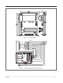
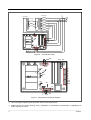
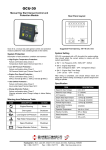
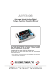
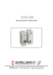
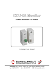
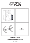
EA448
Generator Automatic Voltage Regulator
Operation Manual
Permanent Magnet Generator or A.R.E.P or Auxiliary Winding Type
Compatible with Leroy Somer R448*
* Use for reference purpose only and not a genuine Leroy Somer product.
Headquarters : No.3, Lane 201, Chien Fu ST., Chyan Jenn Dist., Kaohsiung, TAIWAN
Tel : + 886-7-8121771
Fax : + 886-7-8121775
URL : http://www.kutai.com.tw
1. SPECIFICATION
Sensing Input
Terminal
Frequency
Power Input
Voltage
Output
Voltage
Current
0 ~ 110V = 95 ~ 140V
0 ~ 220V = 170 ~ 260V
0 ~ 380V = 340 ~ 520V
50 / 60 Hz, selectable
40 ~ 150 VAC, 3 phase
Max 160VDC @120VAC
Max 10 A
Voltage Regulation
< ± 0.5% ( with 4% engine governing )
Voltage Build-up
Residual voltage at AVR terminal > 5 VAC
External Volts Adjustment
±10% @ 1K ohm
Response Time
0.3 ~ 1sec @ ±20% Voltage Vibration
Current Droop
2 sec. Max 7% @ P.F. = 0.7
Auxiliary Winding
6~150VAC (No load rms)
LAM Voltage Drop Rate
4.5~6.5V/Hz @ 220VAC
selectable
Dimensions
203mm L * 153mm W * 60.5mm H
Weight
950g ± 2%
2. OPERATION PROCEDURE
3. P3:Stability.
2.1 Jumper Adjustment
4. P4:Under-speed (U/F) and LAM protection: for
knee frequency adjustable us P4.
1. ST1 : Connected wire ST1 for Single phase
measurement. Cut wire ST1 for three phase
measurement.
5. P5:Excitation over current adjustment use P5:
3.5A ~ 10A.
2. ST2 : Response Time : Fast (disconnected) /
Slow(Connected) Select.
2.3 Wiring
PS:It should do stable adjustment with P3.
1. X1-X2:Excitation power auxiliary winding input,
single phase 2 wires.
3. ST3:For 50/60Hz selection use Jumper.ST3.
2. Z1-Z2:Harmonic Power input (Multi-Harmonic).
4. ST4 : Remove wire ST4 to Connect external
potentiometer (1KΩ). Connect wire ST4 when it is
not necessary to connect external potentiometer.
3. E+:Positive Output Terminal for Excitation power.
5. ST6:Instantaneous Compensation for Voltage.
PS:Remove wire ST6 when the regulator is used
in higher 600KVA.
6. ST7:Jumpers connected.
7. J1:Connected with LAM protection. Discounted
without LAM protection. No LAM protection, for
knee frequency adjustment use P4.
8. J2:LAM voltage drop rate, 1-2 about 4.5V/Hz,
2-3 about 6.5V/Hz @ 220VAC.
2.2 Adjustment
1. P1:Adjustment of quadrature droop. (Max 7%).
4. E-:Negative Output Terminal for Excitation power.
5. 0 ~ 110:Measure Power Input 110VAC.
6. 0 ~ 220:Measure Power Input 220VAC.
7. 0 ~ 380:Measure Power Input 380VAC.
Note:
:
1. When excitation power is three phase input,
connect X2, X1, Z2. See Figure 3.
2. Fuse capacity:10A / 250V.
3. When the regulator works normal, the LED will keep
“Light” condition. The LED will be turned off when
Stand-by power works in normal usual. In this
condition, the rated voltage will decrease
automatically and the voltage adjustment will failure
2. P2:Output Voltage adjustment by using P2.
______________________________________________________________________________________
2
EA448
VOLT
STAB
V/HZ
EXC. MAX
STAT
Figure 1 Outline Drawing
C.T
N:1A
Stator wires
Exciter field
Armature
R
S
T
FU
FV
FW
S2
S1
S4
S3
Fuse 10A
50HZ
60HZ
AVR EA448
X2
Z1
X1
Z2
E+
E0V
110V
220V
380V
S2
S1
3ph in
EXT.VR 1k Ohm
Figure 2
Power and Wiring for Harmonic Power
______________________________________________________________________________________
EA448
3
C.T
N:1A
Stator wires
Exciter field
Armature
R
S
T
FU
FV
FW
S2
S1
S4
S3
Fuse 10A
50HZ
60HZ
AVR EA448
X2
Z1
X1
Z2
E+
E0V
110V
220V
380V
S2
S1
3ph in
EXT.VR 1k Ohm
Figure 3 Three phase wiring
ST3
Fuse 10A
50HZ
60HZ
P5
J1
12 3
LED
X2
Z1
X1
Z2
E+
E0V
110V
220V
380V
J2
P4
ST2
P3
ST6
ST7
P2
ST1
P1
S2
S1
VR
1k
3ph in
Figure 4
ST4
Adjustment and Jumper Diagram
※ Use only original supplied spare protection fuse for fuse replacement.
※ Please accept our sincere apology if any modification in performance, specification or appearance is
made without prior notice.
______________________________________________________________________________________
4
EA448