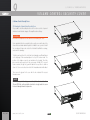
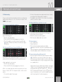
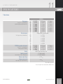
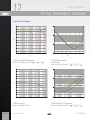
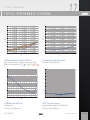
1
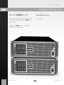
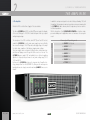
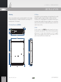
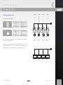
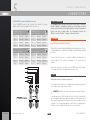
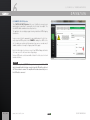
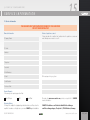
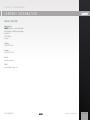
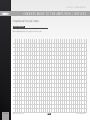
Q Q - P O W E R 14 POWER AMPLIFIER USER MANUAL MADE IN GERMANY Q - P O W E R 14 | POWER AMPLIFIER CONTENTS Welcome to the Q-POWER 14 User Manual4 7. Protections21 11. Specifications27 Important Safety Instructions5 7.1 Power Amp Protection Systems21 12. Typical Performance Diagrams30 Explanation of Symbols7 7.1.1 Clip Limiter21 12.1 Gain vs. frequency, 120 W output power30 EC Declaration of Conformity8 7.1.2 SOA Protection21 12.2 Phase vs. frequency30 FCC Compliance Notice8 7.1.3 DC Protection21 12.3 THD @ 1 kHz vs. input level30 1. Welcome to CAMCO9 7.1.4 DC Servo21 12.4 THD vs. frequency, 120 W output power30 1.1 Unpacking9 7.1.5 Output Current Limiter21 12.5 Channel separation vs. frequency @ 3 × 120 W / 4 Ω31 2. The Amplifier10 7.1.6 Underimpedance Limiter21 12.6 DIM100 vs. input level @ 4 Ω load31 2.1 The Q-POWER 14 Front11 7.1.7 Output Short Circuit Protection21 12.7 Common mode rejection ratio vs. frequency31 2.2 The Q-POWER 14 Rear11 7.1.8 Thermal Limitation and Protection21 12.8 FFT of noise level vs. frequency31 3. Mains12 7.1.9 High Frequency Protection22 12.9 Output impedance vs. frequency32 3.1 Mains Supply12 7.2 Mains and Power Supply Protections22 12.10 Damping factor vs. frequency32 3.2 Mains Plugs and Cables12 7.2.1 Inrush Current Limitation 22 13. Unit Conversion Equations and Lookup Table33 3.3 On / Off Switch12 7.2.2 Mains Overvoltage Detection22 13.1 Unit Conversion Equations33 3.4 Mains Voltage Range13 7.2.3 Mains Surge Overvoltage Protection 22 13.2 Lookup Table33 3.5 Inrush Current Limitation13 7.2.4 Mains Failure Detection22 14. Warranty Information34 3.6 Mains Power Consumption and Current Draw14 7.2.5 Mains Overcurrent Limiter22 14.1 Summary of Warranty34 3.7 FuseProtect™ Limiter - Mains Circuit Breaker selection15 7.2.6 Over Current Protection22 14.2 Items Excluded from This Warranty34 4. Mounting16 7.2.7 Fuse / MCB Protection (FuseProtect™ Limiter) 22 14.3 What CAMCO Will Do34 4.1 Mounting Dimensions Q-POWER 1416 7.2.8 Thermal Protection22 14.4 How to Obtain Warranty Service34 4.2 Cooling16 8. Filter Cleaning23 14.5 CAMCO Product Improvement34 4.3 Fans16 8.1 Removing the Filter System and Cleaning 23 15. Service Information35 5. Input and Output Connectors17 9. Volume Control Security Cover24 16. Maintenance Information 36 5.1 Analogue Input Connectors17 9.1 Mounting the Volume Control Security Cover24 17. Decommissioning36 18 10. Troubleshooting25 Company information37 6. Operation19 10.1 No reaction when switching the amplifier on25 Changes Made to The Amplifier / Notices38 6.1 Indicators19 10.2 All four signal LEDs are red, the green On-LEDs are off25 Hole template for Volume Control Security Cover40 6.1.1 ON LEDs19 10.3 All green On-LEDs are on, but there is no sound25 6.1.2 SIGNAL/Protect LEDs (multifunctional)19 10.4 Sound is distorted25 19 10.5 Sound is distorted although Clip Limiter is On25 ® 5.2 SPEAKON Loudspeaker Output Connectors 6.1.3 I-OUT Output Current LEDs 6.1.4 CLIP LEDs (multifunctional)19 10.6 Signal and Clip LED of one or more channels are red 6.2 Controls19 intermittently26 6.2.1 Volume Control19 10.7 Output power lower than usual26 6.2.2 Gain Selector19 10.8 The amplifier gets hot very quickly26 6.2.3 Clip Limiter Switch19 10.9 The CAMCO USB MCB Updater application does not 6.3 CAMCO USB MCB Updater20 USER MANUAL connect to the amplifier26 www.camcoaudio.com 3 / 42 Q - P O W E R 14 | POWER AMPLIFIER INFORMATION FOR USE Welcome to the Q-POWER 14 User Manual TDA282USEREND_User_Manual_Q14 Please visit our website www.camcoaudio.com for the latest version of this user manual. Please note that the leading version of CAMCO manuals is always the English one. Revision D, 2015-05-22 © Copyright 2015 by CAMCO Produktions- und Vertriebs-GmbH für Beschallungs- und Beleuchtungsanlagen 4 / 42 www.camcoaudio.com USER MANUAL Q - P O W E R 14 | POWER AMPLIFIER IMPORTANT SAFETY INSTRUCTIONS Important Safety Instructions 1. General The amplifier may only be used in accordance with the information provided in the user manual. Before and during the usage of the amplifier please ensure that all recommendations, especially the safety recommendations as detailed in the user manual, are adhered to. The Q-POWER 14 amplifier is designed for the amplification of pulsed audio signals. The amplifier should only be connected to speakers with an average impedance as indicated. 2. User Manual Read the information for use (user manual) and heed all warnings. Keep this user manual in a safe place during the lifetime of the amplifier. The user manual forms an integral part of the amplifier. Reselling the amplifier is only possible if the user manual is available. In case of reselling the amplifier, the reseller has to document any changes made to the amplifier in writing and pass the documentation on to the buyer. 3. Environments Use this amplifier only in E1, E2, E3, E4 or E5 environments according to EN55103-2 “Electromagnetic compatibility – Product family standard for audio, video, and audio-visual and entertainment lighting control apparatus for professional use – Part 2: Immunity”. 4. Mounting / Placement Do not place this amplifier on an unstable cart, stand, tripod, bracket, or table. The amplifier may fall causing serious injury and serious damage to the product. Any mounting of the amplifier should follow the manufacturer´s instructions. Only mounting accessory shall be used which is recommended by the manufacturer. USER MANUAL 5. Mains Connection The amplifier may only be connected to a socket with a protective earth connector. 6. Power Cord Protection Power supply cords should be routed so that they are not likely to be walked on or pinched by items placed upon them or against them, paying particular attention to cords and plugs and the point where they exit from the amplifier. The disconnection device from mains (mains plug or external all-pole circuit breaker) shall remain readily operable and freely accessible at all times. 7. Heat Do not use this amplifier near any heat sources such as radiators, heat registers, stoves, or other apparatuses that produce heat. 8. Water and Moisture Do not expose this device to rain, moisture, dripping or splashing water. Do not use this amplifier near water (for example swimming pools and fountains). Do not place any objects containing liquids, such as bottles or glasses, on the top of the unit. Do not splash liquids on the unit. IP-20 equipment. There is no protection against splashing water. 9. Ventilation Slots and openings in the cabinet are provided for ventilation to ensure reliable operation of the amplifier and to protect it from overheating. These openings must not be blocked or covered. This amplifier should not be installed unless proper ventilation is provided or manufacturer’s instructions have been adhered to. 10. Interference of External Objects and/or Liquids with the Appliance Never push objects of any kind into this amplifier through openings as they may touch dangerous voltage points or short-out parts that could result in fire or electric shock. Never spill liquid of any kind on the amplifier. www.camcoaudio.com 5 / 42 Q - P O W E R 14 | POWER AMPLIFIER IMPORTANT SAFETY INSTRUCTIONS 11. Connections When you connect the amplifier to other equipment, turn off the power and unplug all of the equipment from the supply source. Failure to do so may cause an electric shock and serious personal injury. Read the user manual of the other equipment carefully and follow the instructions when making the connections. 15. Spare parts When spare parts are required, please ensure that the dealer / distributor only uses spare parts specified by the manufacturer. The use of unauthorized spare parts may result in injury and / or damage through fire or electric shock or other electricity-related hazards. 12. Lightning For additional protection of this amplifier during lightning storms or when it is left unattended and/or unused for long periods of time, unplug it from the wall outlet. This will prevent damage to the amplifier due to lightning and power line surges. Disconnection from the mains power supply can only be achieved by removing the plug from the mains socket or by external disconnecting all poles from the mains. 16. Safety check Upon completion of any service or repairs to this product, ask the dealer / distributor to perform safety checks to determine that the amplifier works properly. Recommendations on how to carry out the safety test can be found in DIN VDE 0701-1 “Maintenance, Modification and Test of Electronic Appliances“. 13. Damages that require service Unplug this amplifier from the mains supply and refer to your dealer / distributor or other authorized repair workshop if any of the following situations occur: > if liquid has been spilled or objects have fallen into the amplifier > if the amplifier has been exposed to rain or moisture > if the amplifier has been dropped or damaged in any other way > if the power supply cord or plug has been damaged > when the amplifier exhibits a distinct change from its normal function or performance > in case the amplifier has been used in a dusty environment for quite a period of time 17. Cleaning Unplug this amplifier from the wall outlet before cleaning. Do not use liquid or aerosol cleaners. Clean only with dry cloth. 18. Packaging and shipping When shipping the Q-POWER 14 amplifier, always use the original shipping carton and packing materials. For maximum protection repack the unit as it was originally packed at the factory. 19. Altitude (for China) The amplifier shall only be operated at altitudes below or equal 2000 m. 14. Servicing All service and repair work must be carried out by a dealer / distributor authorized by CAMCO. Do not attempt to service this amplifier yourself. As opening or removing covers may expose you to dangerous voltage or other hazards, the amplifier may only be opened by qualified personnel. Please refer to your dealer / distributor. 6 / 42 www.camcoaudio.com USER MANUAL Q - P O W E R 14 | POWER AMPLIFIER EXPLANATION OF SYSMBOLS Explanation of Symbols CAUTION RISK OF ELECTRIC SHOCK DO NOT OPEN CAUTION – HIGH VOLTAGE HAZARDS EXIST WITHIN THIS PRODUCT. REFER ALL SERVICING TO AUTHORIZED PERSONNEL. THE LIGHTNING FLASH WITH ARROW HEAD SYMBOL IS INTENDED TO ALERT THE USER TO THE PRESENCE OF UNINSULATED DANGEROUS VOLTAGE WITHIN THE PRODUCT’S ENCLOSURE. THE EXCLAMATION MARK IS INTENDED TO ALERT THE USER TO IMPORTANT INSTRUCTIONS ALSO FOR MAINTENANCE IN THE LITERATURE ACCOMPANYING THE AMPLIFIER. THE LIGHTNING FLASH WITH ARROW HEAD SYMBOL ALERTS THE USER TO DANGEROUSLY HIGH VOLTAGE AT THE OUTPUT CONNECTORS! THAT COULD POTENTIALLY BE LIFE THREATENING. CAUTION – RISK OF ELECTRIC SHOCK – DO NOT OPEN. WARNING – TO PREVENT FIRE OR SHOCK HAZARD, DO NOT EXPOSE THIS AMPLIFIER TO RAIN OR MOISTURE. THE AMPLIFIER SHALL ONLY BE OPERATED AT ALTITUDES BELOW OR EQUAL 2000 M. THE AMPLIFIER MAY ONLY BE CONNECTED TO A SOCKET WITH A PROTECTIVE EARTH CONDUCTOR. USER MANUAL www.camcoaudio.com 7 / 42 Q - P O W E R 14 | POWER AMPLIFIER EC DECLARATION OF CONFIRMITY / FCC COMPLIANCE EC Declaration of Conformity FCC Compliance Notice EC Declaration of Conformity in accordance to EC Directives: Electromagnetic compatibility (Council Directive 2014/30/EC) Low-voltage electrical equipment (Council Directive 2014/35/EC) This device complies with part 15 of the FCC rules. Operation is subject to the following two conditions: > This device may not cause harmful interference, and > this device must accept any interference received, including interference that may cause undesired operation. Manufacturer´s Name: CAMCO Produktions- und Vertriebs-GmbH für Beschallungs- und Beleuchtungsanlagen Manufacturer´s Address: Fischpicke 5, D-57482 Wenden, Germany Declares that the product with the model name: CAMCO Power amplifier Q-POWER 14 Conforms to the following standards: > IEC / EN / UL / CSA 60065 Safety > EN55103-1 Emission (for all environments E1/residential to E5/industrial) > EN55103-2 Immunity (for all environments E1/residential to E5/industrial) > FCC Part 15 Emission (Class B) The operating conditions and application environments presupposed in the information for use (user manual) are to be kept accordingly. This equipment has been tested and found to comply with the limits for a Class B digital device, pursuant to part 15 of the FCC Rules. These limits are designed to provide reasonable protection against harmful interference in a residential installation. This equipment generates, uses, and can radiate radio frequency energy and, if not installed and used in accordance with the instruction manual, may cause harmful interference to radio communications. However, there is no guarantee that interference will not occur in a particular installation. If this equipment does cause harmful interference to radio or television reception, which can be determined by turning the equipment off and on, the user is encouraged to try to correct the interference by one or more of the following measures: Reorient or relocate the receiving antenna. Increase the separation between the equipment and receiver. Connect the equipment into an outlet on a circuit different from that to which the receiver is connected. Consult the dealer or an experienced radio / TV technician for help. Changes or modifications not expressly approved by the party responsible for compliance could void the user’s authority to operate the equipment. Wenden, 18.05.2015 Joachim Stöcker 8 / 42 www.camcoaudio.com USER MANUAL Q - P O W E R 14 | 1 POWER AMPLIFIER WELCOME! 1. Welcome to CAMCO Thank you for choosing CAMCO products. You are now the proud owner of a very advanced CAMCO Amplifier. The technologies used in your amplifier are of the latest generation and designs delivering a far reaching set of results across all functions. 1.1 Unpacking Please unpack and inspect your new amplifier for any damage that may have occurred during transit. If damage is found, notify the transportation company immediately. Only you the consignee may initiate a claim for shipping damage. CAMCO will be happy to cooperate fully as needed. Please save the shipping carton as evidence of damage for the shipper’s inspection. The amplifier has been designed to be incorporated into a professional speaker system and is suitable for use across all applications from Touring Live Sound to Fixed Installations. Even if the amplifier has arrived in perfect condition, save all packing materials so you will have them if you ever need to transport the unit. Your speaker systems will benefit from the renowned CAMCO sonic quality as well as the many operating functions and features detailed within this manual which are incorporated within the design to maximise results. l NOTE Never ship the amplifier without the original packing materials. The CAMCO peace of mind long term manufactures warranty is our commitment to you that every CAMCO amplifier is ready to give you many years of faultless service. When shipping the Q-POWER 14 amplifier, always use the original shipping carton and packing materials. For maximum protection, repack the unit as it was originally packed at the factory. WELCOME TO CAMCO! USER MANUAL www.camcoaudio.com 9 / 42 2 World’s first DSP controlled Power Supply in Professional Audio. The all new Q-POWER 14 with DSP controlled PFC power supply is the flagship of the series, offering up to 14 000 W of undistorted power in an very compact and lightweight package. The development of a DSP controlled, active PFC (Power Factor Correction) enables the Q-POWER 14 to use the mains power supply much more efficiently than conventional designs. The PFC provides solid supply voltage to the amplifier output stages, regardless of fluctuating or dropping mains voltages. The power supply can be configured to different mains circuit breaker characteristics and tripping currents through the USB connector on the rear. The Q-POWER 14 power supply’s DSP automatically choses the best regulating algorithms for highest power performance for any mains voltage range (100 V, 120 V and 230 V). Furthermore the Q-POWER 14 introduces the improved class D amplifier technology already known from the Q-POWER 10, offering smooth and responsive handling with massive output power while maintaining CAMCO’s famous sonic integrity. 10 / 42 www.camcoaudio.com | POWER AMPLIFIER THE AMPLIFIER In addition to an improved signal to noise-ratio offering outstanding 118,5 dB (A-weighted), the impedance headroom has also been increased, meaning that the Q-POWER 14 is able to drive any kind of loudspeaker system even down to the lowest impedances. With the introduction of the Q-POWER SERIES CAMCO aim to deliver simple, pure and reliable power for applications where cost and ease of use are paramount. Power output @ operating mode 4× 3 520 W @ 3,2 Ω peak Q-POWER 14 2. The Amplifier Q - P O W E R 14 4× 3 250 W @ 2,7 Ω 4× 3 030 W @ 3,2 Ω 4× 2 900 W @ 2 Ω 4× 2 520 W @ 4 Ω 4× 1 380 W @ 8 Ω 4× 715 W @ 16 Ω USER MANUAL Q - P O W E R 14 | 2 POWER AMPLIFIER THE AMPLIFIER 2.1 The Q-POWER 14 Front Clip-LEDs I-Out-LEDs Signal-LEDs On-LEDs Volume controls channel A to D Removable air filter system Cooling air inlet vents On/Off switch Optional volume control security cover USER MANUAL 2.2 The Q-POWER 14 Rear Rating plate (placed on the inside of the flap) AC power socket Cooling air outlet vents SPEAKON® output connectors channel A to D USB type B socket (for update and MCB programming only) Interface connector for CAMCO mini-maps Gain selector Clip limiter switch for channel A/B and C/D XLR input connectors channel A to D Euroblock input connectors channel A to D www.camcoaudio.com 11 / 42 3 Q - P O W E R 14 | POWER AMPLIFIER M A I N S S U P P LY 3. Mains 3.1 Mains Supply The Q-POWER 14’s power supply is a true wide-range SMPS with active power factor correction (PFC). This means that it can be operated anywhere in the world without the need of any manual voltage range setting. When mounting or connecting the amp always disconnect it from mains. Only connect the Q-POWER 14 amplifier to an appropriate AC circuit, according to the requirements indicated in the second line on the rating plate. Q-POWER 14 100 - 240 V ~ 50/60 Hz 2200 W 3000 W / 2,7 Ohm And of course do never remove the protective earth conductor, under any circumstances. The Q-POWER 14 must always be connected to a socket with a protective earth connector. ! WARNING DO NEVER REMOVE OR DISCONNECT THE MAINS GROUND/EARTH CONNECTION. IT IS ILLEGAL AND DANGEROUS! 3.3 On / Off Switch The On / Off Switch is a rocker-type switch. It is located on the right side of the front panel. To turn the amplifier on, press on the upper part of the switch. During power up the Clip- and Signal-LEDs of all channels will light up in red for a few seconds. To turn the amplifier off, press on the lower part of the switch. 3.2 Mains Plugs and Cables Only use mains cables with original Neutrik® powerCON® 32 A connectors for safety reasons. l NOTE Please never unplug the powerCON® cable from the amplifier while it is still carrying live voltage. Even if the amplifier is switched off! Unplugging must always be done on the other end of the mains cable (i.e. with the wall outlet plug*, or by the installation circuit breaker(s)). The reason ist that the powerCON® connector is not designed for disconnecting live voltages, as this might deteriorate it’s contact performance over time. * provided the connector is suited as a disconnect device, as for example the “Schuko” plug used in Europe or the Twist-Lock plugs used in North America l NOTE Please make sure to always use appropriate mains cables and wall outlet plugs offering sufficient current rating. à 12 / 42 Amplifier is switched on Amplifier is switched off l NOTE This switch does NOT disconnect the amplifier from mains. Disconnecting the amplifier from the mains can only be achieved by disconnecting the mains plug or by the installation circuit breaker(s). The mains plug or circuit breaker(s) therefore have to be freely accessible at all times. Disconnect the mains plug from the mains during a thunderstorm or when the amplifier remains unused or unsupervised for a prolonged period of time. While switched off and still connected to mains, the Q-POWER 14 will have an average power consumtion of less than 2 W. See also chapter 3.7 for more details on current rating and circuit breaker selection. www.camcoaudio.com USER MANUAL Q - P O W E R 14 | 3 POWER AMPLIFIER M A I N S S U P P LY 3.4 Mains Voltage Range To guarantee the best amplifier performance all over the world the power supply internally works with three mains voltage “grids” or “ranges”. These are: > 100 VAC(Japan) > 110-127 VAC (North and parts of South America) > 200-240 VAC (Europe and the “Rest of the World”) For each grid there is a set of highly optimised control parameters to get the maximum power performance achievable. The appropriate grid is automatically selected each time the amplifier is powered up. The grid selection is done solely inside the power supply’s DSP software, there are no electrical or electromechanical switches (e.g. relays) inside the power supply. The selection of the three grids is based on the analysis of the mains voltage for approx. 1 second, and done on following thresholds: Japan (100 VAC) ß 80 V America (110 – 127 VAC) ROW (Rest of the World) (200 – 240 VAC) 107 V à ß 107 V 140 V à ß 140 V On the other hand, if the Q-POWER 14 is once running in ROW range, the range is never changed anymore, until power loss or manual switch-off. 3.5 Inrush Current Limitation The Q-POWER 14 has a special algorithm dedicated to limit the mains inrush current. This limiter will take action anytime the main SMPS is powered up. It will confine the mains current to a value smaller than 15 ARMS*. * maximum rms value of inrush current over one half-cycle of the mains voltage according to DIN EN 55103-1. l NOTE When demanding very high output powers the mains current can reach levels up to 75 A (ROW range) or 106 A (America and Japan range) for very short periods of time. This could cause lamps to flicker if connected to the same mains as the amplifier. 265 V à l NOTE The power supply will not start below approx. 80 V and above approx. 265 V. Once running, it can handle mains voltages from 50 to 280 V. Once the Q-POWER 14 is powered up the range will be kept even if the mains voltage varies in large borders, according to these thresholds: Range Nominal voltage Operating range Japan 100 VAC 50 V – 180 V America 110 – 127 VAC 50 V – 180 V ROW (Rest of the World) 200 – 240 VAC 50 V – 280 V This means that if the mains voltage rises higher than 180 V in either the Japan or the America range, the power supply will switch off shortly and restart in the ROW range (provided the mains voltage is stable and higher than 140 V). USER MANUAL www.camcoaudio.com 13 / 42 3 Q - P O W E R 14 | POWER AMPLIFIER M A I N S S U P P LY 3.6 Mains Power Consumption and Current Draw Operating condition Amplifier standby (power off) Q-POWER 14 Idle (amplifier powered on) 1/8th output power 1) 1/4th output power 2) Full output power 3) Voltage Mains current 230 V 0,6 A 120 V 0,4 A 100 V 0,3 A 230 V 0,9 A 120 V 1,2 A 100 V 1,3 A Mains power consumption Continuous output power 2) 3) Power factor <2W 0W ~ 0,00 130 W 0W 0,92 Thermal dissipation BTU/h Overall Efficiency 4) <2W 6,8 n/a 130 W 443 n/a 0,61 0,96 230 V 9,5 A 2 100 W 120 V 18,0 A 2 150 W 0,95 600 W 2 047 71 % 0,97 650 W 2 218 100 V 21,5 A 69 % 2 200 W 0,97 700 W 2 388 230 V 68 % 17,5 A 3 950 W 0,97 950 W 3 242 76 % 120 V 34,0 A 4 050 W 0,99 1 050 W 3 583 74 % 100 V 41,0 A 4 100 W 0,99 1 100 W 3 753 73 % 230 V max. 75 A max. 15 400 W 13 000 W 0,99 2 300 W 7 848 85 % 120 V max. 106 A max. 12 220 W 10 000 W 0,99 2 200 W 7 507 82 % 100 V max. 106 A max. 10 100 W 8 000 W 0,99 2 100 W 7 165 79 % 1 500 W 3 000 W 1) Measured with pink noise @ 4 x 375 W / 2,7 Ω load (with crest factor of 12 dB to represent typical music signal). 2) Measured with 1 kHz continuous sine-wave @ 4 x 750 W / 2,7 Ω load. Duration limited by FuseProtect™ / MCB limiter and amplifier heating (thermal limiter). 3) Measured with 1 kHz sine-wave burst signal, @ 4 x 2,7 Ω load, THD <= 1%, min. 500 ms burst duration. 4) The overall efficiency is the ratio of the delivered output power to the mains power consumption. It indicates how much of the consumed mains input power is effectively delivered to the loudspeakers. l NOTE on mains current The values given here are typical values only, measured on a standard outlet. The actual instantaneous mains current draw can vary depending on the music signal and the mains characteristics (especially the mains impedance) of any specific installation. But it will never be larger than the maximum values at full output power indicated in the table. 14 / 42 www.camcoaudio.com USER MANUAL Q - P O W E R 14 | 3 POWER AMPLIFIER M A I N S S U P P LY 3.7 FuseProtect™ Limiter - Mains Circuit Breaker selection The integrated FuseProtect™ feature will at all times limit the mains current draw to the maximum current handling capabilities of the specific programmed MCB for each mains voltage range. When shipped, the Q-POWER 14 is programmed with default MCBs for each mains voltage range. These are: > 16 A C-type for the ROW range > 30 A for the America range > 30 A for the Japan range The appropriate MCB is automatically loaded each time the Q-POWER 14 is powered up. If needed for a specific installation, the user has the option to customise the MCB for each voltage range with the help of the CAMCO USB MCB Updater application. This application also allows to update the power supply’s firmware. Please check our website for latest updates. à See also chapter 6.3. ! WARNING! For safety reasons, do never operate the Q-POWER 14 directly on larger breakers than 32 A. The powerCON® mains plug, the mains cable and the Q-POWER 14’s internal hardware is not designed for use on larger breakers (because of theoretically to small current carrying capacity in comparison to the installed MCB in case of an installation short-circuit). So do never “share” one large breaker (e.g. 50 A or 64 A) for two or more Q-POWER 14 amplifiers. Only in case the Q-POWER 14 is programmed with a MCB smaller or equal 16 A it is allowed to share a 32 A MCB for two or more amplifiers. But still we suggest to always use one breaker for each amplifier, as this also increases system robustness and selectivity in case of an installation problem. USER MANUAL If desired, the user has the option to select a MCB as high as 32 A even for the “ROW” mains voltage range, effectively doubling the long term input current capacity (compared to the default 16 A MCB). l NOTE Please make sure to always use appropriate mains cables and plugs offering sufficient current rating for the selected MCB. For instance it is not allowed to use the european 16 A “Schuko” plug when selecting larger breakers than 16 A. In this case the plug would be operated above it’s current specification and could get extremely hot, potentially creating isolation or fire hazards. Using larger MCBs in the ROW range will drastically raise the long-term output power capacity of the Q-POWER 14, especially when driving small loudspeaker impedances on all channels. This is because the FuseProtect™ limiter will only take action much later than with the default 16 A MCB, effectively offering higher output powers over a longer period of time (up to minutes or hours). But note that the max. achievable peak power is not affected by selecting a larger MCB. On the other hand, higher long-term output power will result in increased heating of the amplifier stages. So be aware that the amplifier module’s thermal limitation might occur more easily when running the Q-POWER 14 with continuous mains currents larger than approx. 20 A over longer periods of time. Thermal limitiation will result in reduced output level, possibly slight audio quality loss or even (in extreme situations) in short term amplifier module switch-off. Please note that all MCBs always allow for much higher peak currents than their rated values before tripping. For example a 16 A breaker with C-type tripping characteristic will tolerate peak currents up to 80 A. The Q-POWER 14 FuseProtect™ limiter will exaclty calculate the MCBs workload and always limit the actual mains current to values just below the tripping zone of the installed breaker. This offers maximum output power headroom for your show while at the same time protecting your electrical installation from being stressed beyond it’s limits. www.camcoaudio.com 15 / 42 4 4. Mounting Use four screws and washers when mounting the amplifier to the front rack rails. For mobile and touring use, the amplifier should also be secured using the 19” mounting elements on the rear panel. 4.1 Mounting Dimensions Q-POWER 14 Q - P O W E R 14 | POWER AMPLIFIER INSTALLATION 4.2 Cooling The air is taken in from the front and streams out through the back. It is essential that while the amplifier is running the air is able to circulate around it freely. The efficiency of the cooling will depend on the immediate environment (e.g. an enclosed rack, direct sunlight). If the amp is installed in a case or rack, please make sure the air outlet vents are not obstructed in any way, so that the hot air is able to stream out freely. 4.3 Fans The fans mounted in the Q-POWER 14 operate permanently, but as long as the temperature remains below 40 °C they run at their slowest speed and can hardly be heard. The highest detected temperature from either the amplifier stages or the power supply controls the speed of the fans: above 40 °C the speed is increased until it reaches its maximum value. 16 / 42 www.camcoaudio.com USER MANUAL Q - P O W E R 14 | 5 POWER AMPLIFIER CONNECTORS 5. Input and Output Connectors Input D Input C Input B Input A 5.1 Analogue Input Connectors - - - - XLR Euroblock Pin 1 ground Pin 2 hot (in phase, +) Pin 3 cold (out phase, –) Pin 1 hot (in phase, +) Pin 2 ground Pin 3 cold (out phase, –) 3 1 Make sure to always use high-quality symmetrical (balanced) shielded cable to ensure maximum audio quality. Please do not simultaneously attach two independent signal sources to the XLR and Euroblock input connectors of the same channel. This could lead to volume and audio quality loss and could damage the connected signal sources. + 1 + 3 2 1 + 3 2 1 2 In D In C In B In A Input D Input C Input B Input A - 2 In D USER MANUAL 3 2 + 1 + + 3 - 1 2 In C + 3 - 1 2 In B + 3 - 1 2 3 In A www.camcoaudio.com 17 / 42 5 Q - P O W E R 14 | POWER AMPLIFIER CONNECTORS 5.2 SPEAKON® Loudspeaker Output Connectors The four SPEAKON® connectors are connected to the channel A to D power amplifier outputs. The pin configuration of the connectors is: SPEAKON® output 2 (View from the back) SPEAKON® output 1 (View from the back) Pin 1 + Channel C Output + Pin 1 + Channel A Output + Pin 1 – Channel C Output – Pin 1 – Channel A Output – Pin 2 + Channel D Output + Pin 2 + Channel B Output + Pin 2 – Channel D Output – Pin 2 – Channel B Output – SPEAKON® output 4 (View from the back) SPEAKON® output 3 (View from the back) Pin 1 + Channel D Output + Pin 1 + Channel B Pin 1 – Channel D Output – Pin 1 – Channel B Output + Output – Pin 2 + Channel C Output + Pin 2 + Channel A Output + Pin 2 – Channel C Output – Pin 2 – Channel A Output – l NOTE / IMPORTANT The Q-POWER 14 uses a bridged power amplifier output stage. This implies that the “Output –” loudspeaker outputs are not (and must never be) directly connected to the electrical ground (earth) or chassis of the amplifier! Please make sure to always attach the loudspeakers between the “Output +” and the “Output –” outputs of the same channel. ! WARNING! SPEAKON® connectors marked with the lightning flash indicate high vol tages that are potentially life threatening. Wiring to these terminals requires installation by an instructed person or the use of ready-made leads or cords. Custom wiring must only be made by qualified personnel. To prevent electric shock, do not operate the amplifier with damaged loudspeaker cables (i.e. if the isolations are damaged or if the internal wires are exposed). Wiring to the output connectors must conform to NEC Class 2 safety standards or its equivalent that meets all national and local electric codes. l NOTE For reasons of safety and performance, use only high-quality fully insu lated speaker cables of stranded copper wire. Use the largest wire size that is economically and physically practical, and make sure the cables are no longer than necessary. The Q-POWER 14 amplifiers can handle any loudspeaker impedance down to 2 Ω. Lower impedances are still safe, but will result in less efficiency, increased heating of the amplifier stages and possibly noticeable loss in audio quality. Impedances lower than approximately 0,6 Ω (ideal resistive load) can lead to short term shutdown of the corresponding amplifier module. Once the underimpedance situation is gone, the amplifier module will resume normal operation. 18 / 42 www.camcoaudio.com USER MANUAL Q - P O W E R 14 | 6 POWER AMPLIFIER OPERATION 6. Operation 6.2 Controls 6.1 Indicators 6.2.1 Volume Control A volume control with 41 notched settings controls the audio signal. These settings have been selected to correspond to human hearing characteristics (logarithmically) and therefore guarantee an optimal range of settings for practical applications. Each channel can be set individually. Set the volume to zero before turning the amplifier on to prevent the occurrence of sudden high volume levels which may cause damage to your hearing and the speakers. 6.2.2 Gain Selector A switch on the rear of the Q-POWER 14 amplifier allows to select the overall amplifier gain. 6.1.1 ON LEDs Under normal operation, after the amp has started, all four green ON LEDs are permanently lit. 6.1.2 SIGNAL/Protect LEDs (multifunctional) The green Signal LEDs are illuminated when the voltage level at the output reaches approx. 4 V; this corresponds to a power of approx. 4 W into a 4 Ω load. The channel signal LEDs are illuminated red when the amplifier is in Protect Mode (Mute), for example because of persistent DC-voltage at the outputs or overheating. The Q-POWER 14 amplifier has a 26 dB and 32 dB voltage gain setting along with a 1,4 V sensitivity setting. 6.2.3 Clip Limiter Switch This switch is located at the rear of the Q-POWER 14 amplifier. It allows you to activate the clip limiter function on the channels A/B and C/D respectively. 6.1.3 I-OUT Output Current LEDs The brightness is proportional to the output current in the corresponding channel. 6.1.4 CLIP LEDs (multifunctional) The colour of the bi-coloured LED changes between orange and red, depending on the clip intensity. Orange indicates light clipping, red indicates heavy clipping. USER MANUAL www.camcoaudio.com 19 / 42 6 Q - P O W E R 14 | POWER AMPLIFIER OPERATION 6.3 CAMCO USB MCB Updater The CAMCO USB MCB Updater offers a set of different commonly used mains breakers, and allows to permanently store it inside the amplifier. The stored MCBs will be maintained even after power loss. The application also can display a graph showing in detail each MCBs tripping characteristic. In case you do not find the appropriate (or any similar) breaker in the list of currently supported MCBs, please contact CAMCO for adding those MCBs to the set. For adding, we would need the brand name, type name or number and, if available, a datasheet showing the tripping characteristic graph. But note that the highest continuous current of any MCB will always be limited 32 A max., even in the two lower mains voltage ranges. No larger MCB can be selected and will be offered in the future, due to internal hardware limitations. l NOTE When connecting the Q-POWER 14 to your host computer with the USB cable, the amplifier will shut down completely and all LEDs will be switched off. This behaviour is normal. The amplifier will restart automatically once the USB cable is removed. 20 / 42 www.camcoaudio.com USER MANUAL Q - P O W E R 14 | POWER AMPLIFIER PROTECTIONS 7. Protections 7.1 Power Amp Protection Systems 7.1.1 Clip Limiter If the maximum output level is higher than the amplifier can deliver, the Clip Limiter (if active) will reduce the output signal in order to limit distortion. The Clip Limiter works on each channel independently, but can only be activated for the channel pairs A/B or C/D respectively. The Clip LED sensitivity on the display is designed to be very responsive and accurate. This means that you will still see the Clip LEDs light up, even if the clip limiter is working correctly. This allowes the user still to assess if there is real clip, even if the clip limiter does prohibit audible distortion. The remaining (and indicated) clip is then very small and usually low enough to be audibly perceive as “clean” or undistorted signal, compared to a disabled clip limiter. 7.1.2 SOA Protection Whenever the power transistors leave their Safe Operation Area (SOA), the SOA-protection will limit the maximum output current in an extremely fast way, to effectively protect the semiconductors from any damage. This protection will usually only take place at loudspeaker impedances equal or lower 2 Ω. Audio quality might be deteriorated when this limiter takes action. 7.1.3 DC Protection Each output of the power amp is constantly monitored for persistent DC voltage levels. If the approx. 5 V thresholds are exceeded at any of the outputs, the corresponding channel will be muted. If DC was only detected for a short moment, the amplifier will release mute and resume operation. If DC is detected for longer periods or repeatedly, the amplifier will switch to standby mode and disable the main power supply. 7.1.4 DC Servo To prevent DC offset at the speaker output the Q-POWER 14 amplifier is fitted with a DC Servo (hence there are no capacitors in the signal path!). USER MANUAL 7 7.1.5 Output Current Limiter The output current to the loudspeakers is permanently controlled in the output stage. In case of exessive loading the maximum output current of the amplifiers is automatically limited. This improves reliability without degrading sound quality when driving complex loads. 7.1.6 Underimpedance Limiter In case the SOA protection is triggered repeatedly, each amplifier module will clip it’s maximum output level until SOA protection is not reached anymore. This usually only takes place at loudspeaker impedances equal or lower approx. 2 Ω. This limitation is done through pure clipping of the output voltage, so it will result in audible distortion in case the Clip Limiter is not activated. 7.1.7 Output Short Circuit Protection In case the attached loudspeaker impedance gets lower than approx. 0,6 Ω (e.g. in case of any short-circuit inside the loudspeaker or the cabling) each amplifier module will switch off completely for 3 seconds to protect internal electronics. After 3 seconds, the module will try to resume operation (... and possibly again trigger the circuit protection in case the short circuit is still present). l Note This protection only works for mid to high output levels. Low output levels will not be enough to trigger the short circuit protection, even if the short is well below 0,6 Ω. At low output levels, the amplifier will only carry out SOA, output current, underimpedance and possibly thermal limitation but will continue to deliver music. 7.1.8 Thermal Limitation and Protection There are sensors in each amplifier heatsink in order to ascertain it’s temperature. If a temperature of more than 85 °C is detected at the heatsinks, the input signal on that channel is reduced proportionally to prevent further heating of the amplifier. If the temperature exceeds approximately 95 °C, the corresponding channel is muted completely. www.camcoaudio.com 21 / 42 7 7.1.9 High Frequency Protection All outputs are permanently monitored for high-frequency high output signals. Continous output of 22 kHz sine-wave signals at full scale is permissible, but higher frequencies at very high output levels might trigger this protection. If detected, the corresponding amplifier module will be switched off for a few seconds and restarted again. 7.2 Mains and Power Supply Protections 7.2.1 Inrush Current Limitation Within 7 seconds of the amplifier being switched on, the inrush current limiter will increase mains current from nearly zero to nominal value. This value depends on program material, output level and speaker loads. 7.2.2 Mains Overvoltage Detection Mains over voltage detection is always operative. When the mains voltage exceeds approx. 280 V (ROW range) or 180 V (America and Japan range), the amplifier will be switched off. The system will try to restart in intervals and will return with a soft start when the regular mains voltage returns. 7.2.3 Mains Surge Overvoltage Protection The Q-POWER 14 is fitted with a varistor unit, protecting the SMPS from sporadic surge overvoltages coming from the mains distribution. 7.2.4 Mains Failure Detection Mains failure detection is always operative. When the mains supply is interrupted for more than 5 mains cycles, the amplifier will be switched off. Shorter or equal dropouts will be ignored and the amplifier will continue to deliver music out of the amplifier’s internal capacitors (acting as enrergy reservoir). With this feature it’s possible to continue to deliver music at 1/8th output power during mains dropouts as long as 100 ms! In case the amplifier has been switched off it will return with a soft start when the regular mains voltage returns. 22 / 42 www.camcoaudio.com Q - P O W E R 14 | POWER AMPLIFIER PROTECTIONS 7.2.5 Mains Overcurrent Limiter The mains input current is continously monitored and will be limied to maximum values of 75 ARMS / 106 APeak (in ROW range) or 106 ARMS / 150 APeak (in America and Japan range). 7.2.6 Over Current Protection All internal SMPS currents are continuously monitored. If an overcurrent situation occurs, the main SMPS immediately stops working. Should there be an internal failure, this feature prevents other parts from being damaged. 7.2.7 Fuse / MCB Protection (FuseProtect™ Limiter) When driving the Q-POWER 14 at very high output levels over a longer period of time (i.e. several seconds and minutes) the average mains current draw can become very high. In such situations, the FuseProtect™ limiter will reduce the output signal in order to prevent the external mains breaker from tripping. On the other hand, this limiter will not affect the output level for dynamic music signals, thus still guaranteeing the full available peak output power. Please note that the FuseProtect™ limiter only controls the average mains input current, not the short term peak input current. This means that with very dynamic music signals the (short term) input current can still reach very high levels, which can be very demanding for a mains distribution. à See also chapter 3.7 7.2.8 Thermal Protection The temperatures of all power supply heatsinks and main transformers are permanently monitored. In case of excessive heating due to an internal failure the main SMPS will switch off immediately to avoid any further damage. USER MANUAL Q - P O W E R 14 | POWER AMPLIFIER F I LT E R C L E A N I N G 8. Filter Cleaning 8.1 Removing the Filter System and Cleaning The air intake on the front of your Q-POWER 14 amplifier is fitted with a removable filter system. If the filter becomes clogged, the unit will not cool as efficiently as it should and may lead to reduced output levels. Q-POWER 14 Filter Assembly Foam filter Front frame Screw USER MANUAL 8 ! WARNING! Turn off and disconnect the amplifier from the mains before removing the front frame. To clean or replace the filter just slightly unscrew the fixing screw with the help of a 3 mm hex key. The screw will be held back by a small plastic spacer on the back of the frame to avoid losing it. Then shift the front frame slightly to the right. Then you should be able to remove the frame from the amplifier completely (pull gently to avoid any bending of the front frame). www.camcoaudio.com 23 / 42 9 Q - P O W E R 14 | POWER AMPLIFIER VOLUME CONTROL SECURITY COVER 9. Volume Control Security Cover 9.1 Mounting the Volume Control Security Cover It is possible to install a solid protection over the volume controls to prevent intentional or unintentional changes of the amplifier volume settings. ! WARNING! Disconnect the amplifier from the mains before installing the cover. In the original state the holes needed to fix the security cover on both sides of the volume knobs are hidden behind the plastic front label. In case you wish to install the cover please first pierce two holes in the front label to facilitate the screwing, as shown in the drawings. To find the exact positions of the holes take the included jig you will find attached on the last page of this manual and place it on top of the volume knobs. The positions of the hidden screw holes are indicated on the template. Then firmly pierce and turn with a pointed tool (we recommend a Phillips PH1 recessed head screwdriver) through the jig and the label at these positions to obtain a clean hole. You now should see the metal of the threaded bush behind the label. Then remove the jig and fix the cover with the two included M3 recessed threaded screws. l NOTE Do not use any pointed tools (e.g. screwdriver) with a diameter of less than 3,5 mm (0,138 in), as they might be stucked too deeply inside the screw holes and damage internal components. 24 / 42 www.camcoaudio.com USER MANUAL Q - P O W E R 14 | 10 POWER AMPLIFIER TROUBLESHOOTING 10. Troubleshooting Here are some tips and tricks which might be useful when encountering weird amplifier behaviour during use. If none of the advices work please contact CAMCO for further support. > If this doesn’t help unplug the mains cable and wait for at least 2 minutes, then replug the mains cable and switch the amplifier on. > If the amplifier is very hot switch it off, let it cool down for several minutes and then try to switch in on again. 10.3 All green On-LEDs are on, but there is no sound 10.1 No reaction when switching the amplifier on If nothing happens when switching the amplifier on (i.e. all LEDs stay totally dark), please check following points: > Check the mains cable and plug. > Confirm that the AC outlet works by plugging in any other device. > Check if the amplifier is connected to a computer through USB cable. In update or MCB edit mode all LEDs are off and the power supply is powered down. 10.2 All four signal LEDs are red, the green On-LEDs are off During startup you will see this LED pattern for approx. 5 seconds. This is completely normal. But if this LED pattern persists, it can have different reasons: a) Mains supply bad, lost or disconnected. > Check the mains cable and plug. > Confirm that the AC outlet works by plugging in any other device. b) One or more amplifer stages have switched to permanent protect mode, because of continuous DC on the loudspeaker outputs or extreme overtemperature. > Try to switch the amplifier off and on again. USER MANUAL If no sound can be heard on the outputs please check following points: > Are the volume controls set to minimum? > Check if the sound source is delivering a signal. > Check the speaker cabling for bad or open contacts. 10.4 Sound is distorted > Turn on the Clip Limiter. > Reduce the input level. > Check the attached loudspeaker impedance and cabling. Impedances lower than 2 Ω will cause the underimpedance limiter to take action (depending on signal level and amplifier temperature). This limitation will be audible as distortion if the Clip Limiter is not activated. 10.5 Sound is distorted although Clip Limiter is On > Check input signal level and attached loudspeaker impedance/cabling. The internal limiter can only reduce the audio level up to approx. 12 dB. If the input signal is driving the amplifier even further into clip the Clip Limiter will not be able anymore to keep the output signal “clean” resulting in more audible distortion. Example: With a 2 Ω load the amplifier stage would begin to clip at approx 7,8 dBu (1,90 VRMS) @ 32 dB amp gain in single channel operation. If the input signal level now is higher than 19,8 dBu (7,57 VRMS), the internal limiter is saturated and will not be able to keep the output signal “clean” anymore. So please take care not to overdrive the amplifier’s inputs and to match the input signal level to the attached impedances. www.camcoaudio.com 25 / 42 10 10.6 Signal and Clip LED of one or more channels are red intermittently This LED pattern indicates that the corresponding amplifier channel has gone to short-term protect mode. This can have multiple reasons: a) Short-circuit protection has been triggered (3 sec. protect duration). > Check the loudspeakers and cables for possible short-circuits. b) Overtemperature protection has been triggered (undefined protect duration, depending on temperature rise and fall). > Reduce output volume and/or loudspeaker load. c) DC protection has been triggered (0,5 sec. protect duration). > Check the input signal quality and level. > Reduce the input signal’s very low frequency (subsonic) signal components. Very low frequency components with asymmetric shape (for example when heavily distorted) might trigger the amplifiers DC detection. Be aware that the amplifier is technically DC coupled (except for the DC servo), so it will try to amplify anything which is fed to it’s inputs, even if it is only a few Hz and regardless of it’s shape and distortion. d) HF (High Frequency) protection has been triggered (2,5 sec. protect duration). > Check input signal for HF components. Q - P O W E R 14 | POWER AMPLIFIER TROUBLESHOOTING age to drop considerably when heavily loaded by the amplifier. Although the amplifier continues to deliver music, the output power will be reduced to compensate for the lack of mains input power. 10.8 The amplifier gets hot very quickly > Check the attached loudspeaker impedance and cabling. Low loudspeaker impedances < 2 Ω will cause faster heating of the amplifier stages. > Check if the selected/programmed MCB is larger than 20 A for the ROW range. If such a large breaker is selected for the ROW range, the amplifier will be able to deliver more continuous long-term output power (not peak). This in turn will also result in higher amplifier module temperature rise, as now the long-term output power will not anymore be limited intrinsically by the mains input current limitation. In this operation condition it is possible to drive the amplifier stages into thermal limitation or even thermal shutdown. This behaviour is normal and must be taken into account when operating the amplifier with such large MCBs in the ROW range. 10.9 The CAMCO USB MCB Updater application does not connect to the amplifier > Check if the USB cable is properly connected and inserted. > Check if the amplifier is connected to mains. > Eventually try to reconnect in the “USB” à “Connect...” menu and chose the USB device manually. > Unplug and replug the USB cable and wait a few seconds for your operating system to detect the hardware, if necessary also close and restart the application. 10.7 Output power lower than usual > Check the selected/programmed MCB The selected MCB can have noticeable influence on overall output power of the amplifier. Especially smaller MCBs < 16 A usually will also reduce the maximum output power of the amplifier. > Check the mains distribution Very weak mains distributions or generators may cause the mains volt26 / 42 www.camcoaudio.com USER MANUAL Q - P O W E R 14 | 11 POWER AMPLIFIER SPECIFIC ATIONS 11. Specifications Q-POWER 14 Output power 1 kHz, THD ≤ 1%, all channels driven duration limited by fuse and thermal protection 16 Ω 8Ω 4Ω 3,2 Ω 2,7 Ω 2Ω Peak output power 1 kHz, single sine wave, all channels driven 16 Ω 8Ω 4Ω 3,2 Ω 2,7 Ω 2Ω 70 / 100 V line operation output power 1 kHz, THD ≤ 1%, all channels driven * limited by output current limitation Circuitry Signal to noise-ratio 20 Hz – 20 kHz, 8 Ω load, 26 dB amplifier gain Maximum output voltage Maximum output current may be subjected to component tolerances 70 V 100 V 230 V (ROW) 4 × 715 W 4 × 1 380 W 4 × 2 520 W 4 × 3 030 W 4 × 3 250 W 4 × 2 900 W 120 V (America) 4 × 690 W 4 × 1 300 W 4 × 2 290 W 4 × 2 670 W 4 × 2 850 W 4 × 2 900 W 100 V (Japan) 4 × 680 W 4 × 1 260 W 4 × 2 170 W 4 × 2 490 W 4 × 2 630 W 4 × 2 720 W All ranges (ROW, America and Japan) 4 × 770 W 4 × 1 530 W 4 × 2 990 W 4 × 3 520 W 4 × 3 270 W 4 × 2 900 W 230 V (ROW) 4 × 2 670 W* 4 × 3 070 W 120 V (America) 4 × 2 670 W* 4 × 2 150 W 100 V (Japan) 4 × 2 670 W* 4 × 1 600 W MOSFET, Class D high effiency circuit > 115 dB (unweighted) > 118,5 dB (A-weighted) ± 157 VPeak ± 52 APeak All power data are typical values. We reserve the right to make technical alterations without prior notice. USER MANUAL www.camcoaudio.com 27 / 42 11 Q - P O W E R 14 | POWER AMPLIFIER SPECIFIC ATIONS Q-POWER 14 Frequency response @ 4 Ω load with 120 W ouptut power THD+N over frequency @ 4 Ω load with 120 W output power Damping factor 8 Ω load, 1,7 kHz and below Input impedance Amplifier gain Maximum analogue differential input level Level attenuation Minimum loudspeaker load impedance Protection circuits Limiters Cooling LED indicators Input connectors Output connectors Update and Service connectors 10 Hz – 20 kHz: ± 0,1 dB 20 Hz – 8 kHz: < 0,1 % 400 15 kΩ balanced Selectable: 26 dB, 32 dB, or 1,4 V input sensitivity +22 dBu / 9,75 VRMS / 13,8 VPeak Individual volume control knobs for each channel Zmin = 2 Ω Lower values are safe, but out of specification. No performance guarantees can be given when driving lower impedances than specified. SMPS: Mains Overvoltage Detection, Mains Surge Overvoltage Protection, Mains Failure Detection, Overcurrent Protection, Thermal Protection Amplifier: Temperature Dependent SOA Protection, DC Protection, Thermal Protection, Short Circuit Protection, High Frequency Protection SMPS: Mains Inrush-Current Limitation, FuseProtect™ Limiter (with selectalbe MCB), Mains Overcurrent Limitation Amplifier: Clip Limiter (individually selectable for channels A+B and C+D), Underimpedance Limiter, Output Current Limiter, Thermal Limiter Three speed-controlled axial fans (temperature dependent) LEDs for ON, SIGNAL/Protect (multifunctional), I-OUT output current, and CLIP (multifunctional) for each channel Four 3-pin XLR connectors, Four 3-pin Euroblock connectors Four 4-pole SPEAKON® connectors for each output channel (bi-amping possible for channels A/B and C/D) One USB Type B connector for firmware update and MCB selection/programming, One 10-pole header connector (for service only) We reserve the right to make technical alterations without prior notice. 28 / 42 www.camcoaudio.com USER MANUAL Q - P O W E R 14 | 11 POWER AMPLIFIER SPECIFIC ATIONS Q-POWER 14 AC mains supply 100 - 240 VAC, 50/60 Hz AC mains connector Neutrik® 32 A powerCON® connector AC mains startup range 80 V - 265 V Mains voltage range for initial startup of power supply AC mains operating range Maximum amplifier output power performance will decrease when operating the amplifier at mains voltages smaller than -10 to -20 % of the rated voltage. à See also chapter 3.4 AC mains power consumption * Measured with pink noise @ 4 x 375 W / 2,7 Ω load. à See also chapter 3.6 Operating temperature Non-condensing Dimensions (W × H × D) Net weight Shipping dimensions (W × H × D) Shipping weight Japan: 50 V - 180 V America: 50 V - 180 V ROW: 50 V - 280 V Amplifier standby (power off): < 2 W Idle (Amp powered on): 130 W 1/8th output power*: 2 200 W +5 °C to +55 °C / +41 °F to +131 °F 483 × 88,1 × 452 mm / 19 × 3,5 × 17,8 inches (19”, 2U) 13,8 kg / 30,4 lbs 610 × 133 × 540 mm / 24 × 5,2 × 21,3 inches 17 kg / 37,5 lbs We reserve the right to make technical alterations without prior notice. USER MANUAL www.camcoaudio.com 29 / 42 12 Q - P O W E R 14 | POWER AMPLIFIER TYPICAL PERFOMANCE DIAGRAMS 12. Typical Performance Diagrams 1 1 0,5 0 − 0,5 0,1 −1 dBr − 1,5 % −2 0,01 − 2,5 −3 − 3,5 −4 10 100 Hz 1k 12.1 Gain vs. frequency, 120 W output power (Measurement of a typical performance; 8 Ω /4Ω / 2,7 Ω 0,001 − 60 50k 10k − 50 − 40 − 30 dBu − 20 12.3 THD @ 1 kHz vs. input level 32 dB amplifier gain (Measurement of a typical performance; 8 Ω ) 180 − 10 /4Ω 0 10 / 2,7 Ω ) 1 150 120 90 0,1 60 30 deg (°) 0 % − 30 0,01 − 60 − 90 − 120 − 150 − 180 10 100 12.2 Phase vs. frequency (Measurement of a typical performance) 30 / 42 www.camcoaudio.com Hz 1k 10k 100k 0,001 20 100 Hz 10k 1k 12.4 THD vs. frequency, 120 W output power (Measurement of a typical performance; 8 Ω /4Ω / 2,7 Ω 20k ) USER MANUAL Q - P O W E R 14 | 12 POWER AMPLIFIER TYPICAL PERFORMANCE DIAGRAMS 0 0 − 10 − 20 − 20 − 40 − 30 − 40 − 60 dBr dBr − 80 − 50 − 60 − 70 − 100 − 80 − 120 − 140 − 90 10 100 1k Hz 10k − 100 20k 12.5 Channel separation vs. frequency @ 3 × 120 W / 4 Ω Only the measured channel has no signal, all other channels are loaded (Measurement of a typical performance; Ch 1 / Ch 2 / Ch 3 / Ch 4 10 100 1k Hz 10k 20k 12.7 Common mode rejection ratio vs. frequency (Measurement of a typical performance) ) 10 100 10 1 1 100 m % 0,1 V 10 m 1m 100 µ 0,01 10 µ 0,001 − 60 − 50 − 40 − 30 dBu 12.6 DIM100 vs. input level @ 4 Ω load 32 dB amplifier gain (Measurement of a typical performance) USER MANUAL − 20 − 10 0 10 1µ 10 100 Hz 1k 10k 50k 12.8 FFT of noise level vs. frequency No input signal applied, analog input, 32 dB amplifier gain (Measurement of a typical performance) www.camcoaudio.com 31 / 42 12 Q - P O W E R 14 | POWER AMPLIFIER TYPICAL PERFORMANCE DIAGRAMS 1 600 500 Ω damping factor 400 0,1 300 200 100 0,01 10 100 Hz 12.9 Output impedance vs. frequency @ 1 A output current (Measurement of a typical performance) 32 / 42 www.camcoaudio.com 1k 10k 20k 0 10 100 Hz 1k 10k 20k 12.10 Damping factor vs. frequency Referenced to 8 Ω @ 1 A output current (Measurement of a typical performance) USER MANUAL Q - P O W E R 14 | 13 POWER AMPLIFIER UNIT CONVERTION EQUATIONS 13. Unit Conversion Equations and Lookup Table VRMS 13.1 Unit Conversion Equations Unit conversion VRMS à Equation dBu VRMS à dBV dBu à VRMS dBV à VRMS 4Ω 8Ω VRMS à VPeak 2Ω 2,7 Ω VRMS à Output power 13.2 Lookup Table VPeak dBu dBV Output power in W / 8 Ω in W / 4 Ω in W / 2,7 Ω in W / 2 Ω 1 1,41 2,22 0,00 0,13 0,25 0,37 0,50 2 2,83 8,24 6,02 0,50 1,00 1,48 2,00 3 4,24 11,76 9,54 1,13 2,25 3,33 4,50 4 5,66 14,26 12,04 2,00 4,00 5,93 8,00 5 7,07 16,20 13,98 3,13 6,25 9,26 13 6 8,49 17,78 15,56 4,50 9,00 13 18 7 9,90 19,12 16,90 6,13 12 18 25 8 11,31 20,28 18,06 8,00 16 24 32 9 12,73 21,30 19,08 10 20 30 41 10 14,14 22,22 20,00 13 25 37 50 12 16,97 23,80 21,58 18 36 53 72 15 21,21 25,74 23,52 28 56 83 113 20 28,28 28,24 26,02 50 100 148 200 30 42,43 31,76 29,54 113 225 333 450 40 56,57 34,26 32,04 200 400 593 800 50 70,71 36,20 33,98 313 625 926 1 250 60 84,85 37,78 35,56 450 900 1 333 1 800 70 98,99 39,12 36,90 613 1 225 1 815 2 450 80 113,14 40,28 38,06 800 1 600 2 370 3 200 90 127,28 41,30 39,08 1 013 2 025 3 000 4 050 100 141,42 42,22 40,00 1 250 2 500 3 704 5 000 125 176,78 44,16 41,94 1 953 3 906 5 787 7 813 150 212,13 45,74 43,52 2 813 5 625 8 333 11 250 175 247,49 47,08 44,86 3 828 7 656 11 343 15 313 200 282,84 48,24 46,02 5 000 10 000 14 815 20 000 Values in grey are calculated only. The Q-POWER 14 is not able to deliver these output powers. USER MANUAL www.camcoaudio.com 33 / 42 14 14. Warranty Information Q - P O W E R 14 | POWER AMPLIFIER WARRANTY 14.4 How to Obtain Warranty Service You must notify your dealer / distributor of your need for warranty service. All components must be shipped in the original packaging. 14.5 CAMCO Product Improvement CAMCO reserves the right to improve the technical standard of its products without giving prior notice. If in any doubt, please consult your dealer / distributor or contact CAMCO directly for clarification. 14.1 Summary of Warranty CAMCO guarantees the Q-POWER 14 amplifier to be free from defective material and / or workmanship for a period of six (6) years from the date of sale. When a defect occurs under normal installation and use, CAMCO will repair the product under this warranty. In this event, please return the amplifier to your dealer / distributor together with a copy of your sales receipt as proof of purchase. This warranty provides that examination of the returned product must indicate in our judgment a manufacturing defect. 14.2 Items Excluded from This Warranty CAMCO is not liable for any damage caused by shipping accidents, misuse, abuse, operation with incorrect AC voltage, operation with faulty peripheral equipment, modification or alteration without prior factory approval, service by an unauthorised service center and normal wear and tear. Amplifiers on which the serial number has been removed or defaced are not eligible for warranty service. 14.3 What CAMCO Will Do CAMCO (or its appointed agent) undertakes to rectify any defect regardless of the reason for failure (unless excluded from this warrenty), by repair, replacement or refund as it sees fit. 34 / 42 www.camcoaudio.com USER MANUAL Q - P O W E R 14 | 15 POWER AMPLIFIER SERVICE INFORMATION 15. Service Information PLEASE ENCLOSE THIS COMPLETED FORM WITH THE AMPLIFIER DO NOT SEND SEPARATELY Owner’s Information Nature of problem occurred Please describe the conditions that existed when the problem occured and what attempts were made to correct it: Company Name: Contact: Address: Telephone: Facsimile: E-Mail Address: Model: Other equipment in your system: Serial Number: Purchase Date: Expired Warranty If the warranty has expired, payment will be: Cash / Cheque VISA MasterCard Shipping Address To transport the amplifier, the original packing materials must be used. Please return the amplifier to the address on the right side or your nearest CAMCO appointed distributor. USER MANUAL Our web site: www.camcoaudio.com provides a complete list of CAMCO dealers / distributors. CAMCO Produktions- und Vertriebs-GmbH für Beschallungsund Beleuchtungsanlagen, Fischpicke 5, 57482 Wenden, Germany www.camcoaudio.com 35 / 42 16 / 17 Q - P O W E R 14 | POWER AMPLIFIER MAINTAINCE INFORMATION / DECOMMISSIONING 16. Maintenance Information 17. Decommissioning Cleaning and servicing the inside of the amplifier must never be carried out by unqualified personnel. The amplifier must never be opened by unqualified personnel. During the decommissioning process of the amplifier, all legally prescribed rules and procedures must be adhered to. Cleaning and servicing work on the inside of the amplifier must only be carried out by qualified personnel. Qualified personnel is defined as a person who has gained specialised relevant knowledge of electronic engineering through education, training, and experience, and who has sufficient knowledge of all relevant governmental work safety regulations to be in a position to judge the safe functioning of power amplifiers based on technical rules according to IEC 60065 (IEC 60065 (DIN EN 60065) “Safety Requirements for Audio, Video or simlar Electronic Appliances”). In order to guarantee the safe functioning of the amplifier, it has to be checked regularly, depending on its application but at least once a year, by a properly qualified person. Advice on how to carry out these checks can be found in DIN VDE 0702-1 “Safety Checks for Electronic Appliances”. An amplifier that is considered to be unsafe must be labelled accordingly and stored in a safe place to prevent this amplifier being used mistakenly. 36 / 42 www.camcoaudio.com USER MANUAL Q - P O W E R 14 | POWER AMPLIFIER COMPANY INFORMATION Company information Mailing address: CAMCO Produktions- und Vertriebs-GmbH für Beschallungs- und Beleuchtungsanlagen Fischpicke 5 57482 Wenden Germany Telephone: +49 (0) 27 62 / 4 08-0 Facsimile: +49 (0) 27 62 / 4 08-10 Internet: www.camcoaudio.com E-Mail: [email protected] USER MANUAL www.camcoaudio.com 37 / 42 Q - P O W E R 14 | POWER AMPLIFIER CHANGES MADE TO THE AMPLIFIER / NOTICES Changes Made to The Amplifier / Notices l NOTE / IMPORTANT Please consider that any changes made to the amplifier have to be documentated in writing and passed on to the buyer in the event of resale! 38 / 42 www.camcoaudio.com USER MANUAL Q - P O W E R 14 | POWER AMPLIFIER CHANGES MADE TO THE AMPLIFIER / NOTICES USER MANUAL www.camcoaudio.com 39 / 42 Q - P O W E R 14 | POWER AMPLIFIER SECURITY COVER TEMPLATE Hole template for Volume Control Security Cover Scale 1:1 for printing. 40 / 42 www.camcoaudio.com USER MANUAL www.camcoaudio.com Q Q - P O W E R 14 POWER AMPLIFIER MADE IN GERMANY