1
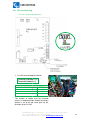
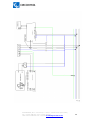
CCL-CP1E/B ELECTRIC VEHICLE CHARGING
SYSTEM IN MODE3 SYSTEM
INSTALLATION AND USER MANUAL
V1.0
CCL-CP1E/B
CP1E/B MODE 3
This document
ment is copyrighted, 2010 - 2012 by Circontrol, S.A. All rights are
reserved. Circontrol, S.A. reserves the right to make improvements to the
products described in this manual at any time without notice.
No part of this manual may be reproduced, copied, translated or transmitted in
any form or by any means without the prior written permission of the original
manufacturer. Information provided in this manual is intended to be accurate
and reliable. However, the original manufacturer assumes no responsibility for
its use, or for any infringements
infringements upon the rights of third parties that may result
from its use.
All other product names or trademarks are properties of their respective owners.
V1.0 Edition JAN 2012
CIRCONTROL, S.A. – Innovació, 3 – 08232 – Viladecavalls (Barcelona)
Tel.: +34 937 362 940 – Fax: +34 937 362 941
Web: www.circo
rcontrol.com – E-mail: [email protected]
2
CONTENTS:
INSTALLATION AND USER MANUAL ............................................................................................ 1
1
OVERVIEW ................................................................................................................................
................................
..................................... 4
2
SYSTEM DESCRIPTION ................................................................................................
................................
................................................... 5
3
SAFETY INFORMATION ................................................................................................
................................
.................................................. 7
4
INSTALLATION ...............................................................................................................................
................................
............................... 8
4.1
4.2
4.3
4.4
5
PREVIOUS VERIFICATION ................................................................................................
................................
.................................................... 8
ANCHORING AND DIMENSIONS
DIMENSI
................................................................................................
........................................... 8
DIMENSIONS FOR CCL-CP1E/B
CP1E/B MOD3................................................................
............................................................. 9
ELECTRICAL INSTALLATION
ON. GENERAL CONSIDERATIONS ................................................................
......................................... 10
USER GUIDE ................................................................................................................................
................................
................................. 11
5.1
NORMAL CHARGE OPERATIVE ................................................................................................
........................................... 11
5.1.1 Charge operation for Models with RFID reader and display
CCL CP1E MOD3. .............. 11
CCL-CP1E
5.1.2 Start of charge cycle ................................................................................................
............................................. 13
5.1.3 End of charge cycle (Normal end) ................................................................
......................................................... 13
5.1.4 End of charge cycle (end of credit)................................................................
........................................................ 13
5.1.5 End of charge cycle (missing charge end) ................................................................
............................................. 14
5.2
RETRIEVE CREDIT OPERATIVE
TIVE ................................................................................................
............................................ 14
5.2.1 Previous cycle interrupted card ............................................................................................
............................ 14
5.3
MISSING CREDIT OPERATIVE
IVE ................................................................................................
............................................. 15
5.3.1 Start of charge cycle ................................................................................................
............................................. 15
5.3.2 Display indications ................................................................................................
................................................ 15
5.4
CHARGE OPERATION FOR MODEL WITHOUT RFID READER CCL-CP1EB MOD3. ......................................
................................
15
6
6 MANTENANCE ................................................................................................
................................
.......................... 16
6.1
GENERAL DESCRIPTION ................................................................................................
................................
................................................... 16
6.2
DISASSEMBLY ................................................................................................................................
................................
................................ 17
6.3
ASSEMBLING ................................................................................................................................
................................
................................. 18
6.4
PREVENTIVE MAINTENANCE
MAINTENANC ................................................................................................
............................................. 19
6.4.1 MONTHLY: ............................................................................................................................
................................
............................ 19
6.4.2 YEARLY: ................................................................................................................................
................................
................................. 19
6.5
CORRECTIVE MAINTENANCE
MAINTENANC ................................................................................................
............................................. 20
6.5.1 Problems – Causes – Solutions ..............................................................................................
.............................. 20
6.6
SPARED PARTS AND RECOMMENDED
MMENDED TOOLS ................................................................
......................................................... 21
6.7
AUTO-DIAGNOSTIC. DISPLAY CODE ................................................................................................
.................................... 22
6.8
ELECTRICAL WIRING ................................................................................................
................................
........................................................ 23
6.9
CONNECTION
TION CONFIGURATION. ................................................................................................
........................................ 25
7
TECHNICAL DATA ................................................................................................
................................
......................................................... 27
8
APPENDIX ................................................................................................................................
................................
.................................... 28
8.1
9
RECOMMENDED SECTION CABLE................................................................................................
........................................ 28
ASOCIATIONS ................................................................................................
................................
.......................... 29
CIRCONTROL, S.A. – Innovació, 3 – 08232 – Viladecavalls (Barcelona)
Tel.: +34 937 362 940 – Fax: +34 937 362 941
Web: www.circo
rcontrol.com – E-mail: [email protected]
3
1 OVERVIEW
This user manual provides basic information about the electric vehicle charging unit:
the CCL-CP1E/B MOD3, according to EN 61851-1.
61851
Important instructions will be shown inside a box. In some cases, these will include
special symbols. Their meaning
aning is explained next:
IMPORTANT INSTRUCTION!
WARNING! DANGER! ELECTRICAL RISK!
CIRCONTROL, S.A. – Innovació, 3 – 08232 – Viladecavalls (Barcelona)
Tel.: +34 937 362 940 – Fax: +34 937 362 941
Web: www.circo
rcontrol.com – E-mail: [email protected]
4
2 SYSTEM DESCRIPTION
The CCL-CP1E/B MOD3 charge units provide to electric vehicles a plug base according to
EN 61851-1.
Comparing with a simple plug CCL-CP1E/B MOD3 offers the following:
-
-
-
-
Safe collection of energy for the installation’s operator. Prevents fraud and
misuse.
Reliable measurement system for the user, since only the energy consumed is
paid, with an accurate reading of the energy consumed.
Protects end user against electrical risks. Current is only present in a nonnon
interrupted charging cycle. The system is not powered during all other cycles.
cycles
Current theft prevention function. The operation is interrupted if the socked is
removed during the charging process, so that no more energy will be supplied
to the base until the user is identified again. Ensure the power supply is
stopped before the physical disconnection of the connector.
Intelligent charging process (off-peak
(off peak hours, distribution of power available,
etc.)
tc.) when complemented with the PC and in hourly discrimination periods.
Let not exceed the maximum permissible current of the cable. (Insurance for
the car does not have an overload, by recognizing of type of car that is
connected). (MODE3
MODE3)
Dosing of the power available through a Duty Cycle. Allowing a power control
that recharge point can supply, depending of the contracted power line.
(MODE3)
Reports the need for vehicle ventilation. Allows determining the battery type of
the car, connected to the charging
charging point and depending on this, and the
location of the site, knowing the type of load acceptable by the vehicle.
(MODE3)
The system is complemented with:
-
Pre-paid
paid cards. Available without credit (to recharge later) and pre-charged
pre
with
5, 20, 50 or 99 units of credit.
Pre-paid
paid card writer. There are three models available:
o
o
o
Integral model, capable of accepting credit cards and notes, CCL-Cash
CCL
Compact, CCL-Term
CCL
software version with USB peripheral, CCL-Soft
CCL
The CCL-CP1E/B MOD3 complies with the CE requirements, and the current European
Union directives for this type of equipments.
The main standards that have been taken into account during the design phase are as
follows:
UNE EN 62196-1: Bases, sockets, vehicle coupling devices and vehicle access
points.
ints. Electric vehicle conductive charging. Part 1: Charging electrical vehicles of up to
250A in alternating current and 400A in direct current.
CIRCONTROL, S.A. – Innovació, 3 – 08232 – Viladecavalls (Barcelona)
Tel.: +34 937 362 940 – Fax: +34 937 362 941
Web: www.circo
rcontrol.com – E-mail: [email protected]
5
UNE EN 61851-1: Electric Vehicle Conductive Charging System. Part 1: General
requirements.
UNE
EN 61851-21:
21: Electric
ectric
Vehicle
Conductive
Charging
System.
Part 21: Requirements of the electric vehicle for its conductive connection to the main
in A.C. and D.C.
UNE
EN 61851-22:
22: Electric Vehicle Conductive
Part 22: A.C. charging station for electric vehicles.
Charging
System.
Other Standards: IEC61000, IEC60364-4-41,
IEC60364
IEC60884-1,
1, IEC61010, UNE-EN55011,
UNE
ISO14443A
In accordance with these Standards, the MULTIPOINT SYSTEM has been designed
for MODE1 charging system, as described in the 61851 Standard:
system with 30mA sensitivity is obligated for these systems.
Vehicles cannot be charged if these systems are not
installed.
This unit has been designed for outdoor use. It has an IP65
IP
protection degree, in
accordance with ANSI/IEC 60529-2004.
60529
CIRCONTROL, S.A. – Innovació, 3 – 08232 – Viladecavalls (Barcelona)
Tel.: +34 937 362 940 – Fax: +34 937 362 941
Web: www.circo
rcontrol.com – E-mail: [email protected]
6
3 SAFETY INFORMATION
-
Do not use connection cables that are not in perfect working order.
-
Do not use the CCL-CP1E/B
CP1E/B MOD3for
MOD3for other uses that have not been specified in its
design, i.e., for any application that is unrelated to charging electric vehicles.
-
Do not modify the CCL-CP1E/B
CP1E/B MOD3 unit. In case the unit is modified, the warranty
will be void and CIRCONTROL shall not be liable for any future malfunction.
-
Strictly follow the current safety regulations.
-
Do not repair or install elements while the unit is powered.
-
Only authorised and trained personnel can access the elements powered with
voltages inside the unit.
-
Check the operation of the earth leakage relay periodically (at least once a month)
and always after maintenance operations.
-
The installation must
ust be checked once a year by qualified personnel.
-
Any unit with defects or faults that could represent a risk to the user must be
removed from service (broken plugs, lids that do not close, etc.).
-
Do not use spare parts that are not original of CIRCONTROL.
CIRCONTROL
CIRCONTROL, S.A. – Innovació, 3 – 08232 – Viladecavalls (Barcelona)
Tel.: +34 937 362 940 – Fax: +34 937 362 941
Web: www.circo
rcontrol.com – E-mail: [email protected]
7
4 INSTALLATION
4.1 Previous verification
•
•
•
Make sure that the materials have not been damaged during transport.
Make sure that the voltage used on the board is suitable for the place/country
where it will be operating.
Make sure that the connection bases are suitable for the place/country where
the unit will be operating.
operating
4.2 Anchoring and dimensions
The CCL-CP1E/B MOD3 is designed to be anchored to the wall and is expected to 4 points for
attachment.
Not providing the anchor material as this will depend on the material where it will be anchored
the box. The anchoring operation is the same as in any electrical panel in common use.
To open the box lid it has to be used the type key of screw that it was delivered to its proper
maintenance and so does not cause premature degradation.
CIRCONTROL, S.A. – Innovació, 3 – 08232 – Viladecavalls (Barcelona)
Tel.: +34 937 362 940 – Fax: +34 937 362 941
Web: www.circo
rcontrol.com – E-mail: [email protected]
8
4.3 Dimensions for CCL-CP1E/B
CCL
MOD3
*Status
Status indicators
*RFiD Receiver
*MODE3 Indicators
*Type 2 connector
CIRCONTROL, S.A. – Innovació, 3 – 08232 – Viladecavalls (Barcelona)
Tel.: +34 937 362 940 – Fax: +34 937 362 941
Web: www.circo
rcontrol.com – E-mail: [email protected]
9
installation General considerations
4.4 Electrical installation.
Qualified professionals must undertake all activities related to the electrical installation,
regardless of whether a project is needed or not, depending on the power installed.
This unit has been designed for its use in a single-phase
single
230Va.c. and three-phase 400Va.c. with a ±10% tolerance.
In
n any case, the end user must be protected against
indirect contact with a residual voltage relay (DDR or
differences) with a sensitivity of 30mA.
The device already includes 30mA differential protection required, so if it’s necessary to
protect upstream,, it must be selective or time sensitivity. The choice must be made by
responsible for the design of the facility, so that REBT is met and to ensure maximum
system availability.
This device can not be installed in places where there is a risk of explosion (explosive
atmosphere).
The minimum breaking power of the automatic header switch (circuit breaker) must be
4500A.
The following layouts show the outline of the installation in blocks. They are shown
for information purposes only. The installation company will be responsible for
dimensioning the section, protection elements and lengths, in compliance with the
current regulations.
Esta información es únicamente a título informativo, no aceptándose
aceptándose responsabilidad alguna
por cualquier posible daño o perjuicio que la instalación pueda provocar. Es el instalador final
quien deberá elegir (bajo su responsabilidad) la forma de instalación en función de las
variables citadas, especialmente las legalmente
l
exigibles en su país.
There is a ground terminal that must be properly wired to the conductor with the
minimum section of 6mm2. IT
I IS
S VERY IMPORTANT ITS RIGHT CONNECTION AND
ITS DIMENSIONS.
The minimum section of the conductors must be 6mm2, but that will be in function of
the installation conditions (length, ducts,…) may be higher. Consult REBT or the
appendices. The responsibility for the installation corresponds to the authorized
installer that designs and makes.
Depending on the model, the
t
device is able to communicate by Rs--485 compatible
devices, so it will be able to send and receive commands or information.
The Rs-485 network installation must follow the requirements that the standard
prescript, among others, the linear topology, end of line resistor, shielding,
equipotential mass, ... Such communication can be enhanced by connecting to R-440
R
module or multipoint system; data can then be stored and accessed via Ethernet..
CIRCONTROL, S.A. – Innovació, 3 – 08232 – Viladecavalls (Barcelona)
Tel.: +34 937 362 940 – Fax: +34 937 362 941
Web: www.circo
rcontrol.com – E-mail: [email protected]
10
5 USER GUIDE
5.1 Normal charge operative
MODE 3 charging station have three diferent leds indicators GREEN, ORANGE and RED for
indicate estate of equipment..
•
Ready: Indicates
•
Charge: Indicates
•
Fault: Indicates system has found one problem.
sy
system
is ready for charge.
system is charging .
5.1.1 Charge operation for Models with RFID reader and display
CCL-CP1E
CP1E MOD3.
1.Once unit get Power supply, verify unit is ready.
1. Green indicator lights
light in the
marker.
Unit is ready for charging.
charging
2. Connect the electric vehicle with Type 2 connector to the unit.
3. Approach RFID TAG to the unit for charge START.
1. Display will indicates remaining credits
inside Tag.
2. CHARGE indicator lights
light and LCD display
starts to roll.
RFID TAG
Do not unplug connector from Vehicle
till not stop the charge approaching
TAG to the unit.
4.Show RFID Tag to the unit for STOP charge.
5. Now you can unplug electric vehicle.
CIRCONTROL, S.A. – Innovació, 3 – 08232 – Viladecavalls (Barcelona)
Tel.: +34 937 362 940 – Fax: +34 937 362 941
Web: www.circo
rcontrol.com – E-mail: [email protected]
11
5.1.2
.1.2 End of charge cycle.
cycle (Normal end)
1. Present the RFID card to the reader.
2. Cycle is interrupted.
3. Disconnect the charge.
4. The credit not consumed
ed is retrieved to the card. “00”
“00
5. Displays the credit. “00”
6. Remove the card.
5.1.3 End of charge cycle (end of credit)
credit
1. If it’s displayed “o” stopped, indicate
cycle.
Digit 1, channel one NO active. Digit 2, channel
c
two NO active.
2. Present the RFID card to the reader.
3. Disconnect the charge.
4. The creditit is retrieved to the card. “xx”
“xx
5. Displays the credit. “xx”
6. Remove the card.
The following explanation refers to loans used but as a symbol €.
In countries where the currency has a similar magnitude to the EURO (€)
( can be
considered as 1 € or 1 credit.
In countries where the currency is very different order of magnitude to the EURO (€),
( a
conversion can be easily calculated, which for example is 1 credit
credit = 1000 local units. In
that case, speaking of credit makes more sense.
CIRCONTROL, S.A. – Innovació, 3 – 08232 – Viladecavalls (Barcelona)
Tel.: +34 937 362 940 – Fax: +34 937 362 941
Web: www.circo
rcontrol.com – E-mail: [email protected]
12
5.1.2
Start of charge cycle
1. Present the RFID card to the reader.
2. After a while displays the credit value.
3. If the claim is correct, a deposit is deducted from the card and transferred to the
charge.
4. Select the charging shocked
5. Connect the charge.
6. Remove the card.
7. The system connects the power and starts the control of credit as the energy
consumed.
8. The display shows a segment simulating a twisting motion with a speed
proportional to power output.
5.1.3
End of charge cycle (Normal end)
1. Present the RFID card to the reader.
2. Cycle is interrupted.
3. Disconnect the charge.
4. The credit not consumed is retrieved to the card. “xx”€
“xx”
5. Displays the credit. “xx”€
“xx”
6. Remove the card.
5.1.4
End of charge cycle (end
end of credit)
1. If it’s displayed “o” stopped, indicate that the system has stopped the charging
cycle.
Digit 1, channel one NO active. Digit 2, channel two NO active.
2. Present the RFID card to the reader.
3. Disconnect the charge.
4. The credit is retrieved to the card.
car “00”€
5. Displays the credit. “00”€.
“00”
6. Remove the card.
CIRCONTROL, S.A. – Innovació, 3 – 08232 – Viladecavalls (Barcelona)
Tel.: +34 937 362 940 – Fax: +34 937 362 941
Web: www.circo
rcontrol.com – E-mail: [email protected]
13
5.1.5
End of charge cycle (missing
missing charge end)
end
1. In display “0”, indicates system has stop charging system .
Digit 1, channel one NOT
NO active. Digit two, channel two NOT active
e.
2.
3.
4.
5.
6.
Present RFID to reader.
reader
Unplug connectors for charge.
charge
Remnant credit of the unit is returned to the card.
card “xx”€.
Display shows crédit.
crédit “xx”€.
Remove tag.
This Stop mode only can happens after one minute from
f m charge start, if not power
consumption has occurred.
5.2 Retrieve credit operative
(Following
Following Interruption of the charging cycle through no fault of the user)
user
After the interruption outside the client, when it returns to recover the debt, it is
available, whether or not in use the unit for another client, the following operations:
operatio
5.2.1
Previous cycle interrupted card
1. Present the RFID card to the reader.
2. The system looks for the target on to the “TAG” code buffer.
3. Once found retrieves the value of credit that user had before the cycle was
interrupted.
4. Once you update the card, the display shows "rC.
5. Remove the card.
6. The reader unsubscribes in the buffer the "TAG" code of the card.
Once retrieved the credit the card is ready for a new charge cycle.
CIRCONTROL, S.A. – Innovació, 3 – 08232 – Viladecavalls (Barcelona)
Tel.: +34 937 362 940 – Fax: +34 937 362 941
Web: www.circo
rcontrol.com – E-mail: [email protected]
14
5.3 Missing credit operative
5.3.1
Start of charge cycle
1. Present the RFID card to the reader.
2. After a while it displays the credit value.
3. If the credit is not correct, the display show “00”€
“00” during 2s and doesn’t start any
new cycle.
4. Remove the card.
5.3.2
Display indications
“rC” – Credit retrieve.
“Ex” – Error x.
“ . ” – Channel indication that it is on resting time. (During this time there is no reading
card for this channel.
“O” – The output is on charge cycle if oscillates vertically. Stationary cycle, while
standing.
5.4 Charge operation for Model without RFID reader CCL-CP1EB
CCL
MOD3.
1. Once unit is powered , please verify unit is ready to work.
1. Green indicator lightss in the
marker.
Unit is ready for charging.
2. Plug connector Type 2 to the unit and connect other side to Electrical Vehicle
1. Unit will start with safety
communications between car and unit.
62. CHARGE indicator lights,
light charge starts.
Stop charge mode unplugging Type 2
connector from the unit.
CIRCONTROL, S.A. – Innovació, 3 – 08232 – Viladecavalls (Barcelona)
Tel.: +34 937 362 940 – Fax: +34 937 362 941
Web: www.circo
rcontrol.com – E-mail: [email protected]
15
MANTENANCE
6.1
General Description
The vehicles charge system CCL-CP1E/B MOD3 is an electrical and mechanical set able
to offer charge service safely both indoors and public places and hold a continuous use
recharge service.
- CCL-CP1E/B MOD3, one type 2 output parking box with communication.
CIRCONTROL, S.A. – Innovació, 3 – 08232 – Viladecavalls (Barcelona)
Tel.: +34 937 362 940 – Fax: +34 937 362 941
Web: www.circo
rcontrol.com – E-mail: [email protected]
16
6.2 Disassembly
To get access inside the CCL-CP1E/B charger is necessary to open the back lid,
depending on model, with Allen screws.
NOTE: Must use Allen wrench to screw supplied appliances for proper maintenance
and do not cause premature degradation.
degradation
are able to be manipulated and the
Once CCL-CP2 is opened the electrical devices are
guidance system hat.
To continue with the removal, follow the following sequence:
1. Disconnect the power supply before disconnect electrical intervention. Only
trained personnel are authorized, and with the precautions and appropriate
ap
personal protective equipment.
2. If it’s not possibly to take the whole power supply, for example because there
are others posts on charge, disconnect the power supply from local area
through de RCCB.
3. ATENTION WITH THE DISCONNECTION PROCESS!
a. Press
ress the test button. This test will show if the RCCB works correctly
(sensibility). Is recommended to do in each intervention.
b. If the RCCB has not jumped, stop until the fault has been repaired by
trained personnel. Remember that the test button does not work if the
residual circuit breaker is not powered.
c. Remember that the RCCB input terminals can be powered so it has to
be careful to avoid manipulation closer it. Do not do any operation if
there are faulty cables, insulation damage or vulnerability of any
a party
liable to be powered.
4. Disconnect the ground cable.
CIRCONTROL, S.A. – Innovació, 3 – 08232 – Viladecavalls (Barcelona)
Tel.: +34 937 362 940 – Fax: +34 937 362 941
Web: www.circo
rcontrol.com – E-mail: [email protected]
17
6.3 Assembling
1. Carry out the same steps in reverse order of removal.
2. DO NOT FORGET THE GROUND
GR
CABLE RECONNECTION.
3. To proceed to testing RCCB should be reconnected again
4. ATTENTION WITH THE RCCB CONNECTION PROCESS!
a. If the power supply was cut upstream,
up
, supply the devices to test the
RCCB.. If it is not possible to supply it just raise the handle to rearm the
RCCB.
b. If long time passed between the disconnection operations RCCB, should
do the sensitivity test again as indicated in the previous section.
Proceed to press the test button.
c. If keeps not running, treat the incident as a failure, with the protocol
established by those.
5. Replace the lid and set it correctly.
CIRCONTROL, S.A. – Innovació, 3 – 08232 – Viladecavalls (Barcelona)
Tel.: +34 937 362 940 – Fax: +34 937 362 941
Web: www.circo
rcontrol.com – E-mail: [email protected]
18
6.4 Preventive mainttenance
The recommended preventive maintenance and his frequency is the following:
6.4.1
-
MONTHLY:
Sensibility test.
Make sure that the RCCB works correctly. We recommend test it causing a
current leakage in one plug (is not necessary to test it on both).
6.4.2
YEARLY:
REMEMBER TO REMOVE POWER!
-
-
-
Do the monthly RCCB preventive maintenance.
Check the electrical wiring is correctly, there are no obvious faults in the
insulation or defects on the components.
Check the proper tightening of the screws on the power
power components,
compone
especially
the RCCB (if it’s provided) and circuit breakers to which access is provided. Use
the right tool on each case.
General cleaning on the electrical components area and the lower hat area.
Remove with a brush the dust. Clean inside the card reader with the brush or o
tissue.
Check the connection state base is correct.
correct
CIRCONTROL, S.A. – Innovació, 3 – 08232 – Viladecavalls (Barcelona)
Tel.: +34 937 362 940 – Fax: +34 937 362 941
Web: www.circo
rcontrol.com – E-mail: [email protected]
19
6.5 Corrective
orrective maintenance
6.5.1
•
Problems – Causess – Solutions
METERING CURRENT PROBLEMS
PRO
o
If no credits discounts despite consumption. Then the toroidal
transformer is probably assembled incorrectly.
incorrectly Solution: Check and
correct if necessary.
It could be problems with the corresponding card energy control (the main
or auxiliary). If it is appropriate
appropriate replace it, remember that it must also
replace the corresponding toroidal transformer. Attention to assembling the
toroidal transformer because it has polarity. The ground wire must pass the
toroidal brown side.
It is also important whatever the type of electronic card to replace, to verify
that the original bridges have inserted, and reproduce in the spare card. Do
not replace any card under supply or with a different type.
o
•
If there is no reaction when the card is inserted, probably it not
recognizes the card or it is empty.
COMUNICATION PROBLEMS ( COM)
COM
The communication follows always the same order:
X2 communicates with R-440.
R
R-440
440 communicates with modem. Modem
communicates with the network. Obviously the posts which don’t have R-440
R
or
modem do not apply to them what is said.
o
Behind a communication interruption check as the following order,
depending with the material that the CCL-CP2 incorporates:
The COM led of the X2 card Works correctly (see on electrical
wirings peg.).
peg.) The communication with R-440
440 works when is
flashing.
When the R-440
R 440 communicates with the X2, the led Tx and Rx
are flashing.
I case that doesn’t work, check the twisted cable Rs-485
Rs
has
reliability and is will connected.
Terminal A = (+), Terminal B =( -)
Check the R-440
R
configuration is charged correctly. It
I is
necessary to know the PowerStudio and connect by modem or
Ethernet cable (inverted).
CIRCONTROL, S.A. – Innovació, 3 – 08232 – Viladecavalls (Barcelona)
Tel.: +34 937 362 940 – Fax: +34 937 362 941
Web: www.circo
rcontrol.com – E-mail: [email protected]
20
•
OTHER
HER PROBLEMS
PROBLEM
o
o
If there is nothing displayed when a valid card is introduced probably
there is no voltage. The REC2 jumped or the power supply has been
interrupted upstream.
When charge is requires and there is a rC on the display it is not a real
problem. The charge does not start because the card is recovering the
credit. That credit was saved because the previous load that card
car ended
incidents.
6.6 Spared
pared parts and recommended tools
The required tools to perform proper preventive or corrective maintenance are the
normal installation electrician. The PPE (Personal Protective Equipment) are also
common, and should be designed by the Prevention Service employee responsible
who makes the assistance.
The following mentioned tools are the only not commonly used:
•
Flat brush with long hair.
The amount and type of recommended spare parts are described in the following list:
list
o
o
o
o
o
o
o
o
Main card control. If this card is replaced, also replace the toroidal. The
spare card brings its own toroidal. We recommend having 1 unit per 10
CCL-CP1E/B.
Auxiliary card. If it is replaced, also replace his toroidal. The spare card
brings its own toroidal.
toroidal. We recommend having 1 unit per 10 CCL-CP1E/B.
Auxiliary MODE3 card. We recommend having 1 unit per 10 CCL-CP1E/B.
Plug bases. We recommend having 2 units per 10 CCL-CP1E/B
CP1E/B.
RBC. Check the sensibility of the RCCB is 30mA. (=0,030A). We
recommend having 1 unit per 10 CCL-CP1E/B.
Power relay. We recommend having 2 units per 10 CCL-CP1E/B
CP1E/B.
Overcurrent
ent protector. We recommend having 2 units per 10 CCL-CP1E/B
Allen screws of the lid. We recommend having 30 units per 10 CCLCP1E/B.
CIRCONTROL, S.A. – Innovació, 3 – 08232 – Viladecavalls (Barcelona)
Tel.: +34 937 362 940 – Fax: +34 937 362 941
Web: www.circo
rcontrol.com – E-mail: [email protected]
21
6.7 Auto-diagnostic. Display code
2 9
8 8
Software version is displayed for 1 second after unit is connected to the electrical supply
Indicates credit avalible when the RFID card is presented to the card reader. Example '88'
9 9
When the credit number is flashing '99' this indicates that the credit value is greater than 99
L
Socket 1. Allows charging regardless of avaliable credit. This option only works with a suitably
formatted card and the correct software upgrade in the charging equipment
L
Socket 2. Allows charging regardless of avaliable credit. This option only works with a suitably
formatted card and the correct software upgrade in the charging equipment
Socket 1. 'H' indicates that the charging unit has reached the preset time limit. This feature can
be enabled or disabled by the factory using the charging equipment software
H
H
Socket 2. 'H' indicates that the charging unit has reached the preset time limit. This feature can
be enabled or disabled by the factory using the charging equipment software
Socket 1. '0' flashing indicates the charging unit has reached the preset time allowed for a
minimum charge
o
o
Socket 2. '0' flashing indicates the charging unit has reached the preset time allowed for a
minimum charge
It draws a card of the channel 1, properly updated or insert a card that is not correct
.
.
It draws a card of the channel 2, properly updated or insert a card that is not correct
Socket 1. A segment fixed in one position indicates there is no load. When the segment is
rotating it indicates charging. The speed of the rotation indicates the amount of load
-
Socket 2. A segment fixed in one position indicates there is no load. When the segment is
rotating it indicates charging. The speed of the rotation indicates the amount of load
r C
Credit recovery failed in a previous cycle. Reset the system
E 1
Communication failed with RFID card reader
E 2
RFID Reader unable to read card
E 3
Not Used
E 4
RFID Reader unable to write to card
The information that appears briefly in the card reader display shows the firmware
version number, i.e. 29 is version 2.9.
Errors "E1, E2, E4" have automatic recovery.
CIRCONTROL, S.A. – Innovació, 3 – 08232 – Viladecavalls (Barcelona)
Tel.: +34 937 362 940 – Fax: +34 937 362 941
Web: www.circo
rcontrol.com – E-mail: [email protected]
22
6.8 Electrical wiring
-
X2 Card.
ard. Topographic distribution.
1. Rs-485
485 twisted cable connection:
Terminal A (brown) = (+)
Terminal B (white) = (-)
(
Rs-485
485 TACHNICAL CHARACTERISTICS
Speed
Default address
Default nº of nodes
Stop bit
57600bps
A98
98
8n1
The number of nodes must be changed
when it is integrated into a network by factory
default is set at 98, the same goes for the
direction of the Rs-485.
CIRCONTROL, S.A. – Innovació, 3 – 08232 – Viladecavalls (Barcelona)
Tel.: +34 937 362 940 – Fax: +34 937 362 941
Web: www.circo
rcontrol.com – E-mail: [email protected]
23
CIRCONTROL, S.A. – Innovació, 3 – 08232 – Viladecavalls (Barcelona)
Tel.: +34 937 362 940 – Fax: +34 937 362 941
Web: www.circo
rcontrol.com – E-mail: [email protected]
24
6.9 Connection
onnection configuration.
1. Connect the input connection in monophasic
asic or Threefasic configuration to contactor,
please be careful with phases L1,L2,L3,neutral as show the figure.
PHASES
ASES L1,L2,L3
GROUND
NEUTRAL
Figure 1. Threephase connection detail for CCL-CP1EB MOD3
CIRCONTROL, S.A. – Innovació, 3 – 08232 – Viladecavalls (Barcelona)
Tel.: +34 937 362 940 – Fax: +34 937 362 941
Web: www.circo
rcontrol.com – E-mail: [email protected]
25
X2+MODE3 cards for MODE3. Topographic distribution.
CIRCONTROL, S.A. – Innovació, 3 – 08232 – Viladecavalls (Barcelona)
Tel.: +34 937 362 940 – Fax: +34 937 362 941
Web: www.circo
rcontrol.com – E-mail: [email protected]
26
7 TECHNICAL DATA
Rate input frequency
50… 60 Hz
Output Voltage
= Input voltage
Power meter
Internal meter
RFID Reader
ISO 14443A
Range Temperature
-10… 60 oC
Protection IP
IP65
Envelope
ABS
Input Voltage
230V/400Vc.a. L+N+PE ±10 %
Maximun current
32A
Maximun consumption
7,2kW
Mode3 connector
Type 2
Dimensions
320mm; 225mm; 125mm
Weight
3Kg
CIRCONTROL, S.A. – Innovació, 3 – 08232 – Viladecavalls (Barcelona)
Tel.: +34 937 362 940 – Fax: +34 937 362 941
Web: www.circo
rcontrol.com – E-mail: [email protected]
27
8 APPENDIX
8.1 Recommended section cable
CIRCONTROL, S.A. – Innovació, 3 – 08232 – Viladecavalls (Barcelona)
Tel.: +34 937 362 940 – Fax: +34 937 362 941
Web: www.circo
rcontrol.com – E-mail: [email protected]
28
9 ASOCIATIONS
Our group belongs to and is actively involved in various committees on the Electric
Vehicle:
• CHAdeMO Association (International Association works for the standardization of
charging stations for electric vehicles). Certified members.
• ASESGA (Spanish Association of Car Parks and Garages). Technology Committee.
• AFME (Association of Electrical Manufacturers).
Manufacturers). Electric Vehicle Working Group.
• CEEC (Cluster Energy Efficiency Catalunya). Electric Mobility Group.
• AMEC URBIS (Spanish Association of Urban Equipment and Traffic). Electric Vehicle
Commission.
• Forever (Spanish Forum Electric Vehicle).
• AEDIVE
VE (Association of Business Innovative Electric Vehicle Infrastructure).
CIRCONTROL, S.A. – Innovació, 3 – 08232 – Viladecavalls (Barcelona)
Tel.: +34 937 362 940 – Fax: +34 937 362 941
Web: www.circo
rcontrol.com – E-mail: [email protected]
29