1
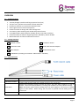
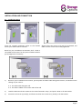
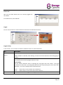
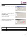
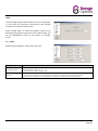
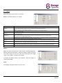
IP CAMERA PRO INSTRUCTION MANUAL For the latest, up-to-date manual, please visit www.storageoptions.com IMPORTANT SAFEGUARD All lead-free products offered by the company comply with the requirements of the European law on the Restriction of Hazardous Substances (RoHS) directive, which means our manufacture processes and products are strictly “lead-free” and without the hazardous substances cited in the directive. The crossed-out wheeled bin mark symbolizes that within the European Union the product must be collected separately at the product end-of-life. This applies to your product and any peripherals marked with this symbol. Do not dispose of these products as unsorted municipal waste. Contact your local dealer for procedures for recycling this equipment. DISCLAIMER We reserve the right to revise or remove any content in this manual at any time. We do not warrant or assume any legal liability or responsibility for the accuracy, completeness, or usefulness of this manual. The content of this manual is subject to change without notice. GROUNDING This is a Safety Class 1 Product (provided with a protective earthing ground incorporated in the power cord). The mains plug shall only be inserted in a socket outlet provided with a protective earth contact. Any interruption of the protective conductor inside or outside of the instrument is likely to make the instrument dangerous. Intentional interruption is prohibited. TRADEMARK ACKNOWLEDGEMENTS Internet Explorer, Microsoft, Windows, Mozilla & QuickTime are registered trademarks of the respective holders. MPEG4 LICENCING THIS PRODUCT IS LICENSED UNDER THE MPEG4 VISUAL PATENT PORTFOLIO LICENSE FOR THE PERSONAL AND NON-COMMERCIAL USE OF A CONSUMER FOR (i) ENCODING VIDEO IN COMPLIANCE WITH THE MPEG4 VISUAL STANDARD (“MPEG-4 VIDEO”) AND/OR (ii) DECODING MPEG4 VIDEO THAT WAS ENCODED BY A CONSUMER ENGAGED IN A PERSONAL AND NON-COMMERCIAL ACTIVITY AND/OR WAS OBTAINED FROM A VIDEO PROVIDER LICENSED BY MPEG LA TO PROVIDE MPEG4 VIDEO. NO LICENSE IS GRANTED OR SHALL BE IMPLIED FOR ANY OTHER USE. ADDITIONAL INFORMATION INCLUDING THAT RELATING TO PROMOTIONAL INTERNAL AND COMMERCIAL USES AND LICENSING MAY BE OBTAINED FROM MPEG LA, LLC. SEE HTTP://WWW.MPEGLA.COM. WARRANTY AND TECHNICAL SUPPORT In the event that you need further assistance with this product you can call us, at local UK rate on the number below and our UK-based experts will be happy to help you (they’re available Mon-Fri 9am – 5.30pm, excluding bank holidays). Alternatively visit our website at www.storageoptions.com/support or send us an email at the address below. This product is backed by a 12 month warranty to cover the unlikely event of something going wrong. Should you suspect a fault with your product please contact our support team in the first instance. UK: 0844 2487191 Ireland: 00353 (0) 94 937 4026 E-Mail: [email protected] Page 2 TABLE OF CONTENTS OVERVIEW 4 1.1 – Product Features 1.2 – Package Contents 1.3 – Cable Overview 4 4 4 INSTALLATION AND CONNECTION 5 2.1 – Install The Camera 2.2 – Connect To Power 5 6 BEFORE USING YOUR NETWORK CAMERA 7 ACCESSING THE CAMERA VIA VIDEO VIEWER 8 4.1 – Accessing The Camera 4.2 – Control Panel Overview 4.3 – Frequently Used Functions 8 8 10 SYSTEM CONFIGURATION 13 5.1 – General 5.2 – Network 5.3 – Video 5.4 – Camera 14 16 18 19 ACCESSING THE CAMERA VIA YOUR WEB BROWSER 20 6.1 – Accessing The Camera 6.2 – Control Panel Overview 20 21 ACCESSING THE CAMERA VIA YOUR MOBILE PHONE 23 7.1 – Checklist Before Using 7.2 – Program Download / Installation 7.3 – Program Setup 23 23 24 CREATING AN ACCOUNT FOR DDNS SERVICE 25 APPENDIX - PRODUCT SPECIFICATIONS 27 Page 3 OVERVIEW 1.1 – Product Features True Day & Night surveillance & large aperture lens (F1.4) The best cost / performance outdoor solution with IP65 IR effective distance up to 30 metres with 56 IR LEDs Smart Light Control to avoid overexposure Excellent outdoor ID design with cable management Low-latency video streaming with H.264 compression format Free CMS software with E-Map for multiple devices control & surveillance Powerful mobile surveillance supporting iPhone, BlackBerry, WinCE & J2ME Motion detection and alarm notification functions 1.2 – Package Contents Network Camera Installation Sticker Installation Guide RJ45 Cable Extender Adapter Mains Adapter RJ45 Network Cable CD-ROM Disc (including user manuals “Video Viewer” software) 1.3 – Cable Overview CABLE RJ45 Network Cable Reset Wires Power Cable DESCRIPTION Connect it to the supplied RJ45 cable extender adapter for cable extension, and prepare another RJ45 network cable with suitable length for your connection. Remove the insulating coating of these two wires, and twist them together to reset to default. This will reset all parameters, including the IP address to factory default settings. Note: Disconnect power before twisting these two wires together, and connect to power again to reset default. When fitting, you may wish to provide internal cabling access to these wires Connect to DC 12V power supply. Page 4 INSTALLATION AND CONNECTION 2.1 – Install The Camera Paste the supplied installation sticker to the location Slightly fasten the screws to (a) and (b) as indicated, and where your camera will be installed. make sure the screws are not fully tightened. Based on your installation environment, drill a hole in the middle of the sticker for the power and data cable to put through later if necessary. 1) Based on your installation environment, put the power and data cable through the bracket, and determine the cabling of your camera: 3-1: The cable walks along the wall 3-2: The cable is hidden on the other side of the wall 2) Hook the bracket with the camera to the screws fastened in step 2, and push it down to fix the bracket. 3) Secure the screws on (a) and (b), and fasten the other two screws to (c) and (d) to fix the bracket. Page 5 Adjust the angles of the camera: (e) Adjust the vertical angle of the camera, and fix it with the screw and wrench supplied with the socket. (f) Loosen the screw a little on the camera joint with the supplied wrench to adjust the horizontal angle of the camera, then re-tighten to fix it in place. 2.2 – Connect To Power Connect the power adapter to the camera’s power connector and power outlet. Page 6 BEFORE USING YOUR NETWORK CAMERA Before using the network camera, make sure: 1) You have installed the supplied CMS software, “Video Viewer”. 2) You have configured the network settings, and the network connection is fine. If not, please refer to the Quick Start Guide for instructions on how to do this. The camera can be accessed via supplied CMS software “Video Viewer”, or via Web browser such as “Microsoft Internet Explorer” or “Mozilla Firefox”, depending on different using situations. To check or configure up to 16 surveillance devices simultaneously with the record function, please use “Video Viewer”. For details about using Video Viewer, please refer to “ACCESSING THE CAMERA VIA VIDEO VIEWER” on page 8, and “SYSTEM CONFIGURATION” on page 13. To view or configure this network camera only, it’s recommended to use a web browser such as “Microsoft Internet Explorer” or “Mozilla Firefox”. For details about using the web browser, please refer to “ACCESSING THE CAMERA VIA YOUR WEB BROWSER” on page 20. Page 7 ACCESSING THE CAMERA VIA VIDEO VIEWER 4.1 – Accessing The Camera Step 1: Double-click on your PC desktop to open Video Viewer. By default, the “Address Book” panel will be displayed on the right side of the control panel. Step 2: Click “ ” to select the IP address of the camera you intend to connect, and double-click it. Step 3: The live view is displayed in the Video Viewer 4.2 – Control Panel Overview Two control panels are available and can be switched depending on your using habit. Simple Version: Page 8 Full Function Version: Main Button Overview: Button Simplified Full Function Function Description Address book Click to show the predefined IP address(es). You can add, remove or search the IP address to log in the DVR remotely. Miscellaneous control / / Remote config Record setting Custom setting Click to go to the detailed system configuration. Click to go to the detailed record setting. Click to choose the language of this program, or set the password when activating this program. Log Click to view all event and recording logs, search the desired log(s) by date, or playback the recording of the selected log. Record / Stop Click to start / stop the manual recording. The record button will be disabled when the reserved disk capacity set in “Record Setting” is larger than the current disk capacity. Snapshot Click to take a snapshot of the current view. The snapshot will be saved in the path you specified in “Record Setting”. Information Click to show the current network connection details. Page 9 4.3 – Frequently Used Functions Record: To record, click “ ” or “ ”→“ ” to go to the “Record Setting” page. In the “Record Setting” page, you can set the following items: Record type Pre / post-event record time (0~10 seconds) Record time setting Record path Note: The record function will be disabled when the reserved disk capacity in “Reserved(MB)” is larger than the current disk capacity in “Free(MB)”. When “Manual” is checked, click “ ” or “ ” on the main control panel to start the manual recording immediately, and the recordings will be saved in the location specified in “Record Path”. When “Motion” and / or “Alarm” are checked, the recording function will be enabled for any motion or alarm event, and the recordings will be saved in the location specified in “Record Path”. You can also set a recording schedule from the “Record Setting” page, by setting colour coded blocks of time. Schedule: Alarm: Motion: Page 10 Playback: To play a recording, click “ ” or “ ”, and select the “Record” tab. A list of all the recordings will be shown by default, and you can also sort the logs by date, start time, end time, etc, by simply clicking the column header. Page 11 Firmware Upgrade: This function allows the user to upgrade to the latest version of the camera’s firmware. Note: Before using this function, make sure you have the correct upgrade files from www.storageoptions.com. Step 1: Click “ Step 2: Click “ ” and select the IP address of your network camera in the address book. ” to show the upgrade page, “Update Server”. Step 3: Click “Add” to browse to the upgrade files. Step 4: Click “Upgrade Firmware” to start firmware upgrade. Note: The firmware upgrade process should take a few minutes. Do not disconnect the power during this time, or the upgrade may fail. The camera will reboot after the upgrade. Page 12 SYSTEM CONFIGURATION Before using the network camera, make sure you have installed the supplied “Video Viewer” software, and configure the camera’s network settings. If not, please refer to your installer. Note: You need to use the administrator account to enter the system configuration page. If you are logged in as a user, please sign out and re-log into the camera using an admin account. Click “ ” and select “ ” to enter the system configuration page. All the system configurations are listed as a tree structure on the left panel as follows. Main Menu Sub Menu Functionality 1. Check the firmware version and MAC address of the camera. 2. Change the camera title. General Log Check the system event logs. Account 1. Create a new user account with different access privilege. 2. Modify or delete an existing user account. Online User Check the current online user(s). Trigger 1. Enable / disable the motion detection. 2. Set the motion detection area. 3. Select the event notification method. Network Configure network settings. QoS Limit the data flow for live streaming. DDNS Enter DDNS information when the network type is PPPOE or DHCP. SNTP Synchronize your camera time with the networked computer systems. FTP Enter the FTP information for event notifications when “FTP” is chosen in “General” → “Trigger”. Mail Enter Email information for event notifications when “Email” is chosen in “General” → “Trigger”. Filter Choose to permit or block the IP address(es) which can access this camera. UPnP Allow this camera to be detected among devices within the same network area for easy and quick usage. Video Set the image resolution, quality and frame rate. Camera Adjust the camera parameters if necessary. Colour Adjust the color performance. Time Set daylight saving time and the current time. Page 13 5.1 – General In “General”, you can check the general information for your IP camera, such as the firmware version and MAC address, and also modify the identification name of your camera (up to 15 alphanumeric characters). Log: To quickly search the system log by event type, click the drop-down list to select the system log type you want to check, and click “Reload” to refresh the list. To clear all system event logs, click “Clear”. Account: You can create a new account with different user access privilege, or delete / modify an existing account setting. DO NOT ATTEMPT TO DELETE THE ADMIN ACCOUNT. Step 1: Click “New”, and fill in the following information. Option User Name: Password: User Level: Life Time: Desciption Set a user name that will be used for camera access. The user name can be up to 16 alphanumeric characters. Set the password that will be used for remote login. The password can be up to 16 alphanumeric characters. Set the permission level of an account to give access to control different functions. There are four user levels: Supervisor, Power, Normal and Guest. Select how long this account is allowed to stay online. (1 / 5 / 10 / 60 mins / 1 day / infinite) Step 2: Click “Apply” to save your settings and create the new account. Page 14 Online User: Here you can check which users are currently logged into the camera. To refresh the list, click “Refresh”. Trigger: You can set the motion or alarm detection and select the notification function. Trigger Setting: In this section, you can select to enable or disable the alarm or motion detection. Item Motion: Description Select to enable or disable the motion detection function. When “Enable” is selected, click “Setting” to enter the motion detection area setting page as follows: Sensitivity: Set the detection sensitivity (High / Normal / Low). Area Setting: Set the motion detection area by selecting the area grids with your mouse. Pink grids represent the area that is not being detected while the transparent grids are the area under detection. You can set multiple areas under detection. Duration: Click “-” (Clear All) to set the whole area undetected. Click “+” (Select All) to set the whole area under detection. Set the duration time for trigger recording (5 / 10 / 20 / 40 seconds). Page 15 5.2 – Network You can set the network configuration of the IP camera depending on your network type. For more details, please refer to the Quick Start Guide. QoS: Quality of Service is the ability to control the data flow for real-time streaming. This function is important if your network bandwidth is insufficient and you have other devices that share bandwidth. To use QoS, check “QoS Enable” and set the maximum upload rate from 256 to 10240 kbps. DDNS: Select “On” when the selected network type in “Network” is “PPPOE” or “DHCP”. For details, please refer to “CREATING AN ACCOUNT FOR DDNS SERVICE” on page 25. SNTP: Simple Network Time Protocol is used to synchronize your camera time with the networked computer systems. Function Description GMT: Once users choose the time zone, the network camera will adjust the local area time of the system automatically. Server Name: Simply use the default SNTP server (For example, tock.stdtime.gov.tw) or change to another server with which users are familiar. Sync Period: Select “Daily” to synchronize the camera time with the network time every day or “None” to turn off this function. Sync Server Time: Click and the network camera will synchronize the time with the network time. Page 16 Mail: Enter the details of an e-mail account you wish to use for notifications and click “Apply” to confirm. The information you set here will be applied when “Email” is selected in “General” → "Trigger". Function Description Server: Enter the SMTP server address provided from your e-mail system supplier. Port: Enter the port number provided from your e-mail system supplier. If this is left blank, the e-mail server will default to port 25. Mail From: Enter the entire mail address to ensure e-mails will not be blocked by SMTP. SSL Encryption: Select “Yes” if your e-mail server is using SSL encryption to protect your e-mail content from unauthorized access. Verify Password: Some mail servers are required to verify the password. Please enter the “user name” and “password”. E-Mail Address: Add the e-mail address(s) of the assigned recipient(s). Filter: Choose to permit or block the IP address(es) which can access this camera. Function Description Error Login Count: Set the maximum count for login failure. When the maximum count is reached, the IP address trying to access the network camera will be locked. Error Lock Time: Set the lock time in minutes when the maximum count of error login for an IP address is reached. Echo Request: Select “Non-Block” to allow other users to use the ping command to detect the IP address of your network camera, or “Block” to deny the ping command request. Filter: Choose to enable (YES) or disable (NO) the filter function. If “YES” is selected, choose whether you want to permit (Allow) or block (Deny) the IP address list below. Apply: To add an item to the IP address list, key in the IP address in “IP Address”, and click “Add”. To remove an existing item in the IP address list, click the item you want to remove, and click “Delete”. Click “Apply” on the bottom right corner when any change is made in this menu, or the change will not be recorded in the system. Page 17 UPnP: Universal Plug and Play allows devices to connect seamlessly in the home and corporate environments and simplify installation of computer components. Check “Enable UPnP” to allow the network camera to be detected among devices within the same network area, and set the identification name of the camera in “Friendly name”. 5.3 – Video Set the image resolution, quality and frame rate. Item Description JPEG / MPEG / H.264: Select the image resolution and quality. Image Resolution: CIF / 4CIF Image Quality: BEST / HIGH / NORMAL / LOW Frame Rate: The frame rate allowed to each viewer can be adjusted to adapt to the bandwidth on the network. Set the desired image frequency to the maximum (FULL) or to a specified frame rate: (1/2; 1/3; 1/4; 1/5; 1/10; 1/15; 1/20; 1/25; 1/30). The actual frame rate depends on the actual network connection, and may be lower than the specified one. Page 18 5.4 – Camera Adjust the camera parameters if necessary. Note: To preview changes, click “Apply”. Item Backlight: Mirror: IR Control: White Balance: Brightness: Sharpness: Colour: AGC: Default: Description The backlight is adjustable to compensate for an area that is overpowered by brightness because of excessive light. The image will be properly exposed for clearness. Select to activate (ON) or disable (OFF) this function. Note: This function is only available in day mode. Mirror is used when you want to flip the images horizontally based on your installation situation. The options are: ON / OFF. Select “IR PRO” to smartly activate the IR LEDs when needed, “Always On” to always activate the IR LEDs, or “Always Off” to deactivate the IR LEDs. The white balance function processes the current image to retain colour balance over a colour temperature range. According to different colour temperatures and installation situations, set the white balance function to a suitable mode. The options are: Auto / AWB1 / AWB2 / AWB3. Brightness helps to adjust the image based on different lighting conditions. Click and drag the slider to adjust the brightness. Applicable values are from 0~127. The larger the value, the brighter the image. Sharpness enhances the clarity of image detail by adjusting the aperture and sharpening the edges in the pictures. Click and drag the slider to adjust the sharpness. Applicable values are from 2~15. The larger the value, the sharper the image. Colour helps to adjust the image saturation through the camera. Click and drag the slider to adjust the colour level. Applicable values are from 0~127. The larger the value, the thicker the image. Adjusts the amplitude of the signal input according to different light conditions. Click and drag the slider to adjust the amplitude of the signal input. Applicable values are from 0~255. The larger the value is, the more the signal noise there will be. Click to restore all changes to default values. Colour: Adjust the colour performance of the camera, including Brightness, Contrast, Hue and Saturation. Click and drag the slider to preview the colour change on the live view panel and adjust the image colour. Click “Apply” to confirm the change. To restore the default values, click “Default”, and click “Apply” to confirm the change. Time: Set daylight saving time and the current time. Page 19 ACCESSING THE CAMERA VIA YOUR WEB BROWSER It is also possible to access the IP camera via a web browser, such as Microsoft Internet Explorer or Mozilla Firefox. However, you can only access one camera at a time through a Web browser. If you wish to view multiple cameras, please use the included “Video Viewer” software. Alternatively, you can open separate tabs / windows for each camera in your Web browser. Before using the network camera, make sure you have configured the network settings and have the camera’s IP address, user name and password to hand. If not, please refer to the installation guide. 6.1 – Accessing The Camera Step 1: Open your web browser, and key in http://ipaddress:portnum in the URL address box. For example, for IP address 192.168.1.10 and port number 81, please key in ”http://192.168.1.10:81” into the URL address box, and press “Enter”. Step 2: In the login page, key in the user name and password, and enter the security code from the image below. Click “LOGIN” to access camera controls. Step 3: The wizard will analyze your network environment. To continue setting the password, date & time, and network, click “Next” and follow the step-by-step instructions. To skip the wizard and directly access the camera live view, click “Close”. To directly access the camera live view without starting the wizard for the next login, check “Do not start wizard at login”. Step 4: When you have logged in successfully, the camera’s live view is shown. Page 20 6.2 – Control Panel Overview Live View Panel: Function Icon User Level Description Select the web transmission format from the drop-down list: H.264 / MPEG-4 / Motion JPEG / QuickTime Media Type Video Quality Video Resolution Snapshot Flip Full Screen Supervisor Power / Normal User Guest Supervisor Power / Normal User Supervisor Power / Normal User Supervisor Power / Normal User Supervisor Power / Normal User Supervisor Power / Normal User For users using Mozilla Firefox, only “QuickTime” is selectable. QuickTime is Apple Inc.’s multimedia software. You need to have QuickTime installed on your operating system before selecting “QuickTime”. When it is selected, you will be promoted to enter the user name and password to access the camera. Click & drag the slider to select the video quality: Basic / Normal / High / Best Select the video resolution from the drop list: 4CIF / CIF. Click to take a snapshot for the current view, and a new browser window will be opened to display the captured image. Click to flip the image 1800 anti-clockwise when necessary. Click to display the image in full screen. Page 21 System Configuration Panel: Click “Configuration” to enter the configuration page. Note: You need to be the supervisor to enter the system configuration page. If not, please re-log into the camera with an admin account. The functions are categorized into three menus: Network, Camera and General. For details about “General”, please refer to “5.1 – General” on page 14, and “5.3 – Video” on page 18. For details about “Network”, please refer to “5.2 – Network” on page 16. For details about “Camera”, please refer to “5.4 – Camera” on page 19. Main Menu Sub Menu Network Network Remote Config Network QoS Remote Config Network QoS DDNS Remote Config Network DDNS SNTP Remote Config Network SNTP FTP Remote Config Network FTP Mail Remote Config Network MAIL Filter Remote Config Network Filter UPnP Remote Config Network UPnP Colour Remote Config Colour Time Remote Config Time Advance Remote Config Camera General Remote Config Custom Setting Server Log Remote Config General Log Login Remote Config General Account Account Remote Config General Account Trigger Remote Config General Trigger Video Remote Config Video Camera General Upgrade Reference For details, please refer to “Firmware Upgrade” on page 6. Page 22 ACCESSING THE CAMERA VIA YOUR MOBILE PHONE 7.1 – Checklist Before Using Make sure your PDA or mobile phone conform to the following requirements: Device Make Sure... The operating system is Windows Mobile 5.0 Packet PC / 6.0 Professional*. Windows Mobile 5.0 Smartphone / 6.0 Standard is NOT supported. WinCE-Based PDA J2ME MIDP2.0 is supported. Internet services via Wireless or GPRS / 3G networks are subscribed and available to use. For details, please check with your local network operator or service provider. J2ME is supported. J2ME-Based Mobile Phone Internet services via GPRS / 3G networks are subscribed and available to use. For details, please check with your local network operator or service provider. The port number of the connected device is NOT 80. The suggested port number is 88. Internet services via 3G networks are subscribed and available to use. For details, please check with your local network operator or service provider. iPhone Your mobile phone is available to access “App Store”. * We do not guarantee the compatibility of the mobile surveillance software in every touch panel PDA brand with the operating system of Windows Mobile 5 Packet PC / 6.0 Professional. Please check with your distributor for details. 7.2 – Program Download / Installation For iPhone: Step 1: Go to “App Store” via your iPhone, and search our program with one of the following keywords: EagleEyes PTZ IPCAM Surveillance Note: You might be charged for Internet access via wireless or 3G networks. For the Internet access rate details, please check with your local network operator or service provider. Step 2: Follow the on-screen instructions to download and install the program. “ desktop for quick access when the program is installed successfully. ” will be shown on the iPhone Page 23 For WinCE & J2ME Based Mobile Phone: Step 1: To download the program for mobile surveillance, please visit the following website address from your PDA or mobile phone: http://www.storageoptions.com/mobile Note: The Internet access setting via wireless or GPRS / 3G networks varies depending on different PDA or mobile phone brand. For details, please refer to its individual user manual, or check with your local network operator or service provider. Note: You may be charged for Internet access via wireless or GPRS / 3G networks. For the Internet access rate details, please check with your local network operator or service provider. You will see the following four programs are available: GPRS_3G_Software: EagleEyes (J2ME_NewVersion): EagleEyes (for WinCE): EagleEyes (for WinCE NewVersion): J2ME AP for Network MJPEG format DVR J2ME AP for Network MPEG/H.264 format DVR & IP camera WinCE AP for Network MJPEG format DVR WinCE AP for Network MPEG4/H.264 format DVR & IP camera) Step 2: Download the program as instructed: Select “EagleEyes (J2ME New version)” if you’re using the J2ME-based mobile phone. Select “EagleEyes (For WinCE New Version)” if you’re using the WinCE-Based PDA phone. Step 3: Follow the on-screen instructions after downloading. For mobile phones, the program will be saved to the location you specified. For WinCE-Based PDA, the program will be saved in “Programs”. 7.3 – Program Setup Step 1: Get the necessary information for accessing your network camera, such as the IP address, user name, password, port number, etc. Step 2: Activate the program, and go to its setting page to fill in the information needed. Step 3: Try to access your network camera to see if the connection works. Page 24 CREATING AN ACCOUNT FOR DDNS SERVICE For PPPOE or DHCP, you should enter the host name which points to the IP address of your network camera for login first. Besides using the default DDNS service, you can also apply for new DDNS services. There are many websites that offer free DDNS service application. Below is an example of DDNS account application from the website http://www.dyndns.com. 1) Go to http://www.dyndns.com, and click “Create Account” to sign up a DDNS account. 2) Enter all the information necessary for signing up an account according to the website instructions. Key in a user name for login, for example, headoffice523. Set the password and input it again to confirm. Key in your E-mail address and input it again to confirm. Then, click “Create Account”. 3) The system will automatically send a confirmation email to your email account. Please read this email within 48 hours and complete the procedure to activate your account according to the instructions in the email. 4) Click “login”, and enter the user name and password. Page 25 5) Click “Add Host Services”. Input a meaningful host name. Choose a host system name. Enter the IP address you want to redirect. Note down the whole host name, for example, headoffice523.dyndns.org. Then, click “Add To Cart” for billing. Note: This service is free. Just finish the billing process, and NO payment information is required. 6) Click “Activate Services” after checkout, and your to use DDNS services will be ready to use. 7) Return to Video Viewer, and go to “Network” “DDNS”. Select “On” for DDNS. Select the system name you set when subscribing the DDNS service from the drop-down list, for example, “dyndns”. Enter the user name and password you used to log into the DDNS service. Enter the host name you set when subscribing to the DDNS service, for example, headoffice523. Page 26 APPENDIX - PRODUCT SPECIFICATIONS Network Network Compression H.264, QuickTime, MPEG4, M-JPEG LAN Port Yes LAN Speed 10/100Mbps Ethernet Supported Protocols DDNS, PPPoE, DHCP, NTP, SNTP, TCP/IP, ICMP, SMTP, FTP, HTTP, RTP, RTSP Frame Rate NTSC: 30 PAL: 25 Number Of Online Users 10 Security Multiple user access levels with password Web Management (1) Web browsers, such as Internet Explorer, Mozilla FireFox, or Google Chrome for single device access (2) Free CMS software, Video Viewer, for up to 16 network cameras control simultaneously Camera Image Sensor 1/3" HR colour CCD image sensor Pixels 768(H) x 494(V) <NTSC> / 752(H) x 582(V)) <PAL> Minimum Illumination 0.05 Lux / F1.4, 0 Lux (IR ON) Shutter Speed 1 / 60 (1/50) to 1 / 100,000 sec. S/N Ratio More than 48dB (AGC off) Lens f6.0mm Viewing Angle 480 IR LED 56 units IR Effective Range Up to 40 metres Smart Light Control Yes White Balance ATW AGC Auto IRIS Mode AES IP Rating IP65 Power Source (±10%) DC 12V / 1.5A Others Mobile Surveillance iPhone, BlackBerry, J2ME & WinCE Motion Detection Yes Alarm & Event Notification FTP and E-Mail Minimum Requirements Pentium 4 CPU 1.3 GHz or higher, or equivalent AMD 256 MB RAM AGP graphics card, Direct Draw, 32MB RAM Windows Vista, XP, Windows 2000 Server, ME, 98, DirectX 9.0 or later Internet Explorer 6.x or later Page 27 Page 28