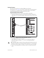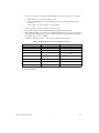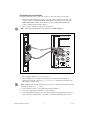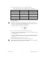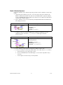
1
CALIBRATION PROCEDURE
NI PXIe-4353
Français
Deutsch
ni.com/manuals
This document contains information about verifying and adjusting National Instruments NI PXIe-4353
modules using NI-DAQmx 9.3 and later. It also contains information about verifying systems that
include both the NI PXIe-4353 and TB-4353. For more information about calibration, visit
ni.com/calibration.
Contents
Software ............................................................................................................................................... 1
Documentation..................................................................................................................................... 2
Calibration Interval .............................................................................................................................. 2
Test Equipment .................................................................................................................................... 2
Test Conditions .................................................................................................................................... 3
NI PXIe-4353 Calibration Procedure .................................................................................................. 3
Initial Setup for the NI PXIe-4353 .............................................................................................. 4
Verifying Module Operating Temperature Changes ................................................................... 4
Verification Procedure................................................................................................................. 5
Analog Input Voltage Accuracy Verification...................................................................... 5
Analog Input Offset Verification......................................................................................... 7
CJC Resistance Accuracy Verification................................................................................ 8
Module Calibration Adjustment .................................................................................................. 10
Test Limits ........................................................................................................................................... 13
Module Verification Test Limit Tables ....................................................................................... 13
Where to Go for Support ..................................................................................................................... 15
Software
Install NI-DAQmx 9.3 or later on the calibration computer. NI-DAQmx includes high-level function
calls to simplify the task of writing software to calibrate modules. You must have the proper module
driver installed on the calibration system before calibrating the module.
Note NI recommends that you install the NI-DAQmx driver software before physically installing
the NI PXIe-4353. NI-DAQmx, available at ni.com/downloads, configures and controls the
NI PXIe-4353.
NI-DAQmx supports a number of programming languages, including LabVIEW, LabWindows™/CVI™,
C/C++, C#, and Visual Basic .NET.
You can access the NI-DAQmx header file, NIDAQmx.h, like any standard library. You can find
examples of how to use the NI-DAQmx driver by entering the Info Code NIDAQmxExLoc at
ni.com/info there you will find the topic Where Can I Find NI-DAQmx Examples?
Documentation
The following documents are your primary references for writing your calibration utility with
NI-DAQmx. You can download the latest version of these documents from the NI Web site at
ni.com/manuals.
•
The NI SC Express 4353 Installation Guide and Terminal Block Specifications provides
instructions for installing and configuring the NI PXIe-4353 module and TB-4353 accessory.
•
The NI PXIe-4353 User Manual describes how to use the NI PXIe-4353.
•
The NI PXIe-4353 Specifications lists the specifications for the NI PXIe-4353.
•
The CAL-4353 Specifications lists the specifications for the CAL-4353.
•
The NI-DAQmx Help includes information about creating applications that use the NI-DAQmx
driver.
•
The NI-DAQmx C Reference Help includes information about the functions in the driver.
Calibration Interval
National Instruments recommends a calibration interval of one year for the NI PXIe-4353. You should
adjust the recommended calibration interval based on the measurement accuracy demands of your
application.
Test Equipment
National Instruments recommends that you use the instruments in Table 1 for calibrating an
NI PXIe-4353 module.
Table 1. Recommended Equipment
Equipment
Recommended Model
Requirements
Voltage calibrator
Fluke 5520A
If this instrument is unavailable for voltage accuracy verification and
adjustment, use a high-precision voltage source with an accuracy of at
least 70 ppm when sourcing up to 50 μA.
Resistance calibrator*
Fluke 5520A
If this instrument is unavailable for resistance accuracy verification and
adjustment, use a high-precision resistance source with an accuracy of
at least 150 ppm 2-wire compensation.
If the resistance source does not have 2-wire compensation, the lead
wire resistance must be included in the total resistance source accuracy.
PXI Express chassis
NI PXIe-1062Q
—
Calibration accessory
CAL-4353
This accessory is used for module verification and adjustment.
Connecting wires
Banana-jack
terminated copper wire
Copper wire is used for validating the voltage accuracy and adjustment
of the analog input channels. Copper wire is also used for validating the
resistance accuracy and calibration of the CJC resistance input
channels.
* When connecting the resistance calibrator, keep the lead wires 1.0 Ω less than the maximum lead compensation specification of the resistance
calibrator. When using the Fluke 5520A, keep the lead wires <1.1 Ω.
NI PXIe-4353 Calibration Procedure
2
ni.com
Test Conditions
The following setup and environmental conditions are required to ensure the module meets published
specifications.
•
Keep connections to the module as short as possible. Long cables and wires act as antennas, picking
up extra noise that can affect measurements.
•
Use shielded wire for all cable connections to the module. Use twisted-pair wire to eliminate noise.
•
Maintain an ambient temperature of 23 °C ±5 °C. The module temperature will be greater than the
ambient temperature.
•
Keep relative humidity below 80%.
•
Allow a warm-up time of 15 minutes to ensure that the measurement circuitry of the NI PXIe-4353
and CAL-4353 are at a stable operating temperature.
Note
If you are using the Fluke 5520A, allow the calibrator to warm up for 30 minutes and maintain
an ambient temperature of 23 °C ±3 °C.1
•
Ensure that the PXI Express chassis fan speed is set to HIGH, that the fan filters are clean, and that
the empty slots contain filler panels. For more information, refer to the Maintain Forced-Air
Cooling Note to Users document available at ni.com/manuals.
NI PXIe-4353 Calibration Procedure
This section provides instructions for verifying the voltage accuracy performance of the NI PXIe-4353.
The calibration process consists of the following steps:
1.
Initial Setup for the NI PXIe-4353—Install the module and configure it in Measurement &
Automation Explorer (MAX).
2.
Verifying Module Operating Temperature Changes—Verify that the current module operating
temperature will not cause you to incorrectly calibrate your module.
3.
Verification Procedure—Verify the existing operation of the module. This steps confirms whether
the module is operating within its specified range and whether it needs adjustment.
4.
Adjustment—If the module does not fall within the desired specifications, perform the adjustment
procedure. This will adjust the module calibration constants. If the module does fall within the
desired specifications, but the module has reached its calibration time interval since the last
calibration adjustment, perform the adjustment procedure. Otherwise, performing the adjustment
procedure is optional.
5.
Reverification—Repeat the verification procedure to ensure that the module is operating within the
published specifications after adjustment.
The first four steps are explained in the following sections.
1
Refer to the Fluke 5520A user manual for the latest set up requirements and recommendations to achieve the best accuracy.
© National Instruments
3
NI PXIe-4353 Calibration Procedure
Initial Setup for the NI PXIe-4353
You must configure the module in Measurement & Automation Explorer (MAX) to communicate with
NI-DAQmx.
Complete the following steps to configure a module in MAX. Refer to the NI SC Express 4353
Installation Guide and Terminal Block Specifications for complete installation instructions.
1.
Install the NI-DAQmx driver software.
Caution
Always have the PXI Express chassis powered off when inserting a module.
2.
Insert the module into an available slot in the PXI Express chassis.
3.
Attach the CAL-4353 to the NI PXIe-4353.
Note
The CAL-4353 must be within its calibration interval and if it is not, you must calibrate the
CAL-4353 before calibrating the NI PXIe-4353 module.
4.
Power on the chassis.
5.
Launch MAX.
6.
Expand Devices and Interfaces to confirm that MAX detects the module and terminal block.
The terminal block should appear beneath its associated module.
7.
Right-click NI PXIe-4353 and select Self-Test to ensure that the module is working properly.
Note
You can also perform the self-test operation programmatically, using the DAQmx Self-Test
Device VI or the equivalent C/.NET functionality.
Verifying Module Operating Temperature Changes
A module operating temperature greater than ±10 °C since the previous calibration adjustment can
cause you to incorrectly calibrate your module. The onboard temperature sensor on the module can be
used to verify that this condition does not exist. Complete the following steps to compare the current
module temperature to the temperature measured during the last calibration.
1.
Launch MAX.
2.
Select My System»Devices and Interfaces»Chassis 1»NI PXIe-4353.
Note MAX assigns a chassis name for each chassis in an application. This document uses Chassis 1.
In your application, use the appropriate name assigned to your chassis by MAX.
3.
Click the Calibration tab.
If the difference between the current operating temperature and the operating temperature from the
last calibration adjustment is greater than 10 °C, the limits in the calibration tables are not valid.
Note You can also query the temperatures programmatically, using the DAQmx Calibration Info
property node or the equivalent C/.NET functionality.
Note
The temperature reading returned by the module is an internal temperature. Typically, the
internal temperature is approximately 10 °C warmer than the ambient temperature.
If the module temperature difference is outside the maximum range, you should choose one of the
following options:
•
Recalculate the test limits to include the additional error due to temperature drift. Refer to the
NI PXIe-4353 Specifications for more information.
•
Change the system so that the operating temperature will be closer to the temperature recorded
during the last calibration adjustment.
NI PXIe-4353 Calibration Procedure
4
ni.com
Verification Procedure
This section provides instructions for verifying the NI PXIe-4353 specifications.
Tables 4 through 7 in the Test Limits section show all acceptable settings for the module. Throughout
the verification process, use Tables 4 through 7 to determine if the module is operating within its
specified range. Perform verification on all analog input and CJC channels.
Analog Input Voltage Accuracy Verification
Complete the following steps to test the voltage accuracy performance of the module.
1.
Using banana-jack terminated copper wire, connect the positive and negative terminals of the
voltage calibrator to the terminals labeled INPUT V Ω HI and LO of the CAL-4353 while referring
to Figure 1.
5520A CALIBRATOR
HI
INPUT 30 VDC
MAX
VΩ
NORMAL
AUX
V, , ,RTD
A, -SENSE, AUX V
SCOPE
OUT
LO
HI
20V
RMS
MAX
1V PK
MAX
150V
PK
MAX
LO
TRIG
20V
RMS
MAX
HI
SENSE 30 VDC
MAX
Ω
LO
GUARD
20A
TC
20V PK MAX
SHELLS
NOT
GROUNDED
20V
PK
MAX
20V PK MAX
Figure 1. CAL-4353 to Fluke 5520A Calibrator Connections
2.
Open a DAQmx calibration session on your device.
3.
Call the DAQmx Connect SC Express Calibration Accessory Channels VI. Configure the
CAL-4353 by setting the connection to _tc_calibration and the physical channels
to Dev1/ai0:31.
Note When MAX configures a module, it is assigned a module name. Each function call uses this
module name to determine the correct module to adjust. This document uses Dev1 when referring to
the module name. When you calibrate your module, use the module name assigned to it by MAX.
4.
If you are not using a Fluke 5520A, set the calibrator voltage to a Test Point value indicated in
Table 4.
© National Instruments
5
NI PXIe-4353 Calibration Procedure
5.
To reduce the loading error when using a Fluke 5520A, set the voltage range to 3.3 V as follows:
a.
On the front panel, set the output voltage to 2.0 V.
b.
Press the 3.3 V Auto button, which will display 3.3 V locked. The output will no longer
auto-range.
c.
Set the output to the desired voltage level using Table 4.
6.
Create and configure AI voltage channels you want to verify.
7.
Set the autozero mode to Every Sample and disable open thermocouple detection.
8.
On the DAQmx Channel property node, set the DAQmx ADC timing mode property to Custom and
set the ADC custom timing mode property to a value from the first column of Table 4. To determine
which timing mode to select, use Table 4.
9.
Configure the timing properties for a finite voltage acquisition. Refer to Table 2.
Table 2. DAQmx Timing Function Rate and Samples per Channel
Timing Mode
Rate (S/s)
Samples per Channel
1
1
16
2
2
16
3
4
20
4
8
40
5
16
80
6
32
120
7
90
300
10. Start the acquisition.
NI PXIe-4353 Calibration Procedure
6
ni.com
11. Acquire the voltage data.
Note Make sure the calibrator and the NI PXIe-4353 are completely settled at the desired voltage
before acquiring data. When using the Fluke 5520A, wait at least 5000 ms for the system to settle
before issuing the start task command to the NI PXIe-4353.
Note You must set the read timeout value to something larger than the default, such as 20.0 seconds,
or you will get a timeout error.
12. Average the voltage values for each channel that you acquired. Compare the resulting average to
the Upper Limit and Lower Limit values in Table 4. If the result is between these values, the module
passes the test.
13. Clear the acquisition.
14. Repeat steps 4 through 13 for all test point values in Table 4. NI recommends that you verify all
values, although you can save time by verifying only the values used in your application.
15. Close the DAQmx calibration session with the action Cancel.
16. Disable the calibrator output and disconnect the calibrator from the module.
Analog Input Offset Verification
Complete the following steps to test the performance of the analog input offset of the module.
1.
Open a DAQmx calibration session on your device.
2.
Call the DAQmx Connect SC Express Calibration Accessory Channels VI. Configure the
CAL-4353 by setting the connection to _short_tc_terminals and the physical channels to
Dev1/ai0:31.
3.
Set voltage calibrator output to 0 V.
4.
Complete steps 6 through 13 of the Analog Input Voltage Accuracy Verification section to test the
performance of analog input offset of the module. Repeat these steps for all timing modes.
5.
Compare the resulting average to the Upper Limit and Lower Limit offset values in Table 5.
NI recommends that you verify all values, although you can save time by verifying only the values
used in your application.
6.
Repeat steps 6 through 13 of the Analog Input Voltage Accuracy Verification section with autozero
mode set to None in step 7. Repeat these steps for all timing modes.
7.
Compare the resulting average to the Upper Limit and Lower Limit offset values in Table 6.
NI recommends that you verify all values, although you can save time by verifying only the values
used in your application.
8.
Close the DAQmx calibration session with the action Cancel.
Note After verifying your module, you can update the last calibration date by opening a DAQmx
external calibration session and closing it with the action Commit.
© National Instruments
7
NI PXIe-4353 Calibration Procedure
CJC Resistance Accuracy Verification
Complete the following steps to test the CJC resistance accuracy performance of the module.
1.
Using banana-jack terminated copper wire, connect the positive and negative terminals of the
resistance calibrator to the INPUT V Ω HI and LO inputs of the CAL-4353. Also connect the
SENSE Ω HI and LO terminals of the CAL-4353 to the Sense HI and LO terminals of the
resistance calibrator while referring to Figure 2.
2.
Set the resistance calibrator to 2-wire compensation mode.
Note
When using the Fluke 5520A, set the calibrator to 2-WIRE COMP mode.
5520A CALIBRATOR
HI
INPUT 30 VDC
MAX
VΩ
NORMAL
AUX
V, , ,RTD
A, -SENSE, AUX V
SCOPE
OUT
LO
HI
20V
RMS
MAX
150V
PK
MAX
LO
TRIG
20V
RMS
MAX
HI
SENSE
Ω
LO
GUARD
20V PK MAX
20A
TC
SHELLS
NOT
GROUNDED
20V
PK
MAX
20V PK MAX
Figure 2. CAL-4353 to Fluke 5520A Calibrator Connections
3.
Open a DAQmx calibration session on your device.
4.
Call the DAQmx Connect SC Express Calibration Accessory Channels VI. Configure the
CAL-4353 by setting the connection to _cjc_calibration and the physical channels to the
CJC channel you want to verify.
Note Qualify the CJC channel name by the device name. For example, the physical channel name
must have the format Dev1/_cjtemp0.
5.
Set the calibrator resistance to a Test Point value indicated in Table 7.
6.
Create and configure the CJC channel for voltage acquisition.
7.
Set the ADC timing mode property to Custom and set the ADC custom timing mode property to a
value from the first column of Table 3. Use Table 3 to determine which timing mode to select.
NI PXIe-4353 Calibration Procedure
8
ni.com
8.
Configure the timing properties for the voltage acquisition. Refer to Table 3.
Table 3. DAQmx Timing Function Rate and Samples per Channel for CJC Verification
9.
Timing Mode
Rate (S/s)
Samples per Channel
1
17
10
2
34
10
3
68
20
4
90
35
5
90
50
6
90
80
7
90
150
Start the acquisition.
10. Acquire the voltage data.
Note Make sure that the calibrator and the NI PXIe-4353 are completely settled on the desired
resistance before acquiring data. When using the Fluke 5520A, wait at least 5000 ms for the system
to settle before issuing the start task function to the NI PXIe-4353.
11. Calculate the equivalent resistance using the following equation:
40 kΩ
R CJC = ---------------------------2.048 V
------------------- – 1
V CJC_ave
where VCJC_ave is the average of the voltage values for the channel you acquired.
12. Compare the resulting average to the Upper Limit and Lower Limit values in Table 7. If the result
is between these values, the channel passes the test.
13. Clear the acquisition.
14. Repeat steps 5 through 12 for all CJC channels and test point values in Table 7. NI recommends
that you verify all values, although you can save time by verifying only the values used in your
application.
15. Close the DAQmx calibration session with the action Cancel.
16. Disable the calibrator output and disconnect the calibrator from the CAL-4353.
Note After verifying your module, you can update the last calibration date by opening a DAQmx
external calibration session and closing it with the action Commit.
© National Instruments
9
NI PXIe-4353 Calibration Procedure
Module Calibration Adjustment
Complete the following steps to adjust the input voltage and CJC resistance calibration constants of the
module.
1.
Using banana-jack terminated copper wire, connect the positive and negative terminals of the
INPUT V Ω HI and LO terminals of the CAL-4353 to the Fluke 5520A or equivalent calibrator.
Connect the SENSE Ω HI and LO terminals of the CAL-4353 to the calibrator Sense HI and LO
terminals while referring to Figure 2.
2.
Open a calibration session on your module using the DAQmx Initialize External Calibration VI.
The default password is NI.
LabVIEW Block Diagram
NI-DAQmx Function Call
Call DAQmxInitExtCal with the following parameters:
deviceName: Dev1
password: NI
calHandle: &calHandle
3.
Configure the CAL-4353 using the DAQmx Connect SC Express Calibration Accessory
Channels VI. Set the connection to _tc_calibration and the physical channels
to Dev1/ai0:31.
LabVIEW Block Diagram
NI-DAQmx Function Call
Call DAQmxConnectSCExpressCalAccChans with the
following parameters:
calHandle: calHandle
channelNames: Dev1/ai0:31
connection: _tc_calibration
4.
Set the calibrator to output +70 mV and wait for the calibrator output to settle.
5.
To reduce the loading error when using a Fluke 5520A, set the voltage range to 3.3 V as follows:
a.
On the front panel, set the output voltage to 2.0 V.
b.
Press the 3.3 V Auto button, which will display 3.3 V locked. The output will no longer
auto-range.
c.
Set the output to the desired voltage level using Table 4.
NI PXIe-4353 Calibration Procedure
10
ni.com
6.
Perform an external calibration adjustment by selecting the DAQmx Adjust 4353 Calibration VI,
from the DAQmx Adjust SC Express Calibration polymorphic VI. Set the physical channels
to Dev1/ai0:1. The reference value parameter is the actual output of the calibrator, 70 mV.
LabVIEW Block Diagram
NI-DAQmx Function Call
Call DAQmxAdjust4353Cal with the following parameters:
calHandle: calHandle
channelNames: Dev1/ai0:1
refVal: actual output of the calibrator
7.
Set the calibrator to output –70 mV and wait for the calibrator output to settle.
8.
Perform an external calibration adjustment by selecting the DAQmx Adjust 4353 Calibration VI,
from the DAQmx Adjust SC Express Calibration polymorphic VI. Set the physical channels
to Dev1/ai0:1. The reference value parameter is the actual output of the calibrator, –70 mV.
LabVIEW Block Diagram
NI-DAQmx Function Call
Call DAQmxAdjust4353Cal with the following parameters:
calHandle: calHandle
channelNames: Dev1/ai0:1
refVal: actual output of the calibrator
9.
Disable the calibrator output.
10. Set the resistance calibrator to 2-wire compensation mode.
11. Configure the CAL-4353 using the DAQmx Connect SC Express Calibration Accessory
Channels VI. Set the connection to _cjc_calibration and the physical channels
to Dev1/_cjtemp0.
LabVIEW Block Diagram
NI-DAQmx Function Call
Call DAQmxConnectSCExpressCalAccChans with the
following parameters:
calHandle: calHandle
channelNames: Dev1/_cjtemp0
connection: _cjc_calibration
12. Set the calibrator to resistance mode. Set the calibrator resistance to 32.4 kΩ and wait for the
calibrator output to settle.
© National Instruments
11
NI PXIe-4353 Calibration Procedure
13. Perform an external calibration adjustment by selecting the DAQmx Adjust 4353 Calibration VI,
from the DAQmx Adjust SC Express Calibration polymorphic VI. Set the physical channels to
Dev1/_cjtemp0. The reference value parameter is the actual output of the calibrator, 32.4 kΩ.
LabVIEW Block Diagram
NI-DAQmx Function Call
Call DAQmxAdjust4353Cal with the following parameters:
calHandle: calHandle
channelNames: Dev1/_cjtemp0
refVal: actual output of the calibrator
14. Set the calibrator resistance to 0 Ω and wait for the calibrator output to settle.
15. Perform an external calibration adjustment by selecting the DAQmx Adjust 4353 Calibration VI,
from the DAQmx Adjust SC Express Calibration polymorphic VI. Set the physical channels
to Dev1/_cjtemp0. The reference value parameter is the actual output of the calibrator, 0 Ω.
LabVIEW Block Diagram
NI-DAQmx Function Call
Call DAQmxAdjust4353Cal with the following parameters:
calHandle: calHandle
channelNames: Dev1/_cjtemp0
refVal: actual output of the calibrator
16. Disable the calibrator output.
17. Save the adjustment constants to the EEPROM, using the DAQmx Close External Calibration VI
and set the action to Commit. This VI also saves the date, time, and temperature of the adjustment
to the onboard memory.
Note
If an error occurs during adjustment, no constants will be written to the EEPROM.
LabVIEW Block Diagram
NI-DAQmx Function Call
Call DAQmxCloseExtCal with the following parameters:
calHandle: calHandle
action: DAQmx_Val_Action_Commit
18. Disconnect the calibrator from the module.
Note Partial adjustment of only the TC channels is possible by omitting steps 10 through 16. Partial
adjustment of only the CJC channels is possible by omitting steps 3 through 9.
NI PXIe-4353 Calibration Procedure
12
ni.com
Test Limits
Tables 4 through 7 list the specifications that the NI PXIe-4353 module or NI PXIe-4353 and TB-4353
system should meet if it has been one year between calibrations. The following definitions describe how
to use the information from these tables:
•
Test Point—The voltage value that is input or output for verification purposes. This value is broken
down into two columns, Location and Value. Location refers to where the test value fits within the
test range. Value refers to the voltage or temperature value to be verified. Max refers to maximum
value, Min refers to minimum value, and Mid refers to mid-scale.
•
1-Year Limits—Contains the Upper Limits and Lower Limits for the test point value. That is, when
the module is within its 1-year calibration interval, the test point value should fall between these
upper and lower limit values.
Module Verification Test Limit Tables
Table 4. NI PXIe-4353 Analog Input Voltage Accuracy Verification Test Limits
Test Point
1-Year Limits (V)
Timing Mode
Location
Value (V)
Lower Limit
Upper Limit
1 (High Resolution)
Max
0.070000
0.069970
0.070030
Min
–0.070000
–0.070030
–0.069970
Max
0.070000
0.069970
0.070030
Min
–0.070000
–0.070030
–0.069970
Max
0.070000
0.069970
0.070030
Min
–0.070000
–0.070030
–0.069970
Max
0.070000
0.069969
0.070031
Min
–0.070000
–0.070031
–0.069969
Max
0.070000
0.069960
0.070040
Min
–0.070000
–0.070040
–0.069960
Max
0.070000
0.069959
0.070041
Min
–0.070000
–0.070041
–0.069959
Max
0.070000
0.069958
0.070042
Min
–0.070000
–0.070042
–0.069958
2
3
4
5
6
7 (High Speed)
© National Instruments
13
NI PXIe-4353 Calibration Procedure
Table 5. NI PXIe-4353 Offset with Autozero Enabled Verification Test Limits
Test Point
1-Year Limits (V)
Timing Mode
Location
Value (V)
Lower Limit
Upper Limit
1 (High Resolution)
Mid
0.000000
–0.000002
0.000002
2
–0.000002
0.000002
3
–0.000002
0.000002
4
–0.000003
0.000003
5
–0.000005
0.000005
6
–0.0000065
0.0000065
7 (High Speed)
–0.0000075
0.0000075
Table 6. NI PXIe-4353 Offset with Autozero Disabled Verification Test Limits
Test Point
1-Year Limits (V)
Timing Mode
Location
Value (V)
Lower Limit
Upper Limit
1 (High Resolution)
Mid
0.000000
–0.0000095
0.0000095
2
–0.0000095
0.0000095
3
–0.0000095
0.0000095
4
–0.0000105
0.0000105
5
–0.000013
0.000013
6
–0.0000145
0.0000145
7 (High Speed)
–0.0000155
0.0000155
NI PXIe-4353 Calibration Procedure
14
ni.com
Table 7. NI PXIe-4353 CJC Resistance Accuracy Verification Test Limits
1-Year Limits (Ω)
Test Point
Timing Mode
Location
Value (Ω)
Lower Limit
Upper Limit
1 (High Resolution)
Max
32400
32349.6
32450.4
Mid
10000
9987.0
10013.0
Min
2200
2197.2
2202.8
Max
32400
32349.6
32450.4
Mid
10000
9987.0
10013.0
Min
2200
2197.2
2202.8
Max
32400
32349.6
32450.4
Mid
10000
9987.0
10013.0
Min
2200
2197.2
2202.8
Max
32400
32349.6
32450.4
Mid
10000
9987.0
10013.0
Min
2200
2197.2
2202.8
Max
32400
32349.6
32450.4
Mid
10000
9987.0
10013.0
Min
2200
2197.2
2202.8
Max
32400
32349.6
32450.4
Mid
10000
9987.0
10013.0
Min
2200
2197.2
2202.8
Max
32400
32349.6
32450.4
Mid
10000
9987.0
10013.0
Min
2200
2197.2
2202.8
2
3
4
5
6
7 (High Speed)
Where to Go for Support
The National Instruments Web site is your complete resource for technical support. At ni.com/
support you have access to everything from troubleshooting and application development self-help
resources to email and phone assistance from NI Application Engineers.
National Instruments corporate headquarters is located at 11500 North Mopac Expressway, Austin,
Texas, 78759-3504. National Instruments also has offices located around the world to help address your
support needs. For telephone support in the United States, create your service request at ni.com/
support and follow the calling instructions or dial 512 795 8248. For telephone support outside the
United States, visit the Worldwide Offices section of ni.com/niglobal to access the branch office
Web sites, which provide up-to-date contact information, support phone numbers, email addresses, and
current events.
© National Instruments
15
NI PXIe-4353 Calibration Procedure
CVI, LabVIEW, National Instruments, NI, ni.com, the National Instruments corporate logo, and the
Eagle logo are trademarks of National Instruments Corporation. Refer to the Trademark Information at
ni.com/trademarks for other National Instruments trademarks. The mark LabWindows is used
under a license from Microsoft Corporation. Windows is a registered trademark of Microsoft
Corporation in the United States and other countries. Other product and company names mentioned
herein are trademarks or trade names of their respective companies. For patents covering
National Instruments products/technology, refer to the appropriate location: Help»Patents in your
software, the patents.txt file on your media, or the National Instruments Patent Notice
at ni.com/patents. Refer to the Export Compliance Information at ni.com/legal/
export-compliance for the National Instruments global trade compliance policy and how to
obtain relevant HTS codes, ECCNs, and other import/export data.
© 2012 National Instruments. All rights reserved.
373563A-01
Mar12