1
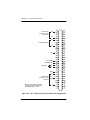
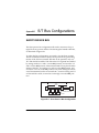
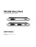
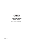
NT1 Type 400 Standalone
Part Number 1212016L1-20
Document Number 61212016L1-20A
September 1999
901 Explorer Boulevard
P.O. Box 140000
Huntsville, AL 35814-4000
Phone: (256) 963-8000
© 1999 ADTRAN, Inc.
All rights reserved.
Printed in USA.
This device complies with Part 15 of the FCC rules. Operation is subject
to the following two conditions: (1) This device may not cause harmful
interference, and (2) this device must accept any interference received,
including interference that may cause undesired operation.
Changes or modifications to this unit not expressly approved by
the party responsible for compliance could void the user's authority to operate the equipment.
Canadian Standards Association
This device must be powered by a CSA approved power supply or a
power supply meeting the requirements of CS03, Part I Section 1.4.2.
Warranties
ADTRAN will repair or replace this product within five years from the
date of shipment if it does not meet its published specifications or fails
while in service. For detailed warranty, repair, and return information,
refer to the ADTRAN Equipment Warranty and Repair and Return Policy Procedure. Return Material Authorization (RMA) is required prior
to returning equipment to ADTRAN. (See inside back cover for phone
number and address to use.)
iii
FCC regulations require that the following information be provided in this manual:
1.
This equipment complies with Part 68 of the FCC rules. On the
bottom of the equipment housing is a label that shows the FCC
registration number and Ringer Equivalence Number (REN) for
this equipment. If requested, provide this information to the telephone company.
2.
If this equipment causes harm to the telephone network, the telephone company may temporarily discontinue service. If possible, advance notification is given; otherwise, notification is given
as soon as possible. The telephone company will advise the customer of the right to file a complaint with the FCC.
3.
The telephone company may make changes in its facilities, equipment, operations, or procedures that could affect the proper operation of this equipment; advance notification and the opportunity
to maintain uninterrupted service is given.
4.
If experiencing difficulty with this equipment, please contact
ADTRAN for repair and warranty information. The telephone
company may require this equipment to be disconnected from
the network until the problem is corrected, or it is certain the
equipment is not malfunctioning.
5.
This unit contains no user-serviceable parts.
6.
An FCC compliant telephone cord with a modular plug is provided with this equipment. In addition, an FCC compliant cable
appropriate for the dial backup option ordered is provided with
this equipment. This equipment is designed to be connected to
the telephone network or premises wiring using an FCC compatible modular jack, which is Part 68 compliant.
7.
The following information may be required when applying to the
local telephone company for leased line facilities.
Service
Type
Digital Facility
Interface Code
Service
Order Code
Network Jacks
ISDN
02IS5
6.0N
RJ-49C
iv
ADTRAN YEAR 2000 (Y2K) READINESS DISCLOSURE
ADTRAN has established a Year 2000 program to ensure that our products and operations will correctly function in the new millennium.
ADTRAN warrants that all products meet Year 2000 specifications
regardless or model or revision. Information about ADTRAN’s Year
2000 compliance program is available at the following:
Web Site
www.adtran.com
Product Matrix
www.adtran.com/Y2Kfax.html
Faxback Document
Line
(256) 963-8200
Y2K plans and product certifications are
listed in the matrix
Y2K Project Line
(256) 963-2200
E-mail
year [email protected]
CUSTOMER INSTRUCTIONS
1.
The mounting of the registered unit in the final assembly must be
made so that the registered unit is isolated from exposure to any
hazardous voltages within the assembly. Adequate separation and
restraint of cables and cords must be provided.
2.
The circuitry from the registered unit to the telephone line must be
provided in wiring that carries no other circuitry unless specifically
allowed by the rules (such as PC and PR leads). PC board traces
carrying tip and ring leads shall have sufficient spacing to avoid
surge breakdown.
3.
A modular plug or jack shall be provided which complies with Part
68, Subpart F requirements for dimensions, tolerances metallic plating.
v
CANADIAN EMISSIONS REQUIREMENTS
This digital apparatus does not exceed the Class B limits for radio
noise emissions from digital apparatus as set out in the interferencecausing equipment standard entitled "Digital Apparatus," ICES-003
of the Department of Communications.
Cet appareil numerique respecte les limites de bruits radioelectriques
applicables aux appareils numeriques de Class B prescrites dans la
norme sur le materiel brouilleur: "Appareils Numeriques," NMB-003
edictee par le ministre des Communications.
vi
CANADIAN EQUIPMENT LIMITATIONS
Notice: The Canadian Industry and Science Canada label identifies certified equipment. This certification means that the equipment meets
certain telecommunications network protective, operational, and safety
requirements. The Department does not guarantee the equipment will
operate to the user’s satisfaction.
Before installing this equipment, ensure that it is permissible to be connected to the facilities of the local telecommunications company. The
equipment must also be installed using an acceptable method of connection. In some cases, the company’s inside wiring associated with a
single-line individual service may be extended by means of a certified
connector assembly (telephone extension cord). Compliance with the
above conditions may not prevent degradation of service in some situations.
Repairs to certified equipment should be made by an authorized Canadian maintenance facility designated by the supplier. Any repairs or
alterations made by the user to this equipment, or equipment malfunctions, may give the telecommunications company cause to request the
user to disconnect the equipment.
Users should ensure for their own protection that the electrical ground
connections of the power utility, telephone lines, and internal metallic
water pipe system, if present, are connected together. This precaution
may be particularly important in rural areas.
Users should not attempt to make such connections themselves,
but should contact the appropriate electric inspection authority,
or an electrician, as appropriate.
The Load Number (LN) assigned to each terminal device denotes the
percentage of the total load to be connected to a telephone loop which is
used by the device, to prevent overloading. The termination on a loop
may consist of any combination of devices subject only to the requirement that the total of the Load Numbers of all devices does not exceed
100.
vii
viii
Table of Contents
Table of Contents . . . . . . . . . . . . . . . . . . . . . . . . . . . . . . . . . . . . . . . . . ix
List of Figures . . . . . . . . . . . . . . . . . . . . . . . . . . . . . . . . . . . . . . . . . . . .xi
List of Tables . . . . . . . . . . . . . . . . . . . . . . . . . . . . . . . . . . . . . . . . . . xiii
Chapter 1 About the NT1 Type 400. . . . . . . . . . . . . . . . . . . . . . . 1-1
Unit Overview . . . . . . . . . . . . . . . . . . . . . . . . . . . . . . . . . . . . . . . . . . 1-1
LED Indicators . . . . . . . . . . . . . . . . . . . . . . . . . . . . . . . . . . . . . . . . .1-1
Basic Rate Description . . . . . . . . . . . . . . . . . . . . . . . . . . . . . . . . . . . . 1-2
Passive Bus Description. . . . . . . . . . . . . . . . . . . . . . . . . . . . . . . . . . . 1-2
Powering TEs from the NT1 . . . . . . . . . . . . . . . . . . . . . . . . . . . . . . . 1-3
Rear Panel . . . . . . . . . . . . . . . . . . . . . . . . . . . . . . . . . . . . . . . . . . . . . . 1-3
Chapter 2 Installation . . . . . . . . . . . . . . . . . . . . . . . . . . . . . . . . . .
Setting the Option Switches . . . . . . . . . . . . . . . . . . . . . . . . . . . . . . .
Powering Up the NT1 Type 400 Standalone . . . . . . . . . . . . . . . . .
Connecting the Terminal Equipment . . . . . . . . . . . . . . . . . . . . . . .
2-1
2-1
2-2
2-3
Chapter 3 Troubleshooting. . . . . . . . . . . . . . . . . . . . . . . . . . . . . .
Maintenance . . . . . . . . . . . . . . . . . . . . . . . . . . . . . . . . . . . . . . . . . . . .
Remote Testing . . . . . . . . . . . . . . . . . . . . . . . . . . . . . . . . . . . . . . . . . .
Repair and Return . . . . . . . . . . . . . . . . . . . . . . . . . . . . . . . . . . . . . . .
3-1
3-2
3-2
3-2
Appendix A NT1 Type 400 Circuit Pack . . . . . . . . . . . . . . . . . . A-1
Appendix B S/T Bus Configurations . . . . . . . . . . . . . . . . . . . . . B-1
Appendix C Specifications . . . . . . . . . . . . . . . . . . . . . . . . . . . . . . C-1
Index
61212016L1-20
. . . . . . . . . . . . . . . . . . . . . . . . . . . . . . . . . . . . . . . Index-1
NT1 T400 User Manual
ix
Table of Contents
x
NT1 T400 User Manual
61212016L1-20
List of Figures
Figure 1-1.
Figure 2-1.
Figure A-1.
Figure B-1.
Figure B-2.
NT1 Type 400 Standalone Rear Panel . . . . . . . . . . . . 1-3
NT1 Type 400 Switch Option Locations . . . . . . . . . . 2-1
NT1 T400 Circuit Pack Connector Pin Assignments A-2
Short Passive Bus Configuration . . . . . . . . . . . . . . . . B-1
Extended Passive Bus Configuration. . . . . . . . . . . . . B-2
61212016L1-20
NT1 T400 User Manual
xi
List of Figures
xii
NT1 T400 User Manual
61212016L1-20
List of Tables
Table 1-1.
Table 2-1.
Table 2-2.
NT1 Type 400 Front Panel Indicators . . . . . . . . . . . . 1-2
NT1 Type 400 Switch Settings . . . . . . . . . . . . . . . . . . 2-2
NT1 Pin Assignments . . . . . . . . . . . . . . . . . . . . . . . . . 2-3
61212016L1-20
NT1 T400 User Manual
xiii
List of Tables
xiv
NT1 T400 User Manual
61212016L1-20
Chapter 1
About the NT1 Type 400
UNIT OVERVIEW
The ADTRAN NT1 Type 400 provides a basic rate interface between
the customer’s ISDN Terminal Equipment (TE) and the ISDN Network. Two interfaces are provided for this purpose: connection to the
ISDN network is made by the “U” interface and connection to the customer's ISDN TE is made by the S/T interface.
The NT1 Type 400 is available in two configurations:
•
The NT1 Type 400 Standalone with an internal power supply, Part
No. 1212016L1.
•
The NT1 Type 400 Circuit Pack, Part No. 1212010.
The ADTRAN NT1 Type 400 Standalone consists of two parts, a metal
housing containing the power supply, connectors, and the NT1 Type
400 Circuit Pack. The Circuit Pack can be removed from the housing
by removing the plastic front panel and sliding the unit out of the
housing. This allows access to the option switches which may be reset
by the customer. The NT1 Type 400 Circuit Pack can also be purchased
as a separate unit and mounted in a Type 400 NCTE rack, as indicated
in Appendix A, NT1 Type 400 Circuit Pack on page A-1.
LED Indicators
Table 1-1 on page 1-2 describes the status of the LEDs located on the
front panel of the NT1 Type 400. There are a READY and an ERROR
indicator for each port of the NT1 Type 400.
61212016L1-20
Nt1 T400 User Manual
1-1
Chapter 1. About the NT1 Type 400
Table 1-1. NT1 Type 400 Front Panel Indicators
LED
Color
Description
READY
Green
S/T and U interfaces
ready to place call
ERROR
Red
S/T or U interface not
ready
POWER
Green
Unit has power
If an ERROR indicator is illuminated, check the flash rate of the
READY indicator to determine the source of the error. A faster 8 Hz
flash rate (8 flashes per second) indicates a network problem. A slower
1 Hz rate (1 flash per second) indicates an S/T interface problem.
BASIC RATE DESCRIPTION
ISDN Basic Rate Service consists of two B channels at 64 kbps and a
single D channel at 16 kbps. Basic Rate Service (2B+D Service) provides a total of 144 kbps to the customer for the transport of voice, circuit switched data, and packet switched data. Each B channel can be
used for voice or data. The D channel carries the signaling information
needed for call processing. The D channel can also carry packet
switched data using the X.25 protocol.
PASSIVE BUS DESCRIPTION
The S/T interface used to connect to the customer TE has the ability to
connect multiple devices. This arrangement is referred to as the passive
bus and can be used to connect up to eight TEs to the same Basic Rate
line, as described in Appendix B, S/T Bus Configurations on page B-1.
1-2
Nt1 T400 User Manual
61212016L1-20
Chapter 1. About the NT1 Type 400
POWERING TEs FROM THE NT1
The ADTRAN NT1 Type 400 can be used to provide power for customer TEs. If the NT1 T400 circuit pack is used, a total of 12 watts is
available. If the NT1 Type 400 Standalone unit is used, a total of seven
watts is available. This power can be provided by Power Source 1
(PS1), which provides power over the transmit and receive wire pairs
used by the S/T interface and requires no additional wire pairs; and
by Power Source 2 (PS2), which provides power over an additional
wire pair.
REAR PANEL
The NT1 Type 400 Standalone rear panel contains three RJ45 connectors, as illustrated in Figure 1-1. A single connector, labeled NETWORK, is used to connect to the ISDN network. The remaining two
connectors, labeled CUSTOMER 1 and CUSTOMER 2, are used to interface to the customer’s TEs. These connectors are wired in parallel,
and can be used to connect multiple TEs in a passive bus arrangement.
CUSTOMER 1
115
VAC
60 HZ
.07 A
NETWORK
CUSTOMER 2
Figure 1-1. NT1 Type 400 Standalone Rear Panel
61212016L1-20
Nt1 T400 User Manual
1-3
Chapter 1. About the NT1 Type 400
1-4
Nt1 T400 User Manual
61212016L1-20
Chapter 2
Installation
After unpacking the unit, immediately inspect it for possible shipping
damage. If damage is discovered, file a claim immediately with the
carrier, then contact ADTRAN Customer and Product Service (CAPS)
Department at the number listed in the back page of the manual.
SETTING THE OPTION SWITCHES
Remove the Circuit Pack from the NT1 Standalone housing by removing the plastic front panel and sliding the Circuit Pack out of the front
of the unit. Figure 2-1 illustrates switch option locations; Table 2-1 on
page 2-2 lists the function of each switch.
SW1
1
2
3
4
5
6
FRONT
Figure 2-1. NT1 Type 400 Switch Option Locations
61212016L1-20
NT1 T400 User Manual
2-1
Chapter 2. Installation
Table 2-1. NT1 Type 400 Switch Settings
Switch
Description
On
Off
6
50 Ω termination
50 Ω
None
5
50 Ω termination
50 Ω
None
4
100 Ω termination
100 Ω
None
3
100 Ω termination
100 Ω
None
2
Long or short passive bus
Long
Short
1
Future use
N/A
N/A
Refer to Appendix B, S/T Bus Configurations on page B-1 to determine
what type of bus and termination apply to your installation to set the
switches accordingly.
POWERING UP THE NT1 TYPE 400 STANDALONE
To power-up the NT1 Type 400 Standalone for the first time, perform
the following procedures in order:
1.
Plug the power cord into a grounded, 120 VAC, 60 Hz receptacle.
2.
Verify that the ERROR indicators are illuminated. After about 15
seconds, the READY indicators should flash at a 1 Hz rate.
3.
Should any of these indicators fail to operate as stated, see Chapter 3, Troubleshooting on page 3-1.
Table 2-2 on page 2-3 gives pin assignments for the unit.
2-2
NT1 T400 User Manual
61212016L1-20
Chapter 2. Installation
Table 2-2. NT1 Pin Assignments
Pin
Network
Customers 1 & 2
1
No Connection
No Connection
2
No Connection
No Connection
3
No Connection
S/T Interface Receive
4
U-Interface
S/T Interface Transmit
5
U-Interface
S/T Interface Transmit
6
No Connection
S/T Interface Receive
7
No Connection
PS2 (Negative)
8
No Connection
PS2 (Positive)
CONNECTING THE TERMINAL EQUIPMENT
After successfully powering up the NT1 Type 400, the ERROR indicators should be on and the READY indicators should be flashing.
Make sure that the TEs are properly terminated. Plug each TE into one
of the S/T connectors at the rear of the unit.
After the TE powers up, the ERROR indicators should go out. There
may be some delay between plugging in the TE and the ERROR indicators going out, depending on the specific TE in use. If the ERROR
indicators fail to go out, see Chapter 3, Troubleshooting on page 3-1.
When the ERROR indicators go out, the READY indicators should illuminate. The TE will now be ready to place and receive calls. There
may be a slight delay between the appearance of the READY indicators and the TE’s ability to place and receive calls, depending on the
specific TE in use. If the READY indicators fail to illuminate or if you
are unable to place or receive calls, see Chapter 3, Troubleshooting on
page 3-1.
61212016L1-20
NT1 T400 User Manual
2-3
Chapter 2. Installation
2-4
NT1 T400 User Manual
61212016L1-20
Chapter 3
Troubleshooting
If you encounter problems during installation, the following list
shows possible symptoms and solutions. If these solutions fail to correct the problem, contact ADTRAN Technical Support at 888
4ADTRAN.
Problem
Possible Solution
POWER indicator is not
illuminated.
•
•
ERROR indicators illuminated;
READY indicators flash at a
faster 8 Hz rate.
Network activation failure:
• Wall jack wiring is incorrect: Check
wall jack.
• Problem with ISDN line: Contact
telephone company
ERROR indicators illuminated;
READY indicators flash at a
slower 1Hz rate.
Local bus failure:
• TE not connected: Connect TE.
• TE not receiving power from NT1:
Consult TE documentation.
• TE not terminated properly: Correct
termination.
• TE ISDN parameters not configured
properly: Reconfigure TE (SPIDs,
LDNs, switch type, etc.).
READY indicators do not
illuminate.
•
•
Unable to make or receive a call.
•
•
61212016L1-20
NT1 Type 400 needs replacement.
Insufficient power to the NT1 Type
400
Problem with ISDN network: Contact telephone company.
ISDN line not plugged into U jack:
Plug ISDN line into U jack.
TE is not compatible with ISDN network: Contact telephone company.
TE ISDN parameters not configured
properly: Reconfigure TE (SPIDs,
LDNs, switch type, etc.).
NT1 T400 User Manual
3-1
Chapter 3. Troubleshooting
MAINTENANCE
The ADTRAN NT1 Type 400 requires no routine maintenance to operate. In case of equipment malfunction, refer to the sections, Remote
Testing and Repair and Return below, and/or remove the unit and replace it with another unit optioned in an identical manner.
REMOTE TESTING
Network test features include a loopback test initiated at the central
office. This test confirms network integrity to the NT1 Type 400.
REPAIR AND RETURN
Repairs should not be performed in the field. Repair services can be
obtained by returning the unit to the ADTRAN Customer and Product
Service (CAPS) Department at the address listed on the back page of
this manual.
3-2
NT1 T400 User Manual
61212016L1-20
Appendix A
NT1 Type 400 Circuit Pack
TYPE 400 NCTE RACK INSTALLATION
The ADTRAN NT1 Type 400 Circuit Pack, Part No. 1212010, can be
purchased as a separate unit for installation in a Type 400 NCTE rack.
This configuration provides a central location for the NT1 in a customer's wiring closet, and facilitates battery backup. Refer to ADTRAN's
Building a Battery Protected ISDN Phone System for a complete description of the centrally located battery back-up system.
Figure A-1 on page A-2 shows the connector pin assignments of the
ADTRAN NT1 Type 400 Circuit Pack. The Type 400 rack supplies -48V
to the Circuit Pack. In addition, the Type 400 rack provides access to the
necessary wire pairs for connection to the network and the customer's
TE.
After ensuring that connections to the Type 400 rack are correct, and
the circuit pack has been optioned properly, insert the circuit pack into
the Type 400 rack by firmly pushing the circuit pack into one of the
available slots. The circuit pack should slide in smoothly and snap into
place.
61212016L1-20
NT1 T400 User Manual
A-1
Appendix A. NT1 Type 400 Circuit Pack
S/T Transmit
(Customers 1 & 2
in parallel)
DT
52
50
45
46
43
44
41
42
39
40
37
38
35
36
33
34
31
32
29
30
27
28
25
26
23
24
21
22
19
20
GND
17
18
R1
15
16
13
14
TT
-48V
Frame GND
Power
E
M
S/T Transmit
Frame
(Customers 1 & 2
GND
in parallel
When pin 25 is pulled to ground,
the NT1 Type 400 is signaled that
its battery backup is in use.
54
51
48
U Transmit/Receive
1
53
47
TR
S/T Power
56
49
DR
1 Backup
55
T1
11
12
9
10
7
8
5
6
3
4
1
2
Figure A-1. NT1 T400 Circuit Pack Connector Pin Assignments
A-2
NT1 T400 User Manual
61212016L1-20
Appendix B
S/T Bus Configurations
SHORT PASSIVE BUS
The short passive bus configuration allows the connection of up to
eight TEs at any point on the bus. The bus length is limited to 600 feet,
as illustrated in Figure B-1.
To select this bus configuration, set switch 1-2 to the Short position.
The bus termination resistors (TRs) can be placed at any point along
the bus. If the TEs have internal TRs that can be optioned, only one
TE's TRs should be enabled. The TRs in the NT1 Type 400 are enabled
by setting switches 1-3 and 1-4 to the ON position, and switches 1-5
and 1-6 to the OFF position. If the unterminated TEs are placed within
20 feet of the NT1, set switches 1-3 and 1-4 to the OFF position, and
switches 1-5 and 1-6 to the ON position. The switch settings should always be maintained, unless an external 100 Ω resistor is being used. If
an external TR is used, set switches 1-3 through 1-6 to the OFF position.
600
FEET
TR
TR*
TE
TE
TE
NT1
* Is not needed if NT1Õs
TR
is used
Figure B-1. Short Passive Bus Configuration
61212016L1-20
NT1 T400 User Manual
B-1
Appendix B. S/T Bus Configurations
EXTENDED PASSIVE BUS
This bus configuration allows the connection of up to eight TEs at
ranges up to 3000 feet from the NT1 Type 400, as illustrated in Figure
B-2.
To select this mode, set switch 1-2 to the Long position. A TR must be
centrally located to the TEs. The TRs in the NT1 Type 400 are enabled
by setting switches 1-3 and 1-4 to the ON position, and switches 1-5
and 1-6 to the OFF position. These switch settings should always be
maintained, unless an external 100 Ω resistor is being used. If an external TR is used, set switches 1-3 through 1-6 to the OFF position.
3000
FEET
160
FEET
TR
TR*
TE
TE
NT1
* Is not needed if NT1Õs
TR
is used
Figure B-2. Extended Passive Bus Configuration
B-2
NT1 T400 User Manual
61212016L1-20
Appendix C
Specifications
LOOP INTERFACE:
Line:
2-Wire (TIP and RING)
Operating Mode:
Full-duplex
Data Rate:
160 kbps total; 144 kbps available to customer
Signal Format:
2B1Q
Output Amplitude:
2.5 V, zero-to-peak
Tx Source Impedance:
As per ANSI T1.601
Rx Source Impedance:
As per ANSI T1.601
Receiver Sensitivity:
As per ANSI T1.601
CUSTOMER INTERFACE:
Line:
4-Wire (Tx and Rx pair)
Operating Mode:
Full-duplex
Data Rate:
192 kbps total; 144 kbps available to customer
Signal Format:
Alternate Mark Inversion, 100% duty cycle
Output Amplitude:
.75 V, zero-to-peak
Tx Source Impedance:
As per ANSI T1.605
Rx Source Impedance:
As per ANSI T1.605
Receiver Sensitivity:
As per ANSI T1.605
MECHANICAL:
Size:
5.625” H x 6” D x 1.375” W
Weight:
10 oz.
Mounting:
Mounts in Type 400 equipment shelves
61212016L1-20
NT1 T400 User Manual
C-1
Appendix C. Specifications
POWER:
NT1 Type 400 Standalone:
On-Card Dissipation
115 VAC Internal Power Supply
60 Hz, .07 amps
Sources S/T Power to 7W
NT1 T400 Circuit Pack:
-48 VDC
(part no. 1212010)
1.1 Watt Maximum On-Card Dissipation
Sources S/T Power to 12W
ENVIRONMENTAL:
Temperature:
Operating 0 to +50 °C
Storage -20 to +70 °C
Relative Humidity:
C-2
Up to 95%, noncondensing
NT1 T400 User Manual
61212016L1-20
Index
A
ADTRAN web site v
B
bus configurations B-1
C
circuit pack 1-1, A-1
pin assignments A-2
connecting terminal equipment
2-3
connectors 1-3
Customer and Product Service
3-2
customer instructions v
customer interface specifications
C-1
E
environmental specifications C-2
error indicators 2-3
extended passive bus B-2
F
FCC regulations iv
I
installation 2-1
ISDN Basic Rate Service 1-2
L
LED indicators 1-1, 1-2
loop interface specifications C-1
M
maintenance 3-2
mechanical specifications C-1
N
NCTE rack 1-1
NT1 1-3
61212016L1-20
NT1 Type 400
installation 2-1
overview 1-1
powering up 2-2
NT1 Type 400 Circuit Pack 1-1,
A-1
NT1 Type 400 Standalone 1-1
rear panel 1-3
O
option switches 2-1, 2-2
overview 1-1
P
passive bus 1-2
pin assignments 2-3
circuit pack A-2
power
available from circuit pack
1-3
available from standalone 1-3
power specifications C-2
powering TEs 1-3
powering up 2-2
problems 3-1
R
ready indicators 2-3
rear panel 1-3
remote testing 3-2
repair and return 3-2
S
S/T bus configurations B-1
short passive bus B-1
specifications C-1
switch settings 2-2
NT1 T400 User Manual
Index-1
Index
T
W
terminal equipment
connecting 2-3
troubleshooting 3-1
Type 400 NCTE rack 1-1
installation A-1
warranty iii
web site v
Index-2
Y
Y2K v
NT1 T400 User Manual
61212016L1-20
Product Support Information
Presales Inquiries and Applications Support
Please contact your local distributor, ADTRAN Applications Engineering,
or ADTRAN Sales:
Applications Engineering:
(800) 615-1176
Sales:
(800) 827-0807
Post-Sale Support
Please contact your local distributor first. If your local distributor cannot
help, please contact ADTRAN Technical Support and have the unit serial
number available.
Technical Support
888-4ADTRAN
Repair and Return
If ADTRAN Technical Support determines that a repair is needed, Technical Support will coordinate with the Customer and Product Service
(CAPS) department to issue an RMA number. For information regarding
equipment currently in house or possible fees associated with repair, contact CAPS directly at the following number:
CAPS Department:
(256) 963-8722
Identify the RMA number clearly on the package, and return to the following address:
ADTRAN Customer and Product Service
6767 Old Madison Pike
Progress Center
Building #6, Suite 690
Huntsville, Alabama 35807
RMA # _____________