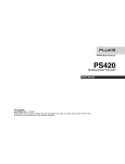
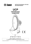
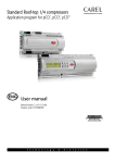
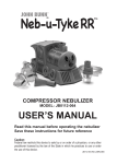
1
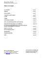
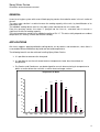
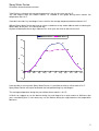
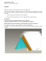
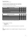
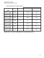
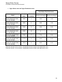
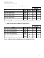
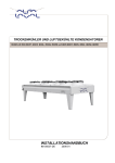
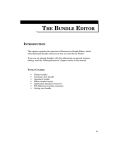
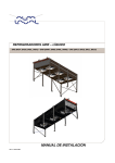
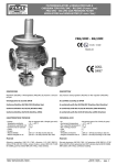
SPRAY WATER DEVICE
Alfagreen Vtype - Alfagreen Dual - AlfaBlue Dual
User Manual
Spray Water Device
Installation and maintenance manual
Table of contents
TO THE USER
page 3
GENERAL
page 4
APPLICATIONS
page 4
TRANSPORT AND STORAGE
page 6
LAYOUT
page 7
THEORY
page 10
FUNCTIONALITY RANGE
page 12
USE CAS CONSIDERING SPRAY WATER DEVICE
page 14
WORKING PRESSURE AND FLOW CONDITION
Spage 18
SETTING PRESSURE AND WATER FLOW RATE IN CASE OF
SPECIAL ENVIRONMENTAL CONDITION
page 21
QUALITY OF WATER
page 26
SERVICE INSTRUCTIONS
page 26
SPARE PARTS
page 28
TROUBLESHOOTING
page 30
NOTE
page 30
How to contact Alfa Laval
The contact information for each country
is constantly updated in our website.
Visit Alfalaval site to get this information.
THE TECHNICAL INFORMATION
SUPPLIED AND OTHER MINOR
CHANGES CAN BE MODIFIED
WITHOUT NOTIFICATION.
2
Spray Water Device
Installation and maintenance manual
TO THE USER
Dear User,
this instruction manual is intended to be your permanent guide for the different situations you may
encounter when using this equipment.
Alfa Laval recommends you to study it carefully, and mainly, to make it available for the personnel
who normally install, operate and maintain the equipment.
This manual will be useless if cannot be reached by the personnel who may need it.
In the unlikely case that you may have some problem not contemplated in this manual, don’t hesitate
to contact the closest Alfa Laval’s representative.
We can offer you our help wherever you may be located.
NOTE
The manufacturer will not be held liable in any way and the product warranty no longer is valid
if these instructions are not observed or the units are not used correctly.
System Warranty:
This equipment is designed to operate properly when installed in accordance with accepted industry
standards. Failure to meet the following conditions may result in voiding the system warranty:
Water circuit, valves or accessories must be installed following industry standards for good
piping practices.
Set fluid flow and pressure of water circuit in accordance with what is described in this manual.
Do not set the device to work over 12 bar.
Use only water treated as described in this manual.
Don’t use this kit for more than 400 hours per year.
Don’t walk on pipes or supports.
Factory installed layout must not be changed without written Alfa Laval’s approval.
ATTENTION!
The connections require qualified installers to complete the liquids circuits.
Do not perform any installation or maintenance operations without having disconnected the
power supply.
3
Spray Water Device
Installation and maintenance manual
GENERAL
It consists of a pipe system with several fitted spraying nozzles that nebulize water in the air suction of
the coil.
The spray water solution is used to increase the cooling capacity of the units, by humidification of air
around the coil.
The adiabatic cooling device consists of a pipe system mounted on the air suction side.
From the spraying nozzles the water is sprayed into the inlet air, saturated inlet air causes a
significant increase of cooling capacity.
The inlet temperature could sink by adiabatic cooling of 5-6 °C. This data strictly depends on ambient
temperature, air velocity, airflow and relative humidity.
APPLICATIONS
Alfa Laval suggests applying adiabatic cooling device, on dry coolers and condensers, when there is
a reasonable difference between dry bulb and wet bulb temperatures.
The following benefits can be achieved installing Spray Water Device:
It is possible to overcome the heat peak.
It is possible to use the unit to cool water at temperatures lower than the ambient air
temperature.
Dry-Coolers and Condensers can be designed for a much lower entering air temperature to
obtain a smaller dimension unit with a smaller heat exchanger surface.
Temperature in Berlin
20
18
18
18
17
16
14
14
13
°C
12
10
9
8
8
6
4
4
3
2
1
0
0
Jan
-1
Feb
Mar
Apr
May
Jun
Jul
Aug
Sep
Oct
Nov
Dec
4
Spray Water Device
Installation and maintenance manual
Take Berlin as example: the average temperature in the city last year was 8.6°C.
July and August were the hottest months, as showed in the graph during these months the
temperature was 18°C.
If we don’t consider July and August in our statistic, the average temperature decreased to 6.8°C.
Without Spray Water Device we have to select a condenser or dry cooler able to work also during the
hottest days of the year: 18°C during the day.
Anyhow, knowing that these days represent 4% of all year, we have to oversize the unit.
Whitout Device
With Device
20
18
18
14
14
17
15
13
14
13
10
9
°C
8
5
4
3
1
0
0
-1
Jan
Feb
Mar
Apr
May
Jun
Jul
Aug
Sep
Oct
Nov
Dec
-5
If we consider a new unit with Spray Water Device, it’s possible to select a unit to work at 14°C.
Spray Water Device will help to overcome the heat peak during July and August.
The average temperature during the year without these months is 6.8°C.
In Berlin we suggest to use the device during July and August for a total amount of 360 hours per
year, considering that it’s not necessary use the device during the night because the temperature
decrease.
5
Spray Water Device
Installation and maintenance manual
TRANSPORT AND STORAGE
Kit Spray Water is delivered mounted for Alfagreen Vtype and AlfaBlue models.
If the equipment has to be stored before its installation (one or more months) it is convenient to take
the following precautions:
Leave the equipment in its packing.
Store it indoors, in a room with adequate conditions: temperature (15 to 25 º C), humidity
( 50 to 70 % ) and environment without corrosive liquids or vapors.
ATTENTION!
The condition of the unit should be verified at the moment of reception, check for shock marks
or cracks, which could cause damage to the equipment.
In case of damages during transportation, the transportation company should be informed
immediately, in writing in the Document of Delivery.
“It means that if the receiver accepts the goods (stamps and signs the document)
without any note of non-conformity, the forwarder is not responsible for missing packages or
damaged goods.
We strongly recommend the customer to evidence damaged or missing goods on
the full set of this document at the arrival of the goods.
With a copy of it by e-mail in your hands, we can speed up corrective actions
towards the forwarder and ask for insurance reimbursement.
Be careful, we can act only if we sell in DDU or DDP final destination basis, i.e. our
recommended delivery terms.
For ex-works shipments the customer has to act directly with forwarder in
charged by himself as per INCOTERMS2000 rules.”
Then, Alfa Laval or one of its agents should be informed regarding the damage on the
equipment.
The Client should complete a written report including photographs concerning each relevant
damage.
6
Spray Water Device
Installation and maintenance manual
LAYOUT
Follow the instructions of unit installation manual and remember that:
Not all the water sprayed will evaporate; therefore any surplus water must be drained or recovered.
Alfa Laval doesn’t provide a drain pan because the layout could change depending on customer
installation.
Leave the space to connect the kit to the main pipeline.
Do not install the kit where there is wind, as reported on unit instruction manual.
ATTENTION!
This device has been developed to avoid the risk of Legionella.
If you want to provide a tray to recover not evaporated water remember to:
DO NOT promote water accumulation to avoid the growth and spread of Legionella.
On V-type the nozzle angle is set on 10 degrees on vertical (drawing below).
This angle assures the best performance in absence of wind and humidity-temperature average
conditions.
7
Spray Water Device
Installation and maintenance manual
On Dual the nozzle angle is set on 15 degrees on horizontal (drawing below).
This angle assures the best performance in absence of wind and humidity-temperature average
conditions; both in vertical and horizontal unit installation.
NOTE
Before installing and starting up the Spray Water Device read this paragraph carefully.
Spray Water Device efficiency is influenced by:
Relative humidity
Ambient temperature
Fans motor airflow
Wind
The correlation between relative humidity and water absorption degree of efficiency is not linear.
For example:
If relative humidity is 90% the air is almost saturated; using Spray Water Device an
abnormal dipping will be noted. It’s because the air is not able to accept additional water
inside. It’s not necessary using the device.
If relative humidity is 30% the device is absolutely necessary, the charge of water in the
air has to be increased; the air will well accept nebulized water because it’s far from
saturation point.
8
Spray Water Device
Installation and maintenance manual
If the ambient temperature increases, also the water needed to saturate the air will increase. Take a
look to psychromeytric chart on chapter “theory” to better understand.
Trendline of water necessity at differents U.R.
100,0
90,0
80,0
U.R. %
70,0
60,0
40°C
50,0
25°C
40,0
30,0
20,0
20
30
40
50
60
70
80
90
100
110
l/h
For example, over a graph obtained by experimental test, which show the correlation between relative
humidity, temperature and water necessity for humidification, as described above.
The fan motor airflow is necessary to:
Intake the saturate air into the coil.
Increase nebulization efficiency thanks to turbulence created.
If the fan motor rpm decrease the device efficiency will decrease too.
In presence of light wind there are two opposite effects to evaluate:
Wind favourite air circulation increasing unit performance, this is positive.
Unfortunately light wind perturb droplet trajectory, also creating dipping; this is negative.
NOTE
Heavy wind is always negative, check unit installation manual to deeply understand reasons
and solutions.
Anyhow, Spray Water Device will not function in the correct way in presence of heavy wind.
9
Spray Water Device
Installation and maintenance manual
THEORY
The adiabatic saturation temperature is a specific temperature value at which water by adiabatic
evaporating brings the air itself to a saturation point; this then cools the water turning the temperature
towards the wet bulb temperature.
The physical phenomenon of adiabatic saturation is obtained by using an adiabatic vaporizing
system. The suction air on the water cooler collides with a very fine water particle mist obtained with
custom built spray nozzles fitted in order to create a complete and uniform saturation of the entering
air.
For these reasons nozzles are not oriented on coil, scope of Spray Water Device is humidifies the air
around the coil.
The psychometric chart
To explain how to calculate the adiabatic saturation temperature it’s necessary to introduce the
psychometric chart.
The psychometric chart represents the state of a given atmosphere by a point, which gives the drybulb, wet-bulb, relative humidity, specific volume and saturation temperature of the atmosphere.
Saturation humidity line:
Absolute humidity (AH) is the vapor content of air, given
in grams of water vapour per kg of air, i.e. g/kg. Air at a
given temperature and pressure can support only a certain
amount of moisture and no more. This is referred to as the
saturation humidity (SH). If this is plotted on a graph
against the dry bulb (air) temperature (DBT), we have the
basis of the psychromeytric chart and we get what is called
the saturation humidity line.
Relative humidity line:
Relative humidity (RH) is an expression of the moisture
content of a given atmosphere as a percentage of the
saturation humidity at the same temperature:
RH = 100 x AH/SH (%)
Relative humidity lines are plotted on the psychrometric
chart by halving each SH ordinate to obtain the 50% curve,
and further proportionate subdivision gives any
intermediated RH curve.
10
Spray Water Device
Installation and maintenance manual
Wet bulb temperature lines:
Wet bulb temperature (WBT) is measured by a hygrometer
(or psychrometer). This consists of two thermometers, one
measuring the DBT, the other having its bulb enclosed in a
wet wick. 'Web bulb depression' is noted as the difference in
the temperatures between the wet wick thermometer and the
DBT. The difference happens as the wet wick thermometer is
cooled down by the evaporation on the wick.
The amount of evaporation is a direct indication of the
moisture carrying capacity of the atmospheric air at that temperature and that lowers the WBT.
When the air is saturated, there is no evaporation, thus the DBT and WBT readings are identical,
and the depression is zero. In this way, the 'status point' is determined at the intersection of the
vertical DBT line and the sloping WBT line of the psychrometric chart.
Enthalpy lines:
Enthalpy (E) is the heat content of unit mass of the
atmosphere, in kJ/kg, relative to the heat content of 0°C
dry air. It was omitted from the psychromteric chart
shown above to avoid confusion which a third set of lines
will cause. The enthalpy lines would almost, but not quite,
coincides with the WBT lines. To avoid the confusion in
representing it, the enthalpy scale is given at the
perimeter of the chart and can be read by using a straight
edge.
For air condition P the enthalpy is read at point A.
The sensible heat component can be read at point B,
corresponding to the enthalpy of dry air at the same temperature. The remainder, i.e., A - B, is the
latent heat content.
The psychometric processes
A point on the chart, known as the status point, represents the state of a given atmosphere. If any two
of the three commonly available characteristics DBT, WBT and RH are known, the others can be read
from the chart.
Adiabatic saturation, can be represented by the movement of this status point in the following ways:
Adiabatic saturation:
If moisture is evaporated into an air volume without any
heat input or removal (this is the meaning of the term
'adiabatic'), the latent heat of evaporation is taken from
the atmosphere. The sensible heat content - thus the
DBT - is reduced, but the latent heat content is increased.
The status point moves up and to the left, along a WBT
line. This is the process involved in evaporative cooling.
11
Spray Water Device
Installation and maintenance manual
FUNCTIONALITY RANGE
Spray Water Device has been designed to properly work on various sets of external temperature and
relative humidity:
T air °C
25 ÷ 40
Relative Humidity %
30 ÷ 60
NOTE
If the unit has to work outside of this range, please contact Alfa Laval Heat Air Exchanger
Product Center to obtain an accurate Device design.
Example of theoretical calculation
Suppose that T ambient (external air) is 25°C / 50 % Ur (Point A).
The corresponding humidity ratio is 10 g/Kg of dry air.
From the point A, following the corresponding line at constant enthalpy, on saturation line we set Point
B; the corresponding humidity ratio is 13 g/Kg of dry air.
Humidity
Ratio
g/Kg
Saturation line
50% Relative Humidity
B
13 g/Kg
A
DBT °C
T=17°C
10 g/Kg
T=25°C
The air after the treatment should be at 17°C, but the humidification efficiency never is 100%.
12
Spray Water Device
Installation and maintenance manual
The humidification efficiency must be considered of 70%.
For this the length of line AC is the 70% of line AB: AC = 0.7*AB
Humidity
Ratio
g/Kg
Saturation line
50% Relative Humidity
C
A
DBT °C
T=20°C
10 g/Kg
T=25°C
Finally the inlet temperature before coil is 20°C.
To find the water flow follows the example:
∆X= (13-10)= 3 g/kg dry air
The airflow rate can be found with Palladio, suppose a total amount of 1000 m³/h.
M=1000m³/h x 1.2 kg/m³=1200 kg/h
The necessary amount of water to humidify the air is:
Mw = M x ∆X = 1200 kg/h x 3 g/kg = 3600 g/h = 3.6 l/hour
Every hour you must nebulize on the air 3.6 l of water to obtain an efficiency of 80%.
NOTE
Calculation based on psychometric chart is affected from a huge number of environment
variables, for this reasons Spray Water Device should be set considering surrounding
conditions.
13
Spray Water Device
Installation and maintenance manual
USE CAS CONSIDERING SPRAY WATER DEVICE
Suppose the air conditions:
Temperature= 40°C
Relative Humidity= 60%
If you need 1200kW to cool a fluid (Ethylen Glycol 35%) from 60°C to 45°C, you should select in this
way:
Model
Required Capacity
Margin
Length
Height
Depth
Standard Unit Weight
1 x VDDT907C
1200,00
2.1
9490
2210
2230
3209
kW
%
mm
mm
mm
kg
Fan data (per single model)
Air Flow Rate: High
Number of Fans
Fan Diameter
Rotation Speed
Noise LWA/LPA (10,0 m)
Power Consumption Op/Nom
Voltage
Nominal current
420000
14
910
890
100 / 67
50400
400(D)
100.8
m3/h
mm
1/min
dB(A)
W
V
A
14
Spray Water Device
Installation and maintenance manual
Considering that the air reach 40°C only during the summer, using a Spray Water Device you can
select a unit smaller and cheaper.
In the next chapter there are some table which indicate how choice the device; below it’s perform an
example.
Using the Spray Water Calculation File present in Sally (see picture), at 40°C and 50% of relative
humidity (point A), the corresponding humidity ratio is 24,359 g/Kg of dry air.
15
Spray Water Device
Installation and maintenance manual
From the point A, following the corresponding line at constant enthalpy, on saturation line
we set point B; the corresponding humidity ratio is 27,146 g/Kg of dry air.
The humidification efficiency must be considered of 70%.
For this the final temperature inlet temperature before coil is 33,48°C, it has been rescue 6.5°C.
The new air conditions are:
Temperature= 40-6.5°C = 33.5°C
Relative Humidity ~ 100%
Selecting the unit with the new condition you need obtain:
Model
Required Capacity
Margin
Length
Height
Depth
Standard Unit Weight
1 x VDDT905B
1200,00
1.3
6870
2210
2230
2035
kW
%
mm
mm
mm
kg
Fan data (per single model)
Air Flow Rate: High
Number of Fans
Fan Diameter
Rotation Speed
Noise LWA/LPA (10,0 m)
Power Consumption Op/Nom
Voltage
Nominal current (*)
310000
10
910
890
99 / 66
36000
400(D)
72
m3/h
mm
1/min
dB(A)
W
V
A
16
Spray Water Device
Installation and maintenance manual
Relevant difference between the units selected:
Without Spray Water Device
Model
Length
Standard Unit Weight
Number of Fans
Power Consumption Op/Nom
Nominal current
1 x VDDT907C
9490 mm
3209 Kg
14
50400 W
100.8 A
With Spray Water Device
1 x VDDT905B
6870 mm
2035 Kg
10
36000 W
72.0 A
To evaluate by yourself water flow rate necessary in this condition are necessary:
Humidity ratio of point A: 24,359 g/Kg (using the calculation file).
Humidity ratio of point B: 27,146 g/Kg (using the calculation file).
The airflow rate of the second unit selected: 310000 m³/h (on CAS printout).
Air density at 40°C and 50% Relative Humidity: 1,1274 Kg/ m³ (from the calculation file)
The necessary amount of water to humidify the air is:
Mw = 1,8852 [m3/h].
NOTE
In case of particular surrounding conditions and low fan rotations speed, the air pressure drop
on coil could increase due to fine drops accumulation.
Alfa Laval strictly recommend to select and use an adequate fin spacing.
17
Spray Water Device
Installation and maintenance manual
STANDARD WORKING PRESSURE AND FLOW CONDITIONS
Alfa Laval provides three types of nozzle, as sum up below.
Model with electrical wiring D
VDDS / VDD6 / ACVS 800-910
VDDS / VDD6 / ACVL 800-910
VDDS / VDD6 / ACVQ 800-910-1000
VDDS / VDD6 / ACVR 800-910-1000
BCDT / BCDS / BDDT / BDDS / BNDT / BNDS 800-910
BCDL / BDDL / BNDL 800-910
BCDQ / BDDQ / BNDQ 800-910-1000
BCDR / BDDR / BNDR 800-910-1000
Model with electrical wiring Y
VDDS / VDD6 / ACVS 800-910
VDDS / VDD6 / ACVL 800-910
VDDS / VDD6 / ACVQ 800-910-1000
VDDS / VDD6 / ACVR 800-910-1000
BCDT / BCDS / BDDT / BDDS / BNDT / BNDS 800-910
BCDL / BDDL / BNDL 800-910
BCDQ / BDDQ / BNDQ 800-910-1000
BCDR / BDDR / BNDR 800-910-1000
Nozzle
type I
Nozzle
type II
Nozzle
type III
X
X
X
X
X
X
X
X
Nozzle
type II
Nozzle
type III
Nozzle
type III
(**)
X
X
X
X
X
X
X (**)
X (**)
(**) decrease the water flow pressure of 50%, according to the airflow rate.
The nozzle is coupled to a unit cosidering:
• Module surface.
• Average airflow rate.
• Unit layout.
The nozzle proposed, delivered as standard realize the best performance in standard condition.
Note
If the working conditions are out of standard it’s possible to interchange the nozzle type
mounted.
18
Spray Water Device
Installation and maintenance manual
Vtype Standard noise and Vtype Low noise
Total Water Flow Inlet (l/min)
Model
VDD S/T/L 802/902
VDD6 S/T/L 802/902
ACV S/T/L 802/902
VDD S/T/L 803/903
VDD6 S/T/L 803/903
ACV S/T/L 803/903
VDD S/T/L 804/904
VDD6 S/T/L 804/904
ACV S/T/L 804/904
VDD S/T/L 805/905
VDD6 S/T/L 805/905
ACV S/T/L 805/905
VDD S/T/L 806/906
VDD6 S/T/L 806/906
ACV S/T/L 806/906
VDD S/T/L 807/907
VDD6 S/T/L 807/907
ACV S/T/L 807/907
VDD S/T/L 808/908
VDD6 S/T/L 808/908
ACV S/T/L 808/908
Length
Number
(mm)
of nozzles
Electrical wiring D
Electrical wiring Y
2620
4
5.02
2.04
3930
6
7.08
3.06
5240
8
10.04
4.08
6550
10
13
6
7860
12
15.06
7.02
9170
14
18.02
8.04
10480
16
20.08
9.06
Electrical wiring D: Every nozzle is designed to work at 2.5bar and nebulize 1.3 l/min.
Electrical wiring Y: Every nozzle is designed to work at 2.5bar and nebulize 0.6 l/min.
19
Spray Water Device
Installation and maintenance manual
Vtype Quiet noise and Vtype Residential noise
Total Water Flow Inlet (l/min)
Model
VDD Q/R 802/902/1002
VDD6 Q/R802/902/1002
ACV Q/R 802/902
VDD Q/R 803/903/1003
VDD6 Q/R803/903/1003
ACV Q/R 803/903
VDD Q/R 804/904/1004
VDD6 Q/R804/904/1004
ACV Q/R 804/904
VDD Q/R 805/905/1005
VDD6 Q/R805/905/1005
ACV Q/R 805/905
VDD Q/R 806/906/1006
VDD6 Q/R 806/906/1006
ACV Q/R 806/906
VDD Q/R 807/907/1007
VDD6 Q/R 807/907/1007
ACV Q/R 807/907
VDD Q/R 808/908/1008
VDD6 Q/R 808/908/1008
ACV Q/R 808/908
Length
Number
(mm)
of nozzles
2620
Electrical wiring D
Electrical wiring Y
4
2.04
1.02
3930
6
3.06
1.08
5240
8
4.08
2.04
6550
10
6
3
7860
12
7.02
3.06
9170
14
8.04
4.02
10480
16
9.06
4.08
Electrical wiring D: Every nozzle is designed to work at 2.5bar and nebulize 0.6 l/min.
Electrical wiring Y: Every nozzle is designed to work at 2.5bar and nebulize 0.3 l/min.
20
Spray Water Device
Installation and maintenance manual
Double Row Standard noise and Double Row Low noise
Model
BCDT / BCDS / BDDT / BDDS / BNDT / BNDS 802/902
BCDL / BDDL / BNDL 802/902
BCDT / BCDS / BDDT / BDDS / BNDT / BNDS 803/903
BCDL / BDDL / BNDL 803/903
BCDT / BCDS / BDDT / BDDS / BNDT / BNDS 804/904
BCDL / BDDL / BNDL 804/904
BCDT / BCDS / BDDT / BDDS / BNDT / BNDS 805/905
BCDL / BDDL / BNDL 805/905
BCDT / BCDS / BDDT / BDDS / BNDT / BNDS 806
BCDL / BDDL / BNDL 806
Length
(mm)
3500
4200
5250
6300
7000
8400
8750
10500
Number
of nozzles
10500
Total Water Flow
Inlet (l/min)
Electrical Electrical
wiring D
wiring Y
8
4.8
2.4
12
7.2
3.6
16
9.6
4.8
20
12
6
24
14.4
7.2
Electrical wiring D: Every nozzle is designed to work at 2.5bar and nebulize 0.6 l/min.
Electrical wiring Y: Every nozzle is designed to work at 2.5bar and nebulize 0.3 l/min.
Double Row Quiet noise and Double Row Residential noise
Model
BCDQ / BDDQ / BNDQ 802/902/1002
BCDR / BDDR / BNDR 802/902/1002
BCDQ / BDDQ / BNDQ 803/903/1003
BCDR / BDDR / BNDR 803/903/1003
BCDQ / BDDQ / BNDQ 804/904/1004
BCDR / BDDR / BNDR 804/904/1004
BCDQ / BDDQ / BNDQ 805/905/1005
BCDR / BDDR / BNDR 805/905/1005
BCDQ / BDDQ / BNDQ 806
BCDR / BDDR / BNDR 806
Length
(mm)
3500
4200
5250
6300
7000
8400
8750
10500
Number
of nozzles
10500
Total Water Flow
Inlet (l/min)
Electrical Electrical
wiring D
wiring Y
8
2.4
1.2
12
3.6
1.8
16
4.8
2.4
20
6
3
24
7.2
3.6
Electrical wiring D: Every nozzle is designed to work at 2.5bar and nebulize 0.3 l/min.
Electrical wiring Y: Every nozzle is designed to work at 1.5bar and nebulize 0.15 l/min.
21
Spray Water Device
Installation and maintenance manual
SETTING PRESSURE AND WATER FLOW RATE IN CASE OF
SPECIAL ENVIRONMENTAL CONDITION
In this section there are three graphs, each one show a pressure-flow correlation.
To set the Spray Water Device, if environmental condition is over the functionality range, use the
graph below. Use this graph type also when suggested in troubleshooting section.
Example: if the line water pressure is higher than 2.5÷3.0, the flow rate will be higher.
Thanks to these graphs it’ possible to predict Device efficiency.
Nozzle Type I pressure-flow selection chart
NOZZLE TYPE I
DO NOT SELECT PRESSURE
OVER THIS LIMITS
5
4,5
4
3,5
l/min
3
2,5
2
1,5
1
0,5
0
0
2
4
6
8
10
12
14
16
18
20
22
24
bar
This type of nozzle is mounted on:*
VDDS 800-910
VDDL 800-910
It assure an optimal air saturation with high airflow rate.
A large water spray cone allow to cover all the coil surface, especially where the air velocity is
maximum.
22
Spray Water Device
Installation and maintenance manual
Nozzle Type II pressure-flow selection chart
NOZZLE TYPE II
DO NOT SELECT PRESSURE
OVER THIS LIMITS
2,5
2,25
2
1,75
l/min
1,5
1,25
1
0,75
0,5
0,25
0
0
2
4
6
8
10
12
14
16
18
20
22
24
bar
This type of nozzle is mounted on:*
VDDQ 800-910-1000
VDDR 800-910-1000
BCDT BCDS BDDT BDDS BNDT BNDS 800-910
BCDL BDDL BNDL 800-910
It assure an optimal air saturation with lower airflow rate than previous model.
It’s suggested to use this type of nozzle on and VDDL 800 and VDDL 910 if the design temperature is
lower than 25°C and/or the relative humidity is higher than 60%.
In this way it’s possible to avoid the flooding risk, that could be effective in the upon weather
conditions.
23
Spray Water Device
Installation and maintenance manual
NozzleType III pressure-flow selection chart
NOZZLE TYPE III
DO NOT SELECT PRESSURE
OVER THIS LIMITS
0,8
0,7
0,6
l/min
0,5
0,4
0,3
0,2
0,1
0
0
2
4
6
8
10
12
14
16
18
20
22
24
bar
This type of nozzle is mounted on:*
DCDQ BCDQ BDDQ BNDQ 800-910-1000
DCDR BCDR BDDR BNDR 800-910-1000
It’s used to guarantee the best humidification efficiency, also with low airflow rate.
*on version with electrical wiring D
Note
Never set device to work over 12 bar.
Note
All types of nozzle can be fitted in the whole units range.
See Spare Parts section to know Alfa Laval code of nozzle Type I, Type II and Type III.
24
Spray Water Device
Installation and maintenance manual
Below a table to find a water density at design temperature and relative humidity.
Use these table to perform a calculation of water needed in case of abnormal weather conditions.
Temp
°C
20
20
20
20
21
21
21
21
22
22
22
22
23
23
23
23
24
24
24
24
25
25
25
25
26
26
26
26
27
27
27
27
28
28
28
28
U.R.
%
30
40
50
60
30
40
50
60
30
40
50
60
30
40
50
60
30
40
50
60
30
40
50
60
30
40
50
60
30
40
50
60
30
40
50
60
Dens
Kg/m³
1,2
1,2
1,2
1,2
1,2
1,2
1,19
1,19
1,19
1,19
1,19
1,19
1,19
1,19
1,19
1,18
1,18
1,18
1,18
1,18
1,18
1,18
1,18
1,18
1,18
1,17
1,17
1,17
1,17
1,17
1,17
1,17
1,17
1,17
1,16
1,16
Temp
°C
29
29
29
29
30
30
30
30
31
31
31
31
32
32
32
32
33
33
33
33
34
34
34
34
35
35
35
35
36
36
36
36
37
37
37
37
U.R.
%
30
40
50
60
30
40
50
60
30
40
50
60
30
40
50
60
30
40
50
60
30
40
50
60
30
40
50
60
30
40
50
60
30
40
50
60
Dens
Kg/m³
1,16
1,16
1,16
1,16
1,16
1,16
1,15
1,15
1,15
1,15
1,15
1,15
1,15
1,15
1,15
1,14
1,15
1,14
1,14
1,14
1,14
1,14
1,14
1,14
1,14
1,14
1,13
1,13
1,13
1,13
1,13
1,13
1,13
1,13
1,12
1,12
Temp
°C
38
38
38
38
39
39
39
39
40
40
40
40
41
41
41
41
42
42
42
42
43
43
43
43
44
44
44
44
45
45
45
45
U.R.
%
30
40
50
60
30
40
50
60
30
40
50
60
30
40
50
60
30
40
50
60
30
40
50
60
30
40
50
60
30
40
50
60
Dens
Kg/m³
1,13
1,12
1,12
1,12
1,12
1,12
1,12
1,11
1,12
1,11
1,11
1,11
1,11
1,11
1,11
1,1
1,11
1,11
1,1
1,1
1,11
1,1
1,1
1,09
1,1
1,1
1,09
1,09
1,1
1,09
1,09
1,09
ATTENTION!
Always check pressure and flow conditions, arranging it in case of environment conditions
change. Also see troubleshooting section.
25
Spray Water Device
Installation and maintenance manual
Below a psychrometric chart.
Use these table to perform a calculation of water needed in case of abnormal weather
conditions.
26
Spray Water Device
Installation and maintenance manual
QUALITY OF WATER
On this kit use only water characterized by:
PH: 6 ÷ 7
Hardness: 8 ÷ 12 °F (80 ÷ 120 ppm as CaCO3)
Using this kind of water, after 400 hours of use, there will not visible limestone deposit and calcium
layer on the coil.
Anyhow tube is made of Inox to avoid internal rust formations, also during the inactivity time.
Pipe is developed to be easy drainable, it’s possible to inclin from bends to collectors side.
Anyhow, assure to flux with air the pipeline during non operative time, to avoid freezing risk.
NOTE
If the utilization exceed 400 hours per year apply an suitable coil treatment (depending also on
surrounding conditions)
ATTENTION!
Always use a filter on pipeline to avoid deposit of dirt.
Flux the pipeline with air to complitely drain the water during inactivity period.
SERVICE INSTRUCTIONS
ATTENTION!
Before starting service operations make sure that the circuit is reliably switched off!
Trouble-free operation of Spray Water Device adiabatic system requires regular service to
check.
NOZZLE MAINTENANCE
The nozzles need regular maintenance with the scope of keeping the efficiency and avoid damages.
A first check after 5 hours of running and then every 100 hours is suggested.
27
Spray Water Device
Installation and maintenance manual
Common causes of spray nozzle problems:
Erosion. The gradual removal of material from the surfaces of the nozzle orifice and internal
flow passages causes them to become larger and/or distorted, which can affect flow, pressure,
and spray pattern.
Clogging. Unwanted dirt or other contaminants blocking the inside of the orifice can restrict
the flow and disturb spray pattern uniformity.
Caking. Over spraying, misting, or chemical buildup of material on the inside or outer edges of
the orifice from evaporation of liquid can leave a layer of dried solids and obstruct the orifice or
internal flow passages.
Temperature damage. Heat may have an adverse effect on nozzle materials not intended for
high-temperature applications.
Improper reassembly. Misaligned gaskets or other repositioning problems can result in
leakage as well as poor spray performance.
Accidental damage. Scratching through the use of improper tools during installation or
cleaning can cause inadvertent harm to an orifice.
PIPELINE MAINTENANCE
Verify that the circuit is not occluded, it can happen if the quality of water is not as requested before. A
first check after 10 hours of running and then every 200 hours is suggested.
DRAINAGE TO AVOID ICE FORMATIONS
If the ambient temperature is under zero remember to drain the pipeline, to avoid the formation of ice.
CLEANLINESS OF COIL
Follow the instruction manual of unit to clean the coil (clean at least two time per year to keep out the
limestone).
28
Spray Water Device
Installation and maintenance manual
SPARE PARTS
(for details see the RCPL)
A
B
C
E
D
ATTENTION!
Use only Alfa Laval original spares
29
Spray Water Device
Installation and maintenance manual
A Nozzle
B Split Eyeless Connectors
C Pipe Supporting Ring
D Rod
E Pipeline
See pages 18-20
Type I
Cod. 41002561
All Units
All Units
All Units
DCV_802_902_1002
DCV_803_903_1003
DCV_804_904_1004
DCV_805_905_1005
DCV_806_906_1006
DCV_807_907_1007
DCV_808_908_1008
DUAL_802
DUAL_803
DUAL_804
DUAL_805
DUAL_806
DUAL_902_1002
DUAL_903_1003
DUAL_904_1004
DUAL_905_1005
Type II
Cod. 41002560
Cod. 41002558
Type III
Cod. 41002559
Cod. 43007550
Cod. 43007551
Cod.
V9999883+
Cod.
V9999882+
Cod.
V9999883+
Cod.
V9999882+
Cod.
V9999882+
Cod.
V9999882+
Cod.
V9999883+
Cod.
V9999897+
Cod.
V9999896+
Cod.
V9999897+
Cod.
V9999896+
Cod.
V9999896+
Cod.
V9999893+
Cod.
V9999893+
Cod.
V9999893+
Cod.
V9999893+
Cod.
V9999879
Cod.
V9999879
Cod.
V9999878
Cod.
V9999879
Cod.
V9999878
Cod.
V9999895
Cod.
V9999895
Cod.
V9999894
Cod.
V9999892
Cod.
V9999891
Cod.
V9999891+
Cod.
V9999892
Below a list of pipe code with relative length.
Every pipe is provided with rapid connections for fast and easy mounting.
Code
Length
V9999878
3895 mm
V9999879
2585 mm
V9999882
4080 mm
V9999883
2770 mm
V9999884
4165 mm
V9999885
2065 mm
Code
Length
V9999886
4450 mm
V9999887
5215 mm
V9999888
3465 mm
V9999889
5500 mm
V9999890
3750 mm
V9999891
4165 mm
Code
Length
V9999892
2065 mm
V9999893
4450 mm
V9999894
5215 mm
V9999895
3465 mm
V9999896
5500 mm
V9999897
3750 mm
30
Spray Water Device
Installation and maintenance manual
TROUBLESHOOTING
Problem
No water from nozzles
No water from one nozzle
Possible Cause
Solution
No water inlet
Dirt on pipe section or nozzle
Check the connection
Check pipe or nozzle
Decrease the pressure
according with new
calculated water flow rate.
Check water pressure and
flow rate
Environmental conditions are changed
Water dripping
Wrong water pressure or flow rate
NOTE
Rev. 03: Added model AlfaBlue Condenser - AlfaBlue Dry Cooler – AlfaBlue Ammonia Condenser
Rev. 04: Delete old series, DCD – ACD – DCV. Sobstitute cod.43007520 with 43007550 and
cod.43007524 with 43007551 both in stainless steel material.
Sobstitute the Palladio selection with CAS selection.
Rev.05: Delete the E (Pipe Supporting Stirrup) component cod. 60626118.
Alfa Laval Spa Via delle Albere, 36040 Alonte (VI) – Italy
Tel. +39.0444.725411 – Fax+39.0444.725400
31