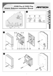
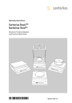
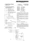
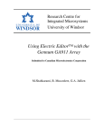
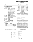
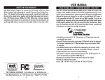
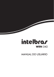
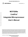
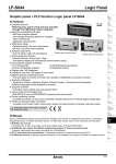
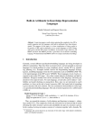
1
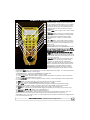
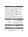
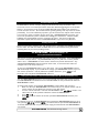
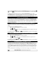
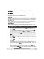
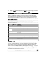
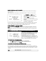
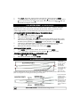
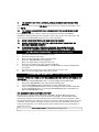
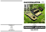
PRODIGY ADVANCE 2 New Prodigy Advance″ items have retained all the features of the standard Prodigy Advance system with the addition of F28 (28 loco functions) compatible. To operate the loco functions you must use the keys marked 0 – 9 as stated in the manual, functions 11 – 28 will require the SHIFT key to be pressed before the desired function number in full. As on all units the LCD screen will only display up to F12. Both Prodigy systems are fully compatible with each other but only when both walkabout and base unit have the PRODIGY ADVANCE ″ logo will the full 28 functions be accessible. In the event of either item not carrying this logo the system will default to the standard 20 functions. Up to twenty -five loco addresses can be held in the walkabout memory but if only two are entered it will default to one, if this happens a third loco address should be entered. This notice supersedes all other instructions in regards to this system GAUGEMASTER PRODIGY ADVANCE USER MANUAL AUTUMN 2005 - Version 1.2 - E & OE GAUGEMASTER Scenic Products “Model Railway Solutions” All these dioramas were built by Nick Duxfield (Sales Manager for GAUGEMASTER) using GAUGEMASTER scenic material Trees Scatters Flock Foliage Lichens Grasses Mod-roc Ballast Sea Foam Leaves Scenic Mats Cork Roll Underlay Track Pins THANK YOU FOR CHOOSING PRODIGY ADVANCE Here at GAUGEMASTER, we have been manufacturing model railway controllers for around 30 years and without being big-headed, feel that our reputation for top quality controllers is well-deserved and justified. In life, things evolve and technology offers us new opportunities to try things that were previously impossible or at least prohibitively difficult. Who’d have thought when we began making model railway controllers that in around 30 years time, almost all of us would own mobile telephones, digital cameras, personal computers and have over 200 TV channels to choose from via the medium of satellite broadcasting. And that’s before we even mention the internet - possibly the greatest and most accessible resource there is. That is not to say that older technology is no good, we know many photographers who prefer to use conventional film over digital - it’s just the new opportunities that technology offers that makes it so exciting and that is how we feel about DIGITAL COMMAND CONTROL. It’s the opportunity to run your railway, the way you want rather than within the constraints of traditional operation - a new perspective on the operation of model railways. PRODIGY ADVANCE is “Quality in Digital Control”. Imagine, for example - a diesel depot with an array of locomotives “on shed”. This layout is powered by PRODIGY ADVANCE. No doubt you will have a few questions. Q. A. Q. A. Q. A. Q. A. How do I physically drive my trains? On the WALKAROUND How many isolating sections are there? None. With DCC, you simply select your locomotive, drive it to where you want and then select another locomotive Where is my point control panel? There isn’t one. Everything you need is on your WALKAROUND. How do I separate my Up and Down Running Lines? No need. You drive the trains where you want on your layout You’ve noticed the capabilities of PRODIGY ADVANCE in the context of a small depot layout. Can you imagine the possibilities on a larger layout? You’re going to have a lot of fun. GAUGEMASTER - The UK Home of Prodigy Advance 3 YOUR PRODIGY ADVANCE SYSTEM Your Prodigy Advance DCC System includes the following: 1. Power Pack 2. Base Unit 3. Walkaround Controller with LCD screen 4. Leads for Power Pack and Controller PRODIGY ADVANCE - POWER SUPPLY AND BASE UNIT 10 1 9 8 2 3 7 4 6 5 1. Power supply – 15v DC at 3.5 amps. 2. WALKAROUND select switch – Used to select from “1 to 8 WALKAROUNDS” or “All WALKAROUNDS” (1-99). 3. “Factory use only” socket – For factory use only at this time and will be used for future upgrades. Do not insert foreign objects into this port. Inadvertently plugging a WALKAROUND into this port will not damage the system, although the WALKAROUND will not function. 4. WALKAROUND sockets (three) – Plug up to three WALKAROUNDS or use these ports to expand to a network of additional WALKAROUND extension plates around the layout. Up to 99 WALKAROUNDS can be used in a network. 5. Power on/off switch – Turns BASE UNIT power on/off. 6. Power light – Glows when system is on. 7. Link light – Flashes during transmission of program data from the WALKAROUND to the BASE UNIT. This lets you know the BASE UNITS is receiving and accepting data. The light remains off at all other times. 8. Cooling fan – Does not operate all the time and will only come on during times of heavy load on the layout. 9. Terminal plug output to main layout track and program track 10. 15v DC input from POWER PACK Note Prodigy Advance does not support NON-decoder equipped analogue locos. 4 GAUGEMASTER - The UK Home of Prodigy Advance PRODIGY ADVANCE - WALKAROUND 1 11 2 12 3 13 4 14 5 15 6 16 7 17 8 18 9 19 10 1. Function display – Large, easy to read LCD screen. Lets you monitor current loco address in use, functions in use for that address, fast clock display, loco speed and direction. Also displays all programming features in program mode and accessory decoder setup and programming. 2. Select LOCO button – Used to select a loco or consist address. 3. DBL HEAD button – Used to set up double heading/ multiple unit operation (also known as Consists), add locos to double heads and clear double heading. 4. Function buttons – Allow you to select decoder functions. 5. -1 or DEL button – Dual function button that allows you to delete locos from the stack; and when running a current loco, allows you to Incrementally decrease the loco speed. A stack is a group of locos stored in your WALKAROUND memory. Each WALKAROUND can store up to 25 different loco addresses in its stack. Tap or press the -1 button quickly to decrease the loco speed. Holding the button for more than 2 seconds will delete the current loco from the stack. 6. TIME button – Allows you to view fast clock time while running current loco address. Press again to shut off time display. (The time is stored in the base unit, all Cabs see the same time). 7. SPD STEP button – Used to synchronize the knob to programmed speed step (14/28/128) of decoder currently in use. Prodigy Advance Automatically programs all decoders to 28/128 speed steps. Speed steps are incremental steps that the decoder takes to go from 0 m.p.h. to full speed with the use of the WALKAROUND control knob. The higher number of speed steps programmed into the decoder, the finer the speed control. 8. Emergency STOP button – Press this button for 2 seconds to stop the Main Track output. To restore the Main Track output, press and hold STOP for 2 seconds again. 9. WALKAROUND lead – Connects the WALKAROUND to the BASE UNIT 10. LCD Screen (see Function display feature number 1 above) 11. Select ROUTE button – Used to set Routes through pointwork when points are powered by accessory decoders and accessing the programmed Route in run mode. 12. Select ACCESSORY button – Used to program accessory decoders as well as selecting accessory decoders when in run mode. 13. PROG button – Used to program locos, accessory decoders and read values in decoders. 14. SYS button – Used to change WALKAROUND system parameters or settings. 15. +1 or ENTER button – Dual function button that allows you to lock in selections and information during programming process. When running a current loco, allows you to incrementally increase the loco speed. 16. RECALL button – Allows you to scroll through the loco stack to select a loco address to run. 17. SHIFT button – Used to access decoder functions higher than function #9. For example, if you want to access function 12, press SHIFT and 2 button to turn on/off function #12. 18. DIRECTION button – Changes direction of current loco address. 19. WALKAROUND controller knob – Used to adjust the speed of the current loco. When used in the “Yard” Cab mode, it can also reverse the direction of the current loco. The controller knob may be referred to as a potentiometer, pot or as an encoder - these are names of the parts used to make a controller knob. Prodigy Advance uses an encoder instead of a pot. GAUGEMASTER - The UK Home of Prodigy Advance 5 TABLE OF CONTENTS 1 GETTING STARTED 1.1 Introduction 1.2 DCC Basic Background 1.3 Specifications & Features 1.4 System Menu Summary Chart 2 OPERATION 2.1 Quick Start Connecting to your Layout Running a Locomotive Controlling Accessory Functions Recalling Locomotives Deleting Locomotives Emergency Stopping Speed Steps Yard Mode On/Off Fast Clock Cooling Fan Overload and Short Circuit Shutting Down the Unit 2.2 WALKAROUND Set-up Setting WALKAROUND Addresses Setting the Total Number of Operational WALKAROUNDS (WALKAROUND #1) Adding More than 3 WALKAROUNDS Setting Last WALKAROUND Allowed to Program Locomotives on the Main Track (WALKAROUND #1) Setting Last WALKAROUND Allowed to Program Locomotives on the Program Track (WALKAROUND #1) 2.3 Programming Decoders 2.4 Programming Locomotives on the Program Track 2.5 Programming Locomotives on the Main Track 2.6 Reading Locomotive’s Decoder Values on the Program Track 2.7 Configuration Variables - (CV’s) Most Commonly Used CV’s CV29 2.8 Consisting (Also Known as DOUBLE HEADING) Advanced Consisting Programming Advanced Consists Running Advanced Consists Clearing Advanced Consists Universal (Old Style) Consisting Programming Universal (Old Style) Consists Running Universal (Old Style) Consists Clearing Universal (Old Style) Consists 2.9 Fast Clock Setting Fast Clock (WALKAROUND #1) Setting Time (WALKAROUND #1) Setting Time Ratio (WALKAROUND #1) Setting AM/PM or 24 Hour Time (WALKAROUND #1) 2.10 Reverse Loop 2.11 Accessory Decoders Programming Accessory Decoders with CV #513 Selecting Accessory Decoders 2.12 Accessory Routes Setting Accessory Decoder Routes (WALKAROUND #1) Running Accessory Routes Clearing Accessory Routes 2.13 Points 3. 4. 5. 6. 6 TROUBLE SHOOTING 3.1 General Trouble Shooting 3.2 Checklist for General Problems 3.3 More on Programming Locomotive Addresses on the Program or Main Track & Decoder Read Back SERVICE AND SUPPORT GLOSSARY THE GAUGEMASTER PRODUCT RANGE GAUGEMASTER - The UK Home of Prodigy Advance 1. GETTING STARTED - AN INTRODUCTION 1 Thank you for buying the PRODIGY ADVANCE DCC (Digital Command Control) system. This is one of the most easy to use DCC systems available and has been designed by the Model Rectifier Corporation in America. Rather than re-invent the wheel, we at GAUGEMASTER were soon convinced that PRODIGY ADVANCE best met the needs of the UK modeller. Very soon you will realise you have chosen the right system. PRODIGY ADVANCE comes with a BASE UNIT, a POWER PACK and a WALKAROUND controller which will enhance the enjoyment of your Model Railway for many years to come. This system has been designed to give you advanced, reliable and easy to use DCC control with 9,999 addresses available and use of up to 99 WALKAROUNDS, this is a system that caters for almost any model railway, from the smallest of shunting layouts to the biggest main line model railways. You will notice that there are brief bullet point style instructions on the back of the WALKAROUND unit. These have been designed more as a reminder than as complete instructions. Please read these instructions fully to understand and enjoy all the features of PRODIGY ADVANCE DCC BASIC BACKGROUND INFORMATION DCC stands for DIGITAL COMMAND CONTROL. A typical system consists of a BASE UNIT that sends DCC commands to your layout, and DCC decoders installed in your locomotives which receive the DCC commands. Each decoder-equipped locomotive has it’s own address. Each decoder receives DCC commands but only follows those commands matching it’s own address. It really is that simple - no more cab control, no more isolating sections and much less wiring. With DCC, you can run different locomotives at different speeds anywhere on your layout and all on the same track if you wish! You can turn the locomotive’s headlight on and off and even activate sounds if your locomotives are suitably equipped. By reading this manual fully you will soon have a good grasp of DCC control and will be able to enjoy the many benefits of the PRODIGY ADVANCE system. Please note that PRODIGY ADVANCE does not support NON-decoder fitted or analogue locomotives. Some DCC systems do offer this facility but experience has taught us that this practice dramatically slows the response time of DCC systems. This was unacceptable to us and is why this facility is no longer offered. SPECIFICATIONS AND FEATURES INPUT—15-16v DC 3.5 amps OUTPUT - DCC Signal with 14.5v amplitude for OO/HO & N Scales MAXIMUM CURRENT - 3.5 amps MAXIMUM NUMBER OF WALKAROUNDS - up to 99 ADDRESS CAPABILITY - 2 Digit (1-127) or 4 digit (1-9999) SPEED STEPS - 14/28/128 ACCESSORY FUNCTIONS - 20 (F0 to F19) ADVANCED AND UNIVERSAL DOUBLE HEADING OR CONSISTING PROGRAMME LOCOMOTIVE ON PROGRAM TRACK PROGRAMME LOCOMOTIVE ON MAIN TRACK READ LOCOMOTIVE ON MAIN TRACK GAUGEMASTER - The UK Home of Prodigy Advance 7 SYSTEM MENU SUMMARY CHART Most functions are initiated by pressing their associated keys. However, there are ten functions activated by pressing the SYS key followed by a numeric key (0-9). The following table summarises these ten functions. Information about each function is found later on in this manual. KEYS FUNCTION SYS + 0 Clear Routes SYS + 1 Set Time SYS + 2 Set Time Ratio SYS + 3 Yard on/off SYS + 4 Set Time Mode (am/pm/24hr) SYS + 5 Set Routes SYS + 6 View Your WALKAROUND Address SYS + 7 Set Last WALKAROUND allowed to program locos on the main track SYS + 8 Set Last WALKAROUND allowed to program locos on the program track SYS + 9 Set total number of operational WALKAROUNDS 2.1 OPERATION - QUICK START Connecting PRODIGY ADVANCE to your layout Follow the diagram to connect the BASE UNIT to your layout. 1. Plug the POWER SUPPLY into the BASE UNIT. 2. Plug the AC lead into your wall socket. 3. Using a small flat-bladed screwdriver, attach two wires (0.643mm or heavier) from your Main Track layout (one from each rail) to the terminals marked “Main Track” and two wires from your Program Track to the terminals marked “Programming Track”. 4. Plug one end of the cable into the WALKAROUND and the other into a “Controllers” socket on the BASE UNIT. Do not use the socket marked “Factory Use Only” as this is for potential future upgrades. 5. Double check all wiring and then turn the power switch on the BASE UNIT to the “On” position. The power light should be on and you are now ready to run your Decoder Equipped locomotives. 8 GAUGEMASTER - The UK Home of Prodigy Advance Running a Locomotive Firstly, turn the “Select Controller” switch on the BASE UNIT to “Ctlrs 1-8”. This will give you a faster response time. This is because the BASE UNIT will now only try to communicate with Controllers 1 to 8 and not 9 to 99. Naturally, this speeds things up a bit! To run a locomotive, you must first establish it’s address. Most decoders you will buy have a factory default address of #3. If you buy a decoder equipped locomotive, you may find that it’s running number or reference number is sometimes used. Consult your decoder or locomotive instructions to find out what it’s decoder address is. To select a locomotive, press the LOCO key on your WALKAROUND unit. Using the numeric keypad (0-9), enter the locomotive’s address and press ENTER. You have just selected your locomotive. The WALKAROUND controller will remember this address for later recall. Use the DIRECTION key to set the direction in which you want your locomotive to travel. Turn the control knob slowly to increase the speed of the locomotive. Your selected locomotive will begin moving. Alternatively, you can tap +1 or –1 to adjust the speed. DO NOT, however, hold down the –1 key as this is also the DEL key and will delete the locomotive’s address from the WALKAROUND and you will have to select it again. To toggle the headlight (F0) on and off, press 0. If you are using more than one WALKAROUND, you may notice a blinking locomotive address on the screen. This indicates that another WALKAROUND is also controlling that locomotive. However, you will find that the locomotive will not move as you would expect it to as it will be receiving commands from at least two different sources! Other operators should relinquish control of the locomotive so you can control it properly from your WALKAROUND. Controlling Accessory Functions To control accessory functions F1-F9, press 1-9. To control F10-F19, press SHIFT then 0-9. When F1-F12 are on, F1-F12 will be displayed on the LCD. F13-F19 will not be displayed. Therefore the snapshot of an LCD WALKABOUT display on the left shows us that the current locomotive is 3802, running in reverse at a speed of 102 with accessory functions F1 and F11 being on. Recalling Locomotives To call up previous locomotives stored in the memory, press RECALL. You can recall up to 25 locomotives using this feature. Please note that although the WALKAROUND can store up to 25 locomotives, if it is unplugged from the BASE UNIT, it will only retain the last 4 locomotives used. Deleting Locomotives The WALKAROUND can store up to 25 locomotives. If you select a new locomotive when the WALKAROUND is full, the new locomotive will replace the current locomotive which will be GAUGEMASTER - The UK Home of Prodigy Advance 9 lost. To prevent this, we recommend that you recall unused locomotives and delete them by pressing and holding DEL for 2 seconds. This then creates capacity to store new locomotives. Emergency Stopping For emergency stopping of the current locomotive, press STOP. Pressing and holding STOP for 2 seconds will stop the Main Track output. The 2 lights on the BASE UNIT will blink. To restore the Main Track output, press and hold STOP for 2 seconds again. Speed Steps Speed steps are incremental steps the locomotive takes to go from 0 to top speed. There are 3 speed steps: 14, 28 and 128. The higher the speed step setting, the higher the number of different speeds on which the locomotive can operate. When you enter a new locomotive address (an address that has not been stored in the WALKABOUT memory), PRODIGY ADVANCE will set 28 speed steps as the default setting for that address. In order to make the most of the performance of your locomotive, you may need to change the speed steps setting to match those of the decoder inside the locomotive. To select other speed steps settings press SPD STEP repeatedly until you see your desired speed steps setting and then press ENTER. The selected speed steps setting will apply only to that address. Please remember that use of the SPD STEP button will NOT alter the speed step originally programmed into the decoder. It only matches the control knob to the decoder. Yard Mode On/Off To toggle the Yard Mode feature on or off, press SYS and 3. In standard control mode, the control knob only controls locomotive speed. When the Yard Mode feature is on, with “Yard” displayed on the LCD screen on the WALKAROUND, the control knob will control the speed and direction of the locomotives - like some existing analogue controllers where 12 o’clock is Stop with directional movement either side. Fast Clock To view the Fast Clock, press TIME. The time will replace the address display on the LCD. You can still run the current locomotive while the time is displayed. To return to the standard locomotive address display, press TIME again. The time information is stored in the BASE UNIT and transmitted to the WALKAROUND with each attached WALKAROUND displaying the same time. The diagram to your left shows a time of 8.02am with the current locomotive moving forward at a speed of 102. Cooling Fan The Cooling Fan does not operate all the time, only activating during heavy loads. 10 GAUGEMASTER - The UK Home of Prodigy Advance Overload and Short Circuit The BASE UNIT is rated at 3.5amps. Only you will know how many locomotives and accessories can be run on the layout at the same time without triggering the circuit breaker. If there is an overload or short circuit, the BASE UNIT will stop the Main Track output for 2 seconds and then resume. The fan will activate (spinning slowly) and may come on and off periodically. To resume satisfactory operation, you must remove the subject of the overload or short circuit. Using a separate 16v AC supply (eg, a GAUGEMASTER M1) to power your accessories optimises the power available for running your locomotives. Solenoid motors, buildings and coach lighting are heavy consumers of power. The Accessory Decoder instructions explain how to connect a GAUGEMASTER M1 to your Accessory Decoders. Shutting Down the Unit Please turn the power switch to the “Off” position before unplugging the POWER PACK from the AC outlet. This will then allow the BASE UNIT to store all current running information, including time, for your next operating session. 2.2 OPERATION - WALKAROUND SET UP Setting WALKAROUND ADDRESSES You can use up to 99 WALKAROUND units with the PRODIGY ADVANCE. Each WALKAROUND must have a unique address. Any WALKAROUND that you buy will have a factory default address of #1. WALKAROUND #1 is the master unit that can perform all functions. Any additional WALKAROUNDS will also become master units, so must have their addresses changed from #1 to unique addresses. To view your WALKAROUND address, press SYS and 6. The current WALKAROUND address will momentarily display. If you would like to change you WALKAROUND address, type in a new address (between 1 and 99) followed by ENTER. Otherwise, press ENTER to exit. Remember not to duplicate WALKAROUND addresses. Setting the Total Number of Operational WALKAROUNDS (Master WALKAROUND only) The more WALKAROUNDS that are in use at any one time, the slower the system responds from WALKAROUND to locomotive because the BASE UNIT can only communicate with one WALKAROUND at a time. To set the total number of operational WALKAROUNDS, please follow this procedure 1. Make sure that your WALKAROUND is the master unit (#1) as only the master unit can set the number of cabs allowed to operate on your DCC layout. 2. Turn the “Select Controller” switch on the BASE UNIT to the “ALL CTRLS” position. The switch must be in this position to limit the number of WALKAROUNDS. 3. Press SYS and 9 4. Using 0-9, enter the address of the last operational WALKAROUND and then press ENTER. For example, if you use 10 WALKAROUNDS and program the WALKAROUND addresses #1 to #10, pressing SYS, 9, 10 and then ENTER - you will set the last operational WALKAROUND to 10 and the BASE UNIT will not spend any time trying to communicate with WALKAROUNDS #11 to #99. GAUGEMASTER - The UK Home of Prodigy Advance 11 9 If you use 3 WALKAROUNDS and program the WALKAROUND addresses #1 to #3, pressing SYS, 9, 3 and then ENTER - you will set the last operational WALKAROUND to 3, with the BASE UNIT To optimise performance further, if you are using eight WALKAROUNDS or less, set all WALKAROUND addresses sequentially starting from #1 and turn the “Controller Select” switch on the BASE UNIT to the “CTLRS 1-8” position. This means that the BASE UNIT will no longer try and communicate to any WALKAROUNDS that may have addresses higher than 8. Adding More Than 3 WALKAROUNDS The BASE UNIT of the PRODIGY ADVANCE has 3 sockets for up to 3 WALKAROUNDS to plug into. If you want to use more than 3 WALKAROUNDS or would like to install WALKAROUND sockets around your layout then this can easily be achieved by the use of PRODIGY ADVANCE EXTENSION PLATES which are available from your dealer. The BASE UNIT is able to supply power to 6 WALKAROUNDS. Setting Last WALKAROUND Allowed to Program Locomotives on the MAIN Track This feature prevents other operators from mistakenly reprogramming everything on your layout. To achieve this, please follow this procedure 1. Make sure your WALKAROUND is the master controller. 2. Press SYS and 7. 3. Using 0-9, enter the number of the last WALKAROUND allowed to program on the main track then press ENTER. For example, by pressing SYS, 7, 3 then ENTER - WALKAROUND #4 and above cannot program on your main track. Setting Last WALKAROUND Allowed to Program Locomotives on the PROGRAM Track To achieve this, please follow this procedure 1. Make sure your WALKAROUND is the master controller. 2. Press SYS and 8. 3. Using 0-9, enter the number of the last WALKAROUND allowed to program on the Program Track then press ENTER. For example, by pressing SYS, 8, 2 then ENTER - WALKAROUND #3 and above cannot program on your Program Track. 2.3 OPERATION - PROGRAMMING DECODERS The PRODIGY ADVANCE allows you to easily program most NMRA compatible decoders. It guides you step-by-step through the programming process. PRODIGY ADVANCE prides itself on simplicity of use - you do not need an engineering degree to program decoders with this system. PRODIGY ADVANCE allows you to program decoders on a separate Program Track or on the Main Track layout, all without affecting any other locomotives operating on the Main Track. A list of common decoder terminology can be found on the next page. It is recommended 12 GAUGEMASTER - The UK Home of Prodigy Advance that you familiarise yourself with this terminology, to further your DCC knowledge. LOCO ADDRESS The address is the number assigned to a decoder to identify the decoder. START VOLTAGE This is the voltage required to start the locomotive’s motor and overcome its weight and friction to begin to make it move. You can program your locomotive with a start voltage so that it will begin to move as soon as the control knob is turned. TOP VOLTAGE The top voltage (top speed) is the voltage (speed) at full throttle. The PRODIGY ADVANCE top end voltage is set for maximum output. If you are operating a shunter, you may want the top end voltage to be less than full output for a more realistic performance when at full throttle. ACCELERATION RATE This rate simulates the drag of a heavy load as the locomotive speeds up, so when you increase the speed setting, the locomotive will gradually increase its speed. DECELERATION RATE This rate simulates the momentum of a heavy load as the locomotive slows down, so when you decrease the speed setting, the locomotive will gradually decrease its speed. 2.4 OPERATION - PROGRAMMING LOCOMOTIVES ON THE PROGRAM TRACK 1. 2. 3. 4. 5. 6. 7. 8. 9. Make sure your WALKAROUND is allowed to program on the Program Track. Place the locomotive on the Program Track. Press PROG to select “Prog Prog Track” and press ENTER. First, “Adr” will flash, prompting you to program the locomotive address. Using 0-9, enter the locomotive address followed by ENTER, or press ENTER to skip. Please note that if you are a beginner or only want to program the locomotive address, you can stop now as this is now complete. Put your locomotive back on the Main Track and select the locomotive by pressing LOCO, then enter the locomotive address and press ENTER. Now you can run your locomotive. If you would like to do more then read on! Next “SV” will flash, prompting you to enter the Start Voltage. Input the data then press ENTER. Next “Acc” will flash, prompting you to program the acceleration rate. Input the data then press ENTER. Next “dEc” will flash, prompting you to program the deceleration rate. Input the data then press ENTER. Next “TV” will flash, prompting you to program the top voltage. Input the data then press ENTER. Finally, “CV#” will flash, prompting you to program a CV (Configuration Variable). At this point you have already finished most of the decoder programming. You can stop programming here by pressing ENTER. PRODIGY ADVANCE allows you to enjoy operating your model railway without having to fully understand CV’s and how they work as we like to keep things as simple as possible. However, if you want to program a CV, enter a CV number and press ENTER. Input your CV data and press ENTER again. “CV#” will flash again, prompting you to program another CV. To skip this, press ENTER. GAUGEMASTER - The UK Home of Prodigy Advance 13 Please note that programming a CV with incorrect data can cause your decoder to malfunction. Read the manual that comes with your decoder carefully before programming a CV. Also, be certain to read the Configuration Variables section on the next page before attempting to program a CV. This will enable you to have a better understanding of Configuration Variables. 2.5 OPERATION - PROGRAMMING LOCOMOTIVES ON THE MAIN TRACK Programming on the Main Track can saves you the effort of moving a locomotive to the Program track for programming. However, you have to know the locomotive address in order to program on the Main Track, otherwise all programming will have to take place on the Program Track. Remember, not all decoders support the Program on Main Track feature so do check the instructions that came with your decoder to see whether this feature is supported. To program locomotives on the main track, please follow this procedure 1. Make sure your WALKAROUND is allowed to program on the Main Track 2. To program on the Main Track, press PROG to select “Prog Main Track” then press ENTER. The current locomotive address will flash, prompting you to program the current locomotive. 3. To program the current locomotive, press ENTER. To program another locomotive, enter its address and press ENTER. 4. The rest of the programming procedures are the same as “Programming Locomotives on the Program Track” (above). We also recommend that you bring your locomotive to a stop before programming because if the moving locomotive has a bad pick-up, it may fail to receive the program command, causing a malfunction. 2.6 OPERATION - READING LOCOMOTIVE’S DECODER VALUES ON PROGRAM TRACK The PRODIGY ADVANCE DCC system gives you the ability to read back CV values of a decoder equipped locomotive on the Program Track. This feature is useful if you do not remember the decoder address or what CV values your decoder has. Please note that not all decoders support this function and you will need to consult your decoder’s instructions to check whether this feature is supported. To read locomotive’s decoder values on your Program Track, please follow this procedure 1. Place your locomotive on the Program Track 2. Press PROG to select “rEAd Prog Track” then press ENTER. 3. First, “Adr” will flash, prompting you to read the locomotive address. Press ENTER to read or press SHIFT to skip to the next item. It may take several seconds to retrieve the address. If the decoder does not support the read back feature, you will receive an “Err” (Error Message) 4. Next “SV” will flash, prompting you to read the start voltage. Press ENTER to read or SHIFT to skip. 5. Next “Acc” will flash, prompting you to read the acceleration rate. Press ENTER to read or SHIFT to skip. 6. Next “dEc” will flash, prompting you to read the deceleration rate. Press ENTER to read or SHIFT to skip. 7. Next “TV” will flash, prompting you to read the Top Voltage. Press ENTER to read or SHIFT to skip. 14 GAUGEMASTER - The UK Home of Prodigy Advance 8. Finally, “CV#” will flash, prompting you to read a CV. To read a CV, enter a CV number and press ENTER. After reading a CV, press ENTER. “CV#” will flash again, prompting you to read another CV. To end the read process, press ENTER. 2.7 OPERATION - CONFIGURATION VARIABLES Configuration Variables, also known as CVs, receive and hold entered data that allow the decoder to be tailored to a specific loco or accessory. Some CVs are also called registers. The Prodigy Advance DCC system allows you to perform most basic programming without having to concern yourself with CVs or registers. Of course, if you want to program CVs to custom tailor your decoders or select certain functions, PRODIGY ADVANCE has this capability. MOST COMMONLY USED CV’s The CVs listed on the chart below are contained in almost all decoders, with additional CVs for extra functions – sound or light – in more specialized decoders. See the decoder manufacturer’s instruction manual for a list of CVs contained in that specific decoder and what values to enter for those CVs. CV# REGISTER # FUNCTION 1 1 Short Address 2 2 Start Voltage 3 3 Acceleration Rate (momentum) 4 4 Deceleration Rate (momentum) 5 - Top Voltage 6 - Mid Voltage 7 - Manufacturer Version # 8 - Manufacturer ID # 17 - Extended Address - Upper & Lower Bytes, 4 Digit Address 18 - Extended Address - Upper & Lower Bytes, 4 Digit Address 19 - Advance Consist 29 5 Configuration Data #1 IMPORTANT - CV #29 CV29 is the most important CV of the decoder. Improperly programming the CV29 may cause your decoder to malfunction. We do not recommend you program CV29 yourself as the unit will take care of it for you under most circumstances. When you program your decoder’s address with PRODIGY ADVANCE, it will automatically program CV29. If you want to reverse the locomotive’s polarity or set 14 speed steps, you have to reprogram CV29 after programming the locomotive’s address. Please use the following table to reprogram CV29. The value of CV29 depends on the locomotive’s address. If you would like further information on CV29, do not hesitate to contact us. GAUGEMASTER - The UK Home of Prodigy Advance 15 CHANGES DECODER ADDRESS DECODER ADDRESS 1-127 128-9999 PRODIGY ADVANCE’s Default Setting CV29 = 2 CV29 = 34 Change Polarity Only CV29 = 3 CV29 = 35 Change to 14 Speed Steps Only CV29 = 0 CV29 = 32 Change Polarity & 14 Speed Steps CV29 = 1 CV29 = 33 2.8 OPERATION - CONSISTING (Also known as DOUBLE HEADING) One of the most enjoyable aspects of DCC operation is double heading (known as Consisting in the USA) or running your Diesel or Electrical Multiple Units together. The PRODIGY ADVANCE system allows you to do this quickly and easily. For the purpose of explanation, we will refer to this process as Consisting. There are two types of Consisting methods - Advanced Consisting and Universal or Old Style Consisting. ADVANCED CONSISTING You can only apply Advanced Consisting to a Mobile Decoder that has CV19 to support this feature. When you program a locomotive into an Advanced Consist, you actually program the consist number into the decoder’s CV19, which will override the decoder’s original address. Therefore the locomotive will no longer respond to commands addressed to its original address, but only to commands addressed to the Consist number. All decoders in the Consist will receive the command addressed to the Consist number at the same time and act as one until you clear the Consist. Please note that the BASE UNIT does not hold the Consist information and with Advanced Consisting you must remember to clear the Consist when you are finished, or your locomotives will still run as part of a Consist in your next operating session. PROGRAMMING ADVANCED CONSISTING 1. Press DBL HEAD until “Cons SET” flashes in the LCD display. Then press ENTER. 2. “Cons #” will display, prompting you to enter a Consist number. Enter a Consist Number (a short address between 1 & 127) followed by ENTER. 3. At this point write down the consist number as you will need it later to clear the Advanced Consist at the end of your operating session. 4. “Add Loco” will now display, prompting you to add a locomotive into the Consist group. Enter the address of a locomotive that you want to add. Press DIRECTION if you want your locomotive’s direction reversed (forward is the default setting) then press ENTER. 5. “Add Loco” will display again, prompting you to add another locomotive into the Consist group. You can add as many locomotives into the consist as you like. To end programming, press ENTER RUNNING ADVANCED CONSISTS Running an Advanced Consist is just like running a single locomotive. After setting up your Consist group, use the Consist Number to run the Consist. 1. 16 Press the LOCO key. Make sure that “Loco” appears on the LCD. If not, press the GAUGEMASTER - The UK Home of Prodigy Advance 2. “Loco” key again. Enter the consist number and press ENTER. Turn the control knob and all locomotives in the consist will start moving together. To control an individual locomotive’s accessory functions, use either the consist number or the locomotive’s original address. Consult your decoder’s instructions to find out how to control the accessory functions. CLEARING ADVANCED CONSISTS 1. Press DBL HEAD until “Cons cLr” flashes in the display, then press ENTER. 2. “Cons#” will display, prompting you to input the consist number. Enter the number of the consist you want to clear and press ENTER. Once you clear the consist, each locomotive will respond immediately to its original speed command. Please note, if you forget the consist number, each locomotive’s address in the consist must be re-programmed on the Program Track, or program CV19 to zero. UNIVERSAL or OLD STYLE CONSISTING This feature allows you to use older decoders that do not have CV19 to support Advanced Consisting. In this type of Consisting, the BASE UNIT stores all of the information of the Consisting locomotives and makes them run as a single locomotive. When you adjust the speed of the lead locomotive, the BASE UNIT distributes the speed setting to all the original locomotive addresses in the Consist by sending the speed command to each individual locomotive. Although the Consist acts as one locomotive, there is a slight time lag between the locomotives you may not be able to detect. Locomotives consisted in this fashion will revert to their original addresses and direction settings when removed from the layout. If they are removed from the layout and placed back on to the layout during the same session, they will remain Consisted. They will NOT be Consisted if moved to another layout. The PRODIGY ADVANCE system allows only ONE Universal Consist at a time regardless of how many WALKAROUNDS are in use - ie, One Universal Consist per SYSTEM not per WALKAROUND. Once programmed, the BASE UNIT will remember the Consist group until you clear it. Turning off the BASE UNIT power will NOT clear the Consist. PROGRAMMING UNIVERSAL or OLD STYLE CONSISTS 1. Press DBL HEAD until “oLd SET” flashes in the display. Then press ENTER. 2. “LEAd Loc” will flash, prompting you to enter the address of the lead locomotive. Enter the lead locomotive’s address. Press DIRECTION if you want the locomotive’s direction reversed (forward is the default setting) and press ENTER 3. “Add Loco” will flash, prompting you to add another locomotive into the Consist group. Enter a locomotive address. Press DIRECTION if you want the locomotive’s direction reversed (forward is the default setting) and press ENTER 4. “Add Loco” will flash again, prompting you to add another locomotive into the Consist. You can control up to 4 locomotives in total (including the lead locomotive) in a Universal or Old Style Consist. 5. To end programming, press ENTER GAUGEMASTER - The UK Home of Prodigy Advance 17 RUNNING UNIVERSAL or OLD STYLE CONSISTS Please remember that running a Universal or Old Style Consist is different from running a single locomotive. After setting up your consist group, use the lead locomotive’s address to run the consist. 1. 2. 3. 4. Press DBL HEAD then LOCO. Make sure “Cons” appears on the LCD display. Enter the address of the lead locomotive and press ENTER. Turn the control knob and all the locomotives in the consist will start moving together. To control accessory functions, use each locomotive’s original address. The above display shows a Universal Consist group led by lead locomotive 3802, running in reverse at a speed of 102. Note that when running a Universal Consist, the LCD shows “Cons”. When running an Advance Consist, the display shows “Loco” CLEARING UNIVERSAL or OLD STYLE CONSISTS To clear a Consist, press DBL HEAD, until “Cons oLd cLr” flashes in the display. Then press ENTER. Please note that turning off the power on the BASE UNIT will NOT clear the Consist. Once you clear the Consist, each locomotive will immediately respond to its original speed command. 2.9 OPERATION - SETTING FAST CLOCK (Master WALKAROUND only) Only the Master WALKAROUND (#1) can program the time, time ratio and AM/PM or 24 hour time. The time settings entered by the Master WALKAROUND are stored in the PRODIGY ADVANCE BASE UNIT memory. The settings will remain unchanged until you re-program them. The time is sent to all WALKAROUNDS operating on the layout so railway timetables can be observed! SETTING TIME (Master WALKAROUND Only) 1. Make sure your WALKAROUND is the Master WALKAROUND 2. Press SYS and 1. The current time will be momentarily displayed. 3. Enter the new time and press ENTER SETTING TIME RATE (RATIO) (Master WALKAROUND Only) The time rate is how many real seconds are in the one fast clock minute. For example, Rate 1 means that one real second equals 1 fast clock minute, or 60 times as fast as real time. Rate 30 means that thirty real seconds equals 1 fast clock minute, or twice as fast as real time. Rate 60 means sixty real seconds equals 1 fast clock minute - in effect, real time. 18 GAUGEMASTER - The UK Home of Prodigy Advance 1. 2. 3. Make sure your WALKAROUND is the Master WALKAROUND Press SYS and 2. The current rate will be displayed for a second. Enter the new ratio and press ENTER SETTING AM/PM or 24 HOUR TIME (Master WALKAROUND only) 1. Make sure your WALKAROUND is the Master WALKAROUND 2. Press SYS and 4. Either “AM”, “PM” or nothing (24 Hour Clock) will display on the LCD 3. Repeat Step 2 above to select the desired setting 2.10 OPERATION - REVERSE LOOP This diagram shows a reverse loop with a double pole, double throw (DPDT) switch. It allows you to change the polarity of the Reverse Loop section. Before a locomotive crosses the first insulated gap, you must make sure that the polarity of Reverse Loop section and Main Track are matched at the first gap. If not, flick the switch or you will encounter a short circuit. After the locomotive passes the first gap completely, you need to change the polarity of the Reverse Loop section by flicking the switch so that the polarity of the Reverse Loop section and Main Track are matched at the second gap. We recommend the use of the PRODIGY ADVANCE AUTO REVERSE MODULE in the place of the DPDT switch. This is available from all good Model Shops. 2.11 OPERATION - ACCESSORY DECODERS PRODIGY ADVANCE will handle most NMRA compatible accessory decoders. This type of decoder can operate points (turnouts or switch tracks) or toggle accessories such as building lights on and off from your WALKAROUND. The PRODIGY ADVANCE accessory decoder outputs can be programmed for a variety of options so you can use them for twin-coil point motors (momentary on) - eg, SEEP, Peco, Hornby etc., slow action point motors (latching) or signal lighting, automatic warning lights (various flash rates). Refer to your Accessory Decoder’s instructions for programming procedures and CV values. Most accessory decoders have their own unique address (CV #513) and some have multiple outputs (groups of 4). Accessory Decoder’s and Locomotive Decoder’s addresses are different, so they can be operated independently of each other, even if the address values are the same. PROGRAMMING ACCESSORY DECODERS WITH CV #513 1. Press PROG until you reach “Prog Prog Track” 2. Press ENTER until “CV #” displays 3. Enter 513. Press ENTER. 4. Enter the Accessory Decoder address. Press ENTER. Read your Accessory Decoder instructions for proper addressing. SELECTING ACCESSORY DECODERS GAUGEMASTER - The UK Home of Prodigy Advance 19 1. 2. Press ACCY. Using 0-9, enter the Accessory Decoder address and press ENTER. “1or2” will display, reminding you to press only 1 or 2 to control the accessory. Press 1 to turn the accessory on and 2 to turn it off. You can keep pressing 1 or 2 until you have finished using the accessory. 2.12 OPERATION - ACCESSORY ROUTES Grouping of Points (or accessories) can be consisted to form a route. PRODIGY ADVANCE allows up to 31 routes and up to 8 accessories in each route. Please do not set a route number higher than 31, nor add more than 8 accessories into one route. SETTING ACCESSORY DECODER ROUTES (Master WALKAROUND Only) 1. Press SYS and 5 2. “Route SET” appears in display. Press ENTER. 3. Enter route number (1-31). Press ENTER 4. “Add Accy #” will display. Using 0-9, enter an accessory address (1 to 255). If you want an accessory (points) to move in a direction opposite its normally programmed direction (reverse polarity), use DIRECTION to set its direction. Press ENTER 5. “Add Accy #” will display again, prompting you to add another accessory into the route. Repeat the above steps to enter up to 8 accessories into one route 6. When you have finished setting up your route, press ENTER RUNNING ACCESSORY ROUTES 1. Press ROUTE. Enter the route number you wish to run. Press ENTER. 2. “1or2” will display, reminding you to press only 1 or 2 to select the routes. CLEARING ACCESSORY ROUTES (Master WALKAROUND only) 1. Press SYS and 0 then press ENTER. 2. Enter the route number then press ENTER 2.13 OPERATION - POINTS To avoid short circuits when using “live frog” points, insulating rail joiners must be used on each rail at the exit (frog end) of the points. Feeds from your PRODIGY ADVANCE BASE UNIT must be provided where shown. This will not, of course, prevent a short circuit if the points are set against a train running in from the frog end of the points. To ensure electrical continuity of the DCC feed from your PRODIGY BASE UNIT, the stock rails and switch rails of “dead frog” points must be branded as shown. 20 GAUGEMASTER - The UK Home of Prodigy Advance 3.1 TROUBLE SHOOTING - General Trouble Shooting It takes the BASE UNIT, the POWER PACK, the WALKAROUND, the DECODERS and your layout to make PRODIGY ADVANCE work. This trouble shooting section has been arranged in such a way that you will find the cause of your problem sooner rather than later. Please go through this section in the exact order it appears, as each following set of instructions assumes that the preceding set has been tested and that component of the DCC system were found to be working correctly. 1. TURN ON THE POWER OF THE BASE UNIT. THE POWER LIGHT SHOULD COME ON If not, make sure the POWER PACK is securely plugged into the BASE UNIT and into a working AC wall socket. Then, turn off the power, wait 3 seconds and turn on the power again. If the power light still does not turn on, send the unit back to us for repair. 2. THE FAN SHOULD NOT SPIN WHEN THERE IS NO LOAD If the fan turns on (spins slowly) and off periodically, it indicates that there is an overload or short circuit. Short Circuits could be caused by a piece of metal lying across the track, a defective decoder, a derailed locomotive, faulty points or a non-insulated reverse loop. 3. CHECK THE MAIN TRACK OUTPUT Place an analogue locomotive or test light on the Main Track. The locomotive should buzz or the test light should glow. If not, check all connections and make sure the rear green plug is securely plugged in. Make sure the screws on the green plug are tightened on the wire and not on the wire cover (which is an insulator). If the analogue locomotive still does not buzz or the test light does not glow, send the unit back to us for repair. 4. THE WALKAROUND LCD DOES NOT DISPLAY ANYTHING The WALKAROUND LCD should display the current locomotive when the power is on. If not, plug the WALKAROUND into another socket on the BASE UNIT. If the LCD still displays nothing then send the unit back to us for repair. 5. CHECK THE COMMUNICATION BETWEEN THE BASE UNIT AND THE WALKAROUND Press 2. F2 should momentarily display the LCD and the Link Light should blink. If not, set the WALKAROUND to be the Master WALKAROUND (WALKAROUND #1) by pressing SYS, 6, 1 and ENTER. Make sure there is no other Master WALKAROUND in the system and try again. If there is still no communication, send the unit in for repair. If there is communication, you may have the wrong WALKAROUND set-up. Read the WALKAROUND set-up section and see if this helps. 6. YOUR LOCOMOTIVE MAY HAVE A PICK-UP PROBLEM It is good practice to periodically clean your track and the wheels of your locomotives. Dirt and dust on the track or locomotive wheels often causes intermittent and jerky performance. If PRODIGY ADVANCE passes all the above tests, your system is fine and the problem is likely to be the Decoder. 7. YOUR DECODER MAY HAVE LOST ITS MEMORY OR IS IN ADVANCED CONSIST MODE Therefore, CV19 does not read zero. Reprogram the locomotive address and start again. 8. YOUR DECODER MAY HAVE TOO MUCH MOMENTUM Program the locomotive with zero acceleration and deceleration rates. GAUGEMASTER - The UK Home of Prodigy Advance 21 9. THE BASE UNIT MAY HAVE A UNIVERSAL (Old Style) CONSIST CONTROLLING YOUR DECODER Clear the old consist by pressing DBL HEAD until “Cons oLd cLr” flashes in the display. Then press ENTER 10. THE CURRENT LOCOMOTIVE’S SPEED COMMAND MAY NOT MATCH THE DECODER’S SPEED STEPS Reprogram your decoder’s address. When you program the decoder with PRODIGY ADVANCE, it will automatically set the decoder’s speed steps to 28/128. Select 28 or 128 speed steps on the BASE UNIT and then try to run the locomotive. 11. CHECK THE DECODER WIRING AND MAKE SURE IT IS CORRECT 12. REMOVE THE DECODER AND TEST IT ON A DECODER TESTER TO MAKE SURE THE DECODER IS WORKING CORRECTLY 13. IF THE DECODER IS FINE, CHECK THE LOCOMOTIVE TO MAKE SURE THAT THE LOCOMOTIVE IS WORKING CORRECTLY BEFORE RE-INSTALLING THE DECODER. 3.2 TROUBLE SHOOTING - Checklist for General Problems 1. 2. 3. 4. 5. 6. 7. 8. 9. Clean your layout and your locomotive’s wheels Check the wiring of your layout Reprogram the locomotive address and other data Reset your WALKAROUND by unplugging it. Reset your BASE UNIT by turning the power off Check your locomotive for proper decoder installation Check the wiring from WALKAROUNDS to the BASE UNIT and from the BASE UNIT to your layout Check for short circuits and/or stray objects lying across your track Make sure the Link Light flashes when you press F2. 3.3 TROUBLE SHOOTING - Special Trouble Shooting BASE UNIT POWER LIGHT IS ON BUT MY WALKAROUND DOES NOT DISPLAY ANYTHING ON THE LCD DISPLAY 1. Check that the WALKAROUND cable is securely plugged into the BASE UNIT 2. Replace the WALKAROUND cable with a known working cable 3. Try the WALKAROUND/Cable combination in another BASE UNIT socket 4. If you are using EXTENSION PLATES, check the wiring and cables from the BASE UNIT to your EXTENSION PLATE or try moving the WALKAROUND/Cable combination to a different WALKAROUND socket THE LOCOMOTIVE’S HEADLIGHT TURNS ITSELF OFF When you press 0 to turn on the locomotive’s headlight, the BASE UNIT will send the command to the decoder to turn on the locomotive’s headlight. The BASE UNIT will not continuously send the accessory command to the decoder like the speed command. When the locomotive moves over dirty track and loses its power, it will reset and lose the accessory command. It will continue running but may be jerky because the BASE UNIT continuously sends speed commands. You should clean the track and the wheels of your locomotive to improve it’s pick-up. 22 GAUGEMASTER - The UK Home of Prodigy Advance DURING OPERATION ALL LOCOMOTIVES STOP RESPONDING Turn BASE UNIT power switch off, wait 3 seconds and turn the power back on. ONE LOCOMOTIVE DOESN’T WORK WHILE OTHERS DO The decoder may have lost its memory. Reprogram the locomotive address. ONE WALKAROUND DOESN’T WORK WHILE OTHER WALKAROUNDS DO Unplug the WALKAROUND, wait 3 seconds and plug the WALKAROUND back in again. If the WALKAROUND does not display anything, please check the cable connection as mentioned above. Make sure each WALKAROUND address is unique. Make sure your WALKAROUND address is an operational one. If your WALKAROUND still doesn’t work, there’s a possibility it may be faulty and you will need to return it to us. YOUR WALKAROUND OPERATES LOCOMOTIVES BUT CANNOT PROGRAM ON THE PROGRAM TRACK 1. If the link light does not flash when you enter data and press ENTER, it may have been limited by the Master WALKAROUND and is not allowed to program on the Program Track. 2. If the Link Light flashes when you enter data and press ENTER, then test the Program Track output. To test, place an analogue locomotive on the Program Track. During the programming process, the Link Light should be on and the analogue locomotive will buzz. If the Link Light is on and the analogue locomotive does not buzz, the problem is a defective Program Track output. YOUR WALKAROUND OPERATES LOCOMOTIVES BUT CANNOT PROGRAM ON THE MAIN TRACK It may have been limited by the Master WALKAROUND. YOUR WALKAROUND OPERATES LOCOMOTIVES BUT CANNOT PROGRAM AN ADVANCED CONSIST It may have been limited by the Master WALKAROUND. Your WALKAROUND must be able to program on the Main Track to set an Advanced Consist. 3.3 TROUBLE SHOOTING - More on Programming Locomotive Addresses MORE ON PROGRAMMING LOCOMOTIVE ADDRESSES ON THE PROGRAM OR MAIN TRACK For some old decoders, you have to skip the Addr programming and use the CV program mode to program CV29 with a value of 2 and CV1 with a short address (1-127). Detailed steps are as follows 1. 2. 3. 4. 5. 6. Press PROG to select “Prog Prog Track” Press ENTER six times until CV# displays on the screen To select CV29, press 29 and ENTER “CV Data” displays. Press 2 and ENTER “CV#” displays again. Select CV1 by pressing 1 then press ENTER “CV Data” displays. Press the loco address (1-127) and then ENTER MORE ON DECODER READ BACK Some decoders don’t support the PRODIGY ADVANCE read back feature. This doesn’t mean that your PRODIGY ADVANCE is defective. No DCC system is able to read all decoders 100%. This will not affect the operation of the decoder because you are always able to program the decoder. Start by giving it a new address. GAUGEMASTER - The UK Home of Prodigy Advance 21 23 3.4 TROUBLE SHOOTING - Service and Support Your PRODIGY ADVANCE system has already been thoroughly tested but very rarely there may be a problem with the odd unit. Do not shut your layout down unneccesarily. Before you consider sending your unit back to us for review or repair, please read both the GENERAL TROUBLE SHOOTING and SPECIAL TROUBLE SHOOTING sections to make sure that the unit is, in fact, defective. Once you have ascertained that the unit is faulty, please ring our technical department on 01903 884321 between the hours of 0900 and 1700 (Monday to Thursday) or 0900 and 1200 (Friday). Our technical staff do not work at weekends. To ensure a swift resolution to your problem, please have as much information about your system to hand when telephoning, such as type of power supply and details of the type of decoders you are using and from which manufacturer. In the unlikely event of needing to send the unit back to us, please pack it back into it’s original carton(s) before packing these original boxes into a larger outer carton, with packing material included for protection. Please include a clearly printed letter with your name, address, daytime telephone number and a detailed description of the problem you may be experiencing. Send your PRODIGY ADVANCE by insured post or carrier (as we cannot be held responsible for loss or damage incurred in your unit’s inbound journey) to the following address - POSTAL ADDRESS - Technical Department, GAUGEMASTER Controls Plc, Gaugemaster House, Ford Road, Arundel, West Sussex, BN18 0BN Telephone (01903) 884321 Shop Sales (01903) 884488, Fax (01903) 884321 E Mail [email protected], Web www.gaugemaster.com GLOSSARY OF TERMS - A Useful Guide ACCESSORY DECODER A decoder that remains at a fixed location and controls accessories such as signals, point motors, lighting in buildings or level crossing barriers. Also known as a Stationary Decoder ADDRESS The numeric identification code by which a decoder recognises commands specifically assigned to it ADVANCED CONSISTING Operating and controlling several locomotives as one by sending speed and direction commands to a common address. See also "Consist". ANALOGUE CONTROL Conventional track voltage typically varying between 0 and 12 volts DC for speed control and polarity reversal for direction control. BASE UNIT The unit that provides the power and “brains” behind a DCC operated railway. COMPLIANT Same as conformance. A compliant product is one that has passed NMRA tests. CONFIGURATION REGISTER Configuration variable (CV) 29. The configuration register soft switches control some of the most basic aspects of decoder operation. These are normal direction of travel, 14/28 or 128 speed steps, speed table on or off and two or four digit addressing. CONFIGURATION VARIABLES (CV) Memory location in the decoder that contains information that controls the decoder’s characteristics. A defined piece of information used by the decoder to adjust its operation. This information is stored inside the decoder until the user wishes to change its value. CONFORMANCE Products that have passed the NMRA’s testing procedures are eligible for a Conformance Warrant if the manufacturer also agrees to fix any discrepancies that might become apparent in the future. The Conformance seal is awarded by NMRA for products passing the Conformance and Inspection program for particular NMRA Standards. CONSIST Operating and controlling several locomotives or multiple units as if they were a single entity. There are two types of consisting with PRODIGY ADVANCE: (1) Advanced consisting is where the consist information is stored in CV19 in the decoder. (2) Universal or Old Style consisting is where the consist information is stored in the command station. 24 GAUGEMASTER - The UK Home of Prodigy Advance DCC Stands for Digital Command Control. One of several methods of controlling a model railroad layout. The control information is provided in the form of a digital signal instead of a standard analogue (DC or AC) power, along with control information. NMRA DCC is a specific form of Digital Command Control specified by the NMRA as a non-proprietary international specification and has been embraced by a significant number of manufacturers worldwide. DECODER Electronic device that receives the DCC signal from the BASE UNIT through the track, decodes it and tells the locomotive or accessory that it is controlling, what to do. Decoders come in a variety of sizes and specifications. FAST CLOCK A clock set to run faster than real time to allow modellers to run their railways to a 24hr timetable within a reasonable timescale. EXTENSION PLATES Give the user the ability to connect further WALKAROUND sockets to their layouts so that extra WALKAROUNDS can be used at different locations. They add operational flexibility to a layout. FUNCTION OUTPUT A decoder controlled switch that can be turned on and off by a user’s WALKAROUND controller action. LOCOMOTIVE DECODER A decoder intended for controlling a locomotive. MAIN TRACK Track that is part of your normal railway layout. MAXIMUM VOLTAGE The maximum voltage sent by the decoder to the motor, effectively limiting top speed. MOBILE DECODERS A decoder that is designed for use when installed in a device that moves around the layout using rotating wheels on tracks. MOMENTUM The product of mass and velocity, which expresses an object’s tendency to keep moving at its current speed and direction. Full size moving trains have momentum. NMRA The National Model Railroad Association is an organization of volunteers that, among other things, created the NMRA/DCC Standards and Recommended Practices. Founded in 1935, one of its purposes is to define and manage model railroad Standards related to interchange of equipment in North America. Their website can be found at www.nmra.org. POLARITY The two directions of current flow, positive (+) and negative (-), or potential in an electrical circuit. POWER BOOSTER A Booster is the electronic device that combines and amplifies the DCC commands generated by BASE STATION with power from the power supply. The booster sends the DCC commands as electronic signals along with the track power to the decoders to deliver both power and DCC signals to the DCC devices on the layout. A DCC system may have one or more boosters or none, depending on the number and weight of trains running at any one time. POWER SUPPLY Transformer or power pack that provides electricity to the DCC system. PROGRAMMING The action of setting the internal parameters of decoders and other control equipment. During programming, values are set for CVs to determine the characteristics of locomotives, decoders and other programmable DCC devices. PROGRAMMING TRACK An isolated track section used for programming decoder equipped locomotives. GAUGEMASTER - The UK Home of Prodigy Advance 25 PROTOCOL The definition of the "language" used between two devices. REVERSE LOOP Reversing feature which is made up of a curve which comes back on itself via a point. ROUTE The simultaneous operation of a series of points along a designated section of your railway. SPEED TABLE A list of 14 or 28 customized power settings for each speed step. SPEED STEPS Controllable voltage increments which are used to control motor speed. Some decoders allow the output power to be set for each speed step. The range from zero to full power is divided equally into 14, 28 or 128 speed steps. START VOLTAGE Controls the voltage sent by the decoder to the motor for the first speed step. STATIONARY DECODER See accessory decoder. TRACK FEED The short sections of wire which connect the BASE UNIT with the track and supply power to that track. TRANSFORMER A device used to convert normal current to appropriate voltage levels suitable for model railway operation. WALKAROUND A hand-held device used to send DCC commands to and from decoders on your Model Railway. The device used to control the operation of your railway. 6. THE GAUGEMASTER PRODUCT RANGE As well as being manufacturers of high quality model railway controllers, we are also known for a huge range of accessories, useful to every sort of railway modeller. These products are available from all good model shops, or in case of difficulty, direct from us. CAT Gaugemaster Catalogue New Version Available Autumn 2005 PRODIGY ADVANCE DCC Control DCC01 Prodigy Advance System DCC11 Walkaround Controller DCC12 Extension Plate DCC20 Decoder DCC21 Small Decoder DCC30 Accessory Decoder DCC40 Auto Reverse Module Analogue Panel Mounted Units 100 Single Track Unit U Single Track Inertia UF Single Track Feedback UD Twin Track Unit UDS Twin Track Inertia UDF Twin Track Feedback UQ Four Track Unit Analogue Cased Controllers E Single Track Economy 100M Single Track Unit P Single Track Inertia SF SingleTrack Feedback D Twin Track Unit DS Twin Track Inertia DF Twin Track Feedback TS Three Track Inertia Q Four Track Unit SELECT Single Track Unit COMBI Single Track Unit LT’OO’ Tester Controller OO/HO LT’N’ Tester Controller N 10LGB Single Track 2.5 Amp 10LGB5 Single Track 5 Amp Analogue Handheld Units W Walkabout Unit WS Walkabout Unit, Inertia HH Handheld Feedback 26 Cased Transformers M1 Output 2 x 16v AC 1A M2 Output 1 x 18v AC 2.5A M3 Output 1 x 24v AC 1.25A M4 Output 2 x 12v AC 1.25A Uncased Transformers T1 Output 2 x 16v AC 1.25A T2 Output 1 x 18v AC 2.5A T3 Output 1 x 24v AC 1.25A T4 Output 2 x 12v AC 1.25A Custom units also available Point Control CDU Capacitor Discharge Unit PM-1 Point Motor w/ Switching PM-2 Point Motor Standard PM-4 Point Motor Latching PCU1 Cased Point Control Unit PCU2 Point Control Slave Unit Uncouplers EM/1 N Gauge Decoupler EM/2 Frets for EM/1 TLU OO Gauge Decoupler Electrical Accessories SS-1 Super Shuttle Unit SS-2 Station Stop Unit SS-3 Auto Train Control Unit GAUGEMASTER - The UK Home of Prodigy Advance Track Cleaning HF-1 Single Track Cleaner HF-2 Twin Track Cleaner GM27 Track Rubber GM37 OO Track Cleaning Pads (3) GM39 N Track Cleaning Pads (3) Scenic Materials GM100 Mod-Roc GM101 Light Green Scatter GM102 Mid Green Scatter GM103 Dark Green Scatter GM105 Spring Green Scatter GM108 Red Brown Scatter Track and Lineside GM110 Earth Brown Scatter GM18 N Gauge Rail Joiners GM112 Imitation Coal GM19 OO Gauge Rail Joiners GM116 Grey Tarmac Scatter GM45 OO Gauge Re-Railer GM150 Mid Green Foliage Fine GM46 N Gauge Re-Railer GM151 Dark Green Foliage Fine GM66 Track Pins GM152 Mid Green Foliage Fine GM67 Extra Long Track Pins GM153 Light Brown Fine Foliage GM78 Pin-Pushing Tool GM154 Brown Fine Foliage GM90 OO Nickel Silver Black GM170 Spring Grass Flock Sleepered Flexible Track (100) GM171 Summer Grass Flock GM91 OO Steel Black Sleepered GM172 Moorland Grass Flock Flexible Track (100) GM173 Meadow Grass Flock GM92 N Nickel Silver Black GM190 Light Green Grass Sleepered Flexible Track (100) GM191 Dark Green Grass GM93 OO Nickel Silver Black GM192 Beige Rough Grass Sleepered Flexible Track (24) GM94 OO Nickel Silver Brown Trees Sleepered Flexible Track (24) GM120 Deciduous Trees ‘OO’ x 25 GM95 OO Steel Black Sleepered GM121 Mixed Trees 'OO' x 25 Flexible Track (24) GM122 Fir Trees 'OO' x 25 GM96 N Nickel Silver Black GM123 Small Fir Trees 'OO' x 50 Sleepered Flexible Track (24) GM124 Deciduous Trees 'OO' x 25 GM97 OO Nickel Silver Brown GM125 Model Fir Trees 'OO' x 25 Sleepered Flexible Track (100) GM126 Park Trees ‘OO’ x 25 GM114 OO/HO Granite Ballast GM156 Light Green Leaves GM115 N Granite Ballast GM157 Medium Green Leaves GM117 OO/HO Granite Ballast GM158 Dark Green Leaves GM118 N Granite Ballast GM180 Plum Trees x 3 GM133 OO Cork Trackbed (5) GM181 Plum Trees In Blossom x 3 GM134 N Cork Trackbed GM182 Fruit Trees x 3 GM200 OO/HO Ballstd Underlay (5m) GM183 Apple Trees x 3 GM201 N Ballasted Underlay (5m) GM184 Birch Trees x 3 HBYS Basic OO Signal GM185 Weeping Willow Trees x 3 GM186 Poplar Trees x 3 Road and Roadway GM187 Pine Trees x 3 GM43 OO/HO Roadway (1m) GM188 Beech Trees x 2 GM44 N Roadway (1m) GM195 Seafoam Trees GM300 OO/HO Mercedes L319 Van GM301 OO/HO Mercedes CLK Coupe Lichens GM302 OO/HO Merc. Sprinter Van GM164 Light Green Lichen GM303 OO/HO BMW X5 GM165 Dark Green Lichen GM304 OO/HO BMW 5 Series GM166 Assorted Lichen GM305 OO/HO Mini Cooper New Brickwork GM306 OO/HO Porsche 911 Carrera GM30 Plain Grey Stone Walling GM307 OO/HO Alfa Romeo 147 GM31 Stone Walling w/Buttresses GM308 OO/HO Alfa Romeo 156 GM32 Stone Walling with Arches GM309 OO/HO Audi TT Roadster GM197 Stone Tunnel Wall GM310 OO/HO Ford Street Ka GM311 OO/HO Dodge Viper Electrical Accessories GM312 OO/HO VW Beetle RSi GM11 10m Wire (Various Colours) GM313 OO/HO VW Minibus WIRE 100m Wire (Various Colours) GM314 OO/HO VW Beetle Original GM12 Pr C’necting Leads (Ring/Pin) GM315 OO/HO Jaguar E Type GM13 Pr C’necting Leads (J’ner/Pin) GM14 Hornby-Type Pin Connectors Cork Roll GM15 Ring Terminals (6) GM130 1/16” Cork Roll (3’ x 2’) GM16 Pr Connecting Leads (Pin/Pin) GM131 1/8” Cork Roll (3’ x 2’) GM28 Crocodile Clips (2) GM29 Knob for Rotary Switches Scenic Mats GM41 Thermal Cut-out (1 amp) GM20 Spring Grass Mat GM42 Thermal Cut-out (2.5 amps) GM21 Summer Grass Mat GM74 1 amp Diodes (20) GM22 Autumn Grass Mat GM75 DIN Plug and Socket GM23 Gravel Mat GM77 Terminal Block GM38 Spring Grass Mat (Large) Tools GM07 GM10 GM24 GM25 GM26 GM33 GM34 GM35 GM36 GM40 GM48 GM60 GM86 GM87 GM88 GM89 GM99 10 Piece File Set 4 Way Pin Vice 4 Way Revolving Pin Vice Curved Tweezer Straight Tweezer Fibre Propelling Pencil Refill for GM33 Fibre Pen Clutch Type Refill for GM35 Brass Archimedian Drill 4 Stainless Steel Tweezers Slitting Discs (10) & Mandrel Small Magnets (10) Medium Magnets (10) Large Magnets (10) 5 amp Fuses (5) Reeds & Magnets Soldering Accessories GM01 Low Melt Solder GM02 Solder (180 degrees) GM03 White Metal Flux GM04 Brass Flux GM06 Solder Wire (145 degrees) Switches A1 DPDT Slide Switch A2 DPDT Slide Switch C/off A3 SPST Toggle Switch A4 DPDT Toggle Switch A5A DPDT Mini Toggle Switch A5B SPST Mini Toggle Switch A5C SPDT Mini Toggle Switch A5D SPDT Mini Toggle C/off A5H Toggle Switch Non-Latching A5H/LGB As above for G Scale A6 Push To Make Switch A7 Rotary 1 Pole 12 Way A8 Rotary 2 Pole 6 Way A9 Rotary 3 Pole 4 Way A10 Rotary Switch 4 Pole 3 Way Lighting GM69 12v GOW Bulbs - Yellow (5) GM70 12v GOW Bulbs - Red (5) GM71 12v GOW Bulbs - Clear (5) GM72 12v GOW Bulbs - Green (5) GM73 12v GOW Bulbs - Orange (5) GM76 Resistor for use with LED’s GM80 3mm LED - Green GM81 3mm LED - Red GM82 3mm LED - Yellow GM83 5mm LED - Green GM84 5mm LED - Red GM85 5mm LED - Yellow CONTACT US GAUGEMASTER Controls Plc Gaugemaster House Ford Road Arundel West Sussex BN18 0BN Tel - 01903 884321 Fax - 01903 884377 E Mail - [email protected] Web - www.gaugemaster.com GAUGEMASTER Controls Plc Gaugemaster House Ford Road Arundel West Sussex BN18 0BN Tel - 01903 884321 Fax - 01903 884377 E Mail - [email protected] Web - www.gaugemaster.com