1
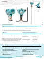
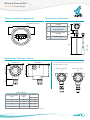
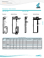
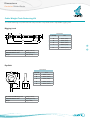
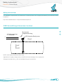
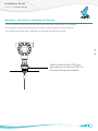
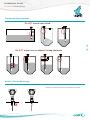
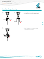
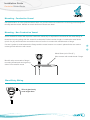
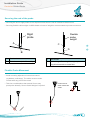
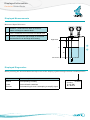
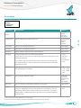
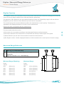
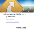
Sultan Sonar Manual Rev 1.0
A Higher Level of Performance
User Manual
Centurion
Guided Radar
CGR Series
For more information, please visit >
www.hawkmeasure.com
>
Table of Contents
Centurion Guided Radar
Contents
Overview
3
Principle of Operation
3
Function
3
19
Displayed Information
20
Features
3
Displayed Measurements
20
Primary Areas of Application
3
Displayed Diagnostics
20
Wiring & Dimensions
4
Software Parameters
21
Wiring Terminal Compartment
4
Setup Menu
21
Dimensions Housing + Gland
4
Dimensions - Reference
4
Digitize / Measured Range Reference
22
Dimensions
5
Digitize Function
22
Measured Range Reference
22
Dimensions - Probe Variants
5
Cable Weight Tank Fastening Kit
6
Software Parameters
23
Safety Instructions
7
Advanced Menu
23
CGR2 Series Wiring in Hazardous Locations
7
Setup Procedure
24
Installation Guide
8
Commissioning
24
HART
25
Mounting - Instruction for Rotating the Housing8
2
Powering The Unit For The First Time
HART Universal Command List
25
HART Common Practice List
26
10
Status / Diagnostic Flags
26
11
Software Flow Chart
27
Troubleshooting
30
Part Numbering
32
Placement Requirements
9
Nozzle / Socket Mounting
9
Stand Pipe / Flanged Mounting
Mounting - Conductive Vessel
Mounting - Non Conductive Vessel
11
Gland Entry Wiring
11
Securing the end of the probe
12
Flexible Probe Movement
12
Hardware Adjustment
13
Centurion Guided Radar System
32
Adjusting Probe Length
13
Probe Combination Table
33
Rotating Ex d Rated Enclosures (page 1 of 2)
14
Accessories
33
Flange Table
34
Specifications
35
Rotating Ex d Rated Enclosures (page 2 of 2)
15
Rotating non Ex d Rated Enclosures (page 1 of 2)
16
Rotating non Ex d Rated Enclosures (page 2 of 2)
17
Forces On The Probe
18
Ordering Instructions
38
>
<
Overview
Centurion Guided Radar
>
Principle of Operation
<
Guided-wave technology sends the radar pulse down a probe to measure either liquids or solids.
The pulse hits the surface and is reflected back up the probe to the sensor, where the transit time is
translated into a distance using time of fight and time expansion.
The amplitude of the reflection depends on the dielectric constant of the product.
Function
Primary Areas of Application
The HAWK range of Guided Radar products are ideal
• Chemicals
• Food & Beverages
for the measurement of liquids, sludge, powders
• Petrochemicals
• Oil & Gas
and granules to a range of 18.5m for level and
• Cement
• Pharmaceutical
temperature, viscosity, vacuum, foam, dust, changes
• Building Aggregates
• Pulp & Paper
in dielectric constant or coating of the probe.
• Mining / Minerals
• Wastewater
interface. This technology is not affected by pressure,
Features
• Explosion proof housing option
• Precise & continuous accuracy
• IECEx Ex d [ia] ia IIC T6 Gb Ga
• 2 wire loop
• Up to 18.5m (60ft 8in) range
• Very short minimum range (150mm, 6")
• 4-20mA, HART Universal / Common practice
commands
• Simple setup
• Protection class IP66, Nema 4x
• Auto-Calibration to any dielectric ≥ 1.5
• Measures extremely low dielectric (1.5)
• Adjustable Sensitivity
• Programmable fail safe mode
3
Wiring & Dimensions
Centurion Guided Radar
9
0
1
8
GND
Wiring
Terminal
Compartment
EMC
2
6
5
4
Dimensions - Reference
3
GND
PE (Protective Earth) screw
1
2
+
-
3
Housing
Gland / Gland + High
Threaded Connection
/ Flange
109mm (4.3”)
110mm (4.33”)
109mm (4.3”)
Approval
Option*
GL
mmin
1
XX
502.0
1
1D
572.2
2
XX
1365.3
2
1D
973.5
*Consult Part Numbering / Specifications for technical information
4
GL
GL
Gland Length (GL)
Option*
(4)
16
Housing with Process Temperature option ‘2’.
Visual reference only.
Approval Option
1D
GL
109mm (4.3”)
87mm (3.4”)
160mm (6.3”)
Process Temperature
(3)
Probe Length
Probe Entry
Material
110mm (4.33”)
(2)
110mm (4.33”)
4
Dimensions Housing + Gland
(1)
Temp. Extension
87mm (3.4”)
7
87mm (3.4”)
+
Approval Option
XX
>
<
Dimensions
Centurion Guided Radar
Dimensions - Probe Variants
B04 / B06 / B08
A04 / A06 / A08
Welded Flange
H
G
G
G
E
A
A
A
Probe Length
Probe Length
Probe Length
Probe Length
Probe Length
Probe Length
Probe Length
Probe Length
>
A
A
Probe Length
Probe Length
Probe Length
Probe Length
Probe Length
A
A
J
C
C
C
C
C
C
C
J
B
D
D
D
D
B
B
B
D
B
B
D
B
Probe / Cable Dimensions
Probe
Type
A04, B04
THD
BSP or NPT
in.
mmin.
mmin.
mmin.
mmin.
mmin.
D
Internal Threads
(A04, A06, A08 only)
3/4
40.16
220.9
1204.7
451.8
401.6
M10x1.25, 24mm deep
A
B
C
E
F
J
(Tightening Torque = 20Nm)
Set Screw
3x M8x1.25x12
Hex Key Size
4mm
A06, B06
1
60.24
281.1
1505.9
451.8
401.6
M10x1.25, 24mm deep
3x M8x1.25x12
4mm
A08, B08
1-1/2
80.31
361.4
2007.8
722.8
642.5
M10x1.25, 24mm deep
3x M10x1.5x18
5mm
Welded
Flange
G
H
mmin.
mmin.
A04, B04
451.8
421.6
A08, B08
722.8
702.7
5
<
Probe Length
A
Probe Length
A
A
J
C
D
B
H
G
E
E
A
A
J
H
H
H
F
G
THD
E
E
H
G
THD
A
A
A
F
F
E
F
Welded Flange
G
H
F
THD F
THD
G
F
F
Threaded
E
Threaded
Dimensions
Centurion Guided Radar
Cable Weight Tank Fastening Kit
The tank fastening kit (CGR-A0X-WL-SS) includes 2 eye bolts and 1 adjustable rigging lock.
Rigging Lock
H
T
Dimensions
L1
A
D
L
A
Recommended Working Load
983kg (1.05 ton)
Total Deformation Load
3750kg (4.13 ton)
Weight
H
T
H
C
L1
Eye Bolt
A
D
L
D
T
Dimensions
A
T (thread)
M10
A
40mm (1.57")
B
25mm (0.98")
B
H
C
D
T
6
Recommended Working Load
675kg (0.74 ton)
Total Deformation Load
2600kg (2.87 ton)
Weight
60g (0.13lb)
M12
A
14mm (0.55")
D
12mm (0.47")
H
25mm (0.98")
L
252mm (9.9")
L1
150mm (5.9")
>
<
576g (1.27lb)
B
T (thread)
C
21mm (0.82")
D
20mm (0.79")
H
63mm (2.48")
Safety Instructions
Centurion Guided Radar
Safety Instructions
For installation requirements for Hazardous Locations please refer to appropriate Safety Instruction document
located at:
http://www.hawkmeasure.com/productdetail.asp?id=57
CGR2 Series Wiring in Hazardous Locations
See terminal
compartment wiring
4-20mA current loop
U = 14-28VDC
+
-
+
-
PE (Protective Earth) screw
Zone 1
Zone 1
or
Zone 0
NOTE: (Ref Safety Instructions Sect 10a)
Application of supply voltages above 28VDC will cause damage to the equipment.
Voltages less than the Um will not invalidate the type of protection.
7
>
<
Installation Guide
Centurion Guided Radar
Mounting - Instruction for Rotating the Housing
There are specific rotation points which should be used while mounting the unit into place.
The Housing Compartment should never be used to rotate the device during mounting.
For rotating the housing after installation see 'Rotating the Enclosure' section.
>
<
When Installing the CGR unit,
use spanner or wrench ONLY at
Process Fitting as indicated.
8
Installation Guide
Centurion Guided Radar
Placement Requirements
Do NOT mount near infeed
>
<
Do NOT mount over or adjacent to any obstacles
Nozzle / Socket Mounting
Nozzle / Socket should not protrude into vessel
X
9
H
X
Installation Guide
Centurion Guided Radar
H
X
D
Stand Pipe / Flanged Mounting
1
1. Stand pipe should not protrude into vessel.
2
2. Do not mount in long narrow stand pipe.
H
X
H
T
D
X
D
D
X
>
<
3
3. Roof Thickness (T) should not exceed
Diameter (D) of cut away.
T
T
D
10
XX
D
X
Installation Guide
Centurion Guided Radar
24VDC +-
CGR unit
with HART
250ohm
Mounting - Conductive Vessel
A
Unit performance is most optimized when there is a ground reference between the mounting (metal flange or
thread) and the vessel. Metallic or metal reinforced vessels are ideal.
ProComSol HART modem or
Sense USB HART modem
HART
modem
Mounting - Non Conductive Vessel
PC with GoshawkII in
HART comms mode
B
GoshawkII
A non conductive vessel will require a conductive metal strip or equivalent connected to the metal flange or
thread and running along side the vessel for at least the Probe insertion length. A conductive metal sheet
(min 0.5m (8") should also be mounted on the roof and be in contact with metal thread or flange.
If a seal / gasket is used between the flange and the vessel ensure non coated / painted bolts are used to
create ground reference with vessel.
>
<
Metal Sheet (min 0.5m (8")
Must contact with metal thread / flange
Metallic strip connected to flange /
mounting thread and running along
side of non-metallic vessel
Gland Entry Wiring
24VDC
With suitable +esistor
11
Wire at gland entry
must angle down
CGR unit
with HART
Do NOT mount adjacent to infeed
Installation Guide
Centurion Guided Radar
Securing the end of the probe
• Securing the end of rigid probes is not required unless there is risk of excessive lateral forces.
• Securing flexible cable weight via M10 thread on base of weight is recommended to prevent movement.
xible
be
ght
Rigid
probe
Flexible
probe
weight
A
C
D
B
A
Metal socket
B
Floor clearance (min 50mm, 2")
>
C
M10 thread
MetalDflange
Cable Weight Fastening Kit or appropriate O
Nozzle
ring & link secured to vessel floor.
Probe must not
make contact with
Flexible Probe Movement
vessel
• Avoid mounting adjacent to
internal structures
Min 100mm
(eg ladders, walkways). The cable must not make contact with any part of the vessel
• Take into consideration that material forces may
push probe laterally. Secure Cable Weight if required.
to infeed
Metal flange
12
Flexible
probe
Probe must not
make contact with
vessel
A
<
Hardware Adjustment
Centurion Guided Radar
Adjusting Probe Length
Rigid Probes
Cut rigid probes to appropriate length. After adjustment, you must change the 'ProbeLength' Parameter in
'Advanced' menu to represent the new length (password 222).
Flexible Probes
(a) Mark the point at which the flexible cable enters the cable weight.
(b) Release the cable weight grub screws with hex key.
(c) Measure and note the length of cable concealed within cable weight.
(d) Cut cable noting the length of cable must include the concealed length above.
(e) Re-insert the cable into the weight and tighten grub screws to tightening Torque of 20Nm.
Use loctite 243 or equivalent on grub screws to secure once completed.
(f) Adjust ProbeCalibr Parameter in 'Advanced' menu to represent new length (password 222).
13
>
<
Hardware Adjustment
Centurion Guided Radar
Rotating Ex d Rated Enclosures (page 1 of 2)
The Ex d gland which couples the sensing probe to the flameproof enclosure provides a critical sealing
function for the enclosure. Internal wires are passed through this gland and the high integrity seal. This
gland incorporates a Union Joint which is designed to rotate.
However this rotation is limited to one-time adjustment of Display orientation after installation on site, as
shown below:
ONLY one 36mm spanner applied to the Hex of Union Joint to rotate enclosure to desired orientation as
allowed. DO NOT hold the enclosure during this procedure.
>
<
As Installed, but LCD display
not visible.
Rotation at Union Joint
Desired Orientation.
Max 180° allowable one-time
rotation in either direction.
Rotation beyond these strict limits can damage the internal cables
Ensure Enclosure follows the spanner rotation and assembly integrity is not compromised
14
Hardware Adjustment
Centurion Guided Radar
Rotating Ex d Rated Enclosures (page 2 of 2)
36mm
36mm
This is a Sealed
Threaded Joint.
Plane of Rotation
It must NOT
be loosened or
broken.
<
When Installing the CGR
unit, use spanner or
wrench ONLY at Process
Fitting as indicated.
15
>
Hardware Adjustment
Centurion Guided Radar
Rotating non Ex d Rated Enclosures (page 1 of 2)
The gland which couples the sensing probe to the enclosure provides a critical sealing function for
the enclosure. Internal wires are passed through this gland and the high integrity seal. This gland
incorporates a Union Joint which is designed to rotate.
However, this rotation is limited to one-time adjustment of Display orientation after installation on site,
as shown below:
ONLY one 36mm spanner applied to the Hex of Union Joint to rotate enclosure to desired orientation as
allowed. DO NOT hold the enclosure during this procedure.
>
<
As Installed, but LCD display
not visible.
Rotation at Union Joint
Desired Orientation.
Max 180° allowable one-time
rotation in either direction.
Rotation beyond these strict limits can damage the internal cables
Ensure Enclosure follows the spanner rotation and assembly integrity is not compromised
16
Hardware Adjustment
Centurion Guided Radar
Rotating non Ex d Rated Enclosures (page 2 of 2)
36mm
This is a Sealed
Threaded Joint.
It must NOT
be loosened or
broken.
Plane of Rotation
<
When Installing the CGR
unit, use spanner or
wrench ONLY at Process
Fitting as indicated.
17
>
Forces On The Probe
Centurion Guided Radar
Forces on the probe
Tensile forces are heavily dependent on the viscosity and abrasive characteristics of the product in the vessel.
Ensure tensile loading is appropriate for the selected cable as well as the silo cover and mounting structure.
In critical cases it is better to select the larger flexible cable (8mm).
Probe Type
Tensile Load
A04 (4mm flexible cable @ 20ºC, 68ºF)
0.5 Ton
A06 (6mm flexible cable @ 20ºC, 68ºF)
1.0 Ton
A08 (8mm flexible cable @ 20ºC, 68ºF)
4.0 Ton
>
Lateral forces can exist due to movement and gradual flow of the product in the vessel, particularly with
powder and granular materials.
These forces can cause stress and strain on the probe, as well as the process fitting and mounting hardware.
Ensure that lateral forces are minimized by following the installation guidelines and Placement Requirements.
Probe Type
Lateral Load
B04 (4mm rigid probe @ 20ºC)
1 Nm
B06 (6mm rigid probe @ 20ºC)
3 Nm
B08 (8mm rigid probe @ 20ºC)
8 Nm
18
<
Powering The Unit For The First Time
Centurion Guided Radar
Installation should only be performed by suitably qualified personnel.
A. Confirm mounting is within recommended specifications.
B. Check the selected unit matches the required application specifications.
For Hazardous Locations see appropriate safety instructions available at http://www.hawkmeasure.com
C. Check the wiring is correct and all connections are secure.
D. Apply power to the unit.
When power is applied the unit will start its normal load sequence.
The following messages will cycle on the display.
>
Hawk
CGR Series
Serial Number
Software Revision
<
Menu Navigation
1
Navigate up, increase value
2
1 value
Navigate down, decrease
1
3
Proceed, select, save
4
Go back, return unit to operational mode
1
1
2
2
2
2
3
3
3
3
EN URION
EN URION
EN URION
EN URION
4
4
4
4
1
2
EN URION
4
3
High Level
Level
High
High Level
High Level
A
A
A
A
A
A
A
A
B
B
B
B
C
C
C
C
19
B High Level
B
B
B
A
A
Displayed Information
Centurion Guided Radar
1
EN URION
3
Displayed Measurements
Measured Span Reference
A
Distance - measured from base of thread or
bottom of flange to material level
B
Level - measured from Low level to material level
C
% Level - proportional percentage of measured
level based on Low and High level setting
A
High Level
A
>
B
C
<
B
Low Level
C
Displayed Diagnostics
Software Flow Chart
TDR Revision
While pressing the arrow buttons the top corner of the display
cycles2through various unit diagnostics
mA
Current output in mA
Normal
Unit operating normally
Standard Operating Mode
LEVEL (m)
Press
Failed
Unit in failsafe conditions
Recover
Unit searching for level / attempting to amplify signal
2.525
Standard Operating Mode
20.0mA
Level(m)
2.525
mA diagnostic
Echo d7.5
Press & hold CAL for 3
seconds & release button
to access AutoSet
LEVEL (m)
2.525
Echo distance & size
Echo s1.5
LEVEL (m)
2.525
Sensitivity value
20
D
Software Parameters
Centurion Guided Radar
Echo s1.5
Device ID (For HART, FF, PA)
LEVEL (m)
2.525
Sensitivity value
Tag xxxxxxx
LEVEL (m)
2.525
Instrument Tag ID
Setup Menu
Main Menu
Main Menu
Setup
Advanced
Autoset
Setup
Display Mode
Display Unit
Hi Level
Low Level
Damping
Parameter
Main
Menu Description Fail Mode
Display
Select default Display mode
Main Menu
Mode
Setup
Advanced
Autoset
Display Unit
AutoSet
Adjust displayed measurement unit
Advanced
Comms
Tracking
Sensitivity
Digitize
Cal Mount
Echo Size
Analogue
Factry Reset
Device Info
Lock Code
Language
Options
Volume(2)
Level
%Level
Distance
Centimeters
Metres
Feet
Inches
Low
Level
Low
Level
Set Low Level (4mA) distance
Adjustable
HiDigitize
Level
Set High Level (20mA) distance
Adjustable
Hi Level
AutoSet - link to standard Low Level, High Level & Digitise
Damping
Adjust output response time & smoothness
Adjustable
Tracking
Program application Fill and Empty speeds.
• Fast
• Medium
• Slow
• InstaTrack
• Test
InstaTrack is a special mode which we respond immediately to any
detected reflection.
'Test' Mode adjusts unit function to be suitable for bench testing
and demonstration. The unit will track nearest detected reflection
regardless of size.
Dielectric
Applies a pre-set value to Sensitivity based on selected Dielectric
Constant range of material.
• <2 • <5
• <10 • <20
• <40 • <80
• >80
Fail Mode
Set Analogue failsafe output
3.50mA
20.20mA
LastKnown
4mA
20.00mA
Fail Time
Set time delay for FailSafe condition (in seconds)
Adjustable
Digitize
Perform auto-Digitization routine to set Sensitivity and digital false
reflection mapping based on the application conditions. The unit
will display either the measured level or end of probe. The value
is adjustable. If adjusting ensure the value is not greater than the
material level.
• Yes
• No
(1) See 'Measured Range Reference' on next page
(2) Volume activation requires Goshawk. See dedicated CGR Goshawk manual.
21
>
<
(1)
Digitize / Measured Range Reference
Centurion Guided Radar
Digitize Function
The 'Digitize' function is an automatic setup routine used to eliminate false reflections and apply the Sensitivity
value for the unit (which is based on the selected Dielectric parameter).
The selection of the 'Dielectric' pre-set creates a base line for the unit's Sensitivity range it will use after the
Digitization process. Select a lower Dielectric pre-set if there is any doubt.
The unit will prompt the measured distance (either the material level or end of probe). The distance is
adjustable if the displayed distance is not the correct material level.
Ensure the value is not greater than the material level.
For best results follow this routine:
1) Ensure the unit is mounted according to mounting specifications and requirements.
>
2) Ensure the material to be measured is in contact with the actively measured part of the probe.
<
3) Select Dielectric pre-set value of most similar to material to be measured.
4) Run Digitize routine. Confirm displayed distance is either material level or end of probe if vessel is empty.
Measured Range Reference
CGR unit
A
Blanking (non-measurable zone)
B
with HART
Measurable Span (blanking to top of cable weight
or end of
24VDC +rigid probe).
250ohm
High level must be = to or > than Blanking
ProComSol HART modem or
Sense USB HART modem
Minimum Range (Blanking)
Probe
Variant
PC with GoshawkII in
HART comms mode
A
HART
modem
Maximum Range
Probe
B
GoshawkII
Variant
A04
150mm (6")
A04
18.5m (60ft 8in)
A06
150mm (6")
A06
18.5m (60ft 8in)
A08 150mm (6")
A08
18.5m (60ft 8in)
B04
150mm (6")
B04
4m (13ft 1in)
B06 150mm (6")
B06
4m (13ft 1in)
B08
150mm (6")
B08
4m (13ft 1in)
22
A
B
Instrument Tag ID
Software Parameters
Centurion Guided Radar
Main Menu
Main Menu
Setup
Advanced
Autoset
Advanced Menu
Main Menu
Setup
Display Mode
Display Unit
Hi Level
Low Level
Damping
Fail Mode
Main Menu
Setup
Advanced
Autoset
Advanced
Comms
Tracking
Sensitivity
Digitize
Cal Mount
Echo Size
Analogue
Factry Reset
Device Info
Lock Code
Language
Parameter
Description
Options
Comms
AutoSet
Adjust communication protocol settings. The default ID is 0, and the
• Device ID
• Baud Rate
Sensitivity
Digitize
Manual adjustment of Sensitivity. Digitize automatically sets this value
based on application conditions. Sensitivity is the primary adjustment
for the unit's ability to detect media
• 0-100
Blanking is a non-measurable zone. This can be increased to ‘Blank’
out high level false echoes caused by mounting
• Adjustable
Adjust Analog output. Switch from 4-20mA to 20-4mA
• 4-20
• 20-4
• 4mA tuning
• 20mA tuning
• Park 4mA
• Park 8mA
• Park 12mA
Low Level
Hi Level
Blanking
Analog
default baud
rate -islink
1200.
AutoSet
to standard Low Level, High Level & Digitise
Fine tune both 4mA current and 20mA current reading
Park (Lock) Current to 4, 8 or 12mA.
>
<150mm (3") is not
recommended
Factry Reset
Restore all parameters to factory default.
Device Info
Display device information
Lock Code
Enable / Disable lock code. If enabled, select lock code number.
• Enable / Disable
ProbeCalibr
If physical length of probe is adjusted you must run this routine for the
system to re-detect the probe end. Nothing should be touching the
probe when commencing this function.
• Adjustable
Do not adjust the probe length of hazardous location rated units
Dist Calibr
Calibrate distance correction factor. Some applications or
environments can affect time of flight signal travel affecting the
measured distance reading . This function allows the detected distance
to be adjusted to suit the application.
23
• Yes
• No
• Password
protected (222)
• Adjustable
<
Setup Procedure
Centurion Guided Radar
Commissioning
For commissioning via PC and Goshawk see dedicated CGR Goshawk Manual.
Parameter
Instruction
1. Set High and Low level
High and Low level distances can be programmed manually or you can run
Autoset. Autoset can be used to program the High or Low level based on the
material level which is touching the probe when the function is run.
2. Set Tracking Speeds
Tracking speeds can be set to Fast, Medium, Slow and Custom (measured in
Displayed Units per hour)
3. Select application Dielectric
Choose closest Dielectric range from the pre-set list. Select lower value if unsure.
3. Run Digitize
Run the CGR Digitize routine to automatically set the reflection mapping and
Sensitivity range for the installation. This function can be performed in both empty
vessel or with material contacting the probe.
You will be prompted to enter a distance value (measured from base of probe
down). This will either be the material level or the end of probe.
If material level is not displayed, choose a lower Dielectric
4. Add Damping
Increasing Damping value if a smoother response trend is required. This value is
automatically set by the Tracking speed.
5. Run unit
Press RUN several times to commence unit operation
24
>
<
HART
Centurion Guided Radar
HART Universal Command List
Revision 5
Universal Commands
Command No.
Function
0
Read unique identifier
1
Read Primary Variable
2
Read current and percent of range
3
Read current and four predefined dynamic variables.
6
Write polling addr
7
Read loop configuration
8
Read Dynamic Variable Classifications
11
Read unique ident. Associated with tag
12
Read message
13
Read Tag, Description, Date
14
Read PV sensor information
15
Read output information
16
Read final assembly number
17
Write message
18
Write Tag, Description, Date
19
Write final assembly number
20
Read Long Tag
25
>
<
HART
Centurion Guided Radar
HART Common Practice List
Revision 5
Common Practice Commands
Command No.
Function
34
Write Primary Variable Damping Value
35
Write Primary Variable Range Value
36
Set Primary Variable Upper Range Value
37
Set Primary Variable Lower Range Value
38
Reset Configuration Changed Flag
40
Enter/Exit Fixed Primary Variable Current Mode
44
Write Primary Variable Units
45
Trim Primary Variable Current Dac Zero
46
Trim Primary Variable Current Dac Gain
57
Read Unit Tag, Descriptor, Date
58
Write Unit Tag, Descriptor, Date
59
Write Number Of Response Preambles
109
Burst Mode Control
110
Read All Dynamic Variables
Status / Diagnostic Flags
Status / Diagnostic Flags
Device Malfunction (Fails safe status)
Configuration Changed
Cold Start
Output Current Fixed
Primary Variable Out of limits
26
>
<
Software Flow Chart
Centurion Guided Radar
Diagnostics
Autoset
__mA
Normal
Set Lo Level
or
Recover
or
CAL
Failed
No
Yes
Set Hi Level
CAL
No
Yes
Volume
Setup
Display Mode
CAL
Level
%Level
Distance
CenMeter
Display Unit
CAL
Metres
Feet
Inches
High Level
Low Level
27
Tracking
CAL
Slow
>
<
Software Flow Chart
Centurion Guided Radar
< 80
> 80
Digitize
CAL
No
Yes
CAL
DigitizeDist
CAL
Confirm?
Yes / No
Damping
3.80mA
20.20mA
>
<
Last Known
4mA
FailSafe
CAL
20mA
CAL
DeviceID
FailTime
Advanced
Comms(HART)
Baud Rate
Blanking
Sensitivity
Offset Dist
28
Dist Calibrt
CAL
No
Blanking
Software
Flow Chart
Centurion Guided Radar
Yes
CAL
Calibrt Dist
CAL
Probe Length
ProbeLength
CAL
EntrPassword
Analog
CAL
4mA-20mA
Sensitivity
Offset Dist
Dist Calibrt
20mA-4mA
CAL
4mA Tuning
No
20mA Tuning
Yes
CAL
Calibrt Dist
CAL
Probe Length
ProbeLength
CAL
EntrPassword
Analog
CAL
4mA-20mA
Park 4mA
Park 12mA
Factry Reset
CAL
20mA-4mA
Language
A
CAL
English
CAL
Disable
Lock Code
Park 4mA
Enable
Park 8mA
Park 12mA
No
Yes
Language
CAL
English
CAL
Disable
A Info
Device
29
Lock Code
CAL
Confirm Sel?
Yes / No
CAL
Unlock Code
Device Info
20mA Tuning
CAL
>
No
Yes
4mA Tuning
Factry Reset
Park 8mA
CAL
Confirm Sel?
Yes / No
<
Troubleshooting
Centurion Guided Radar
Troubleshooting
Problem
Display is blank
Unit continually re-starts
Check
Check incoming power on loop is to specification.
Check incoming power on loop is continuous.
Bench test with new 24V supply.
Run Digitize routine. If routine has already been run, Lower Dielectric selection or
increase Sensitivity parameter.
Measurement is nonresponsive (material
touching probe)
Check unit status for 'Failsafe'. The unit will go to Failsafe if it cannot detect any
reflections. Check the probe element for damage or excessive build up.
Ensure mounting is correct to specification with good ground reference. Ensure probe
is not touching the vessel.
>
Place current meter in line with loop. Ensure the 4-20mA is proportional to level reading
based on High and Low level.
<
A) If the unit is indicating full / high
Ensure no structure is making contact with the probe. Check for build up bridging
between the probe and vessel / nozzle
Run Digitize routine while no material is contacting the probe.
Set Display Mode to Distance, note the measurement. If distance is near high level use
Blanking to eliminate reflection interference. Adjust High level to ensure it is not within
the Blanking range.
Unit is indicating a
material level while no
material is present
B) If the unit is indicating other level
The unit should measure the end of probe while nothing is touching the probe.
Run Digitize routine while no material is contacting the probe.
Confirm 'Low Level' is set correctly.
Ensure no structure is making contact with the probe. Check for excessive build up and
clean the probe.
Ensure mounting is correct to specification with good ground reference.
Place current meter in line with loop. Ensure the 4-20mA is proportional to level reading
based on High and Low level. Use 4mA and 20mA tuning to force the output reading to
each value to ensure the current control is operating correctly.
PLC reading does
not match reading on
display
30
Connect a Multimeter in series with the powered loop. Compare the 'mA' diagnostic on
the display with the mA reading on the loop. If these values do not match, disconnect
the loop wires and measure the resistance across the loop. This should not exceed
specification.
Confirm High Level and Low Level are set to the same values in CGR and control
system.
Troubleshooting
Centurion Guided Radar
Troubleshooting (con't)
The material touching the probe may not be generating a large enough reflection in the
application conditions.
Unit measurement is
locked at or near end of
probe
Ensure unit is mounted as per specifications. Take note of the ground reference
requirement. Ensure the probe is not making contact with the vessel.
Use a minimum 2" / 50mm flange to improve signal transmission.
Change unit Tracking to 'Demo' mode to measure closest echo instead of largest.
Increase Sensitivity.
The probe is too long
Non-hazardous rated units can have the probe length cut to requirement.
For flexible probes release the cable weight by undoing grub screws.
>
After adjusting the probe ensure the new probe length is recorded on site.
Update ProbeCalibrt parameter to new length.
<
Do not adjust the probe of hazardous location rated units.
Adjusting /
commissioning the unit
without removing the lid
You will require a HART to PC connector and HAWK GoshawkII software.
See 'CGR Goshawk user manual' for further information.
The digitization process will fail if the unit cannot detect a measurable difference
between the largest false reflection and the reflection generated by either the end of
probe or the material touching the probe.
Choose a lower Dielectric pre-set and re-run Digitize.
Digitize Fails
Increase Sensitivity value and re-run Digitize.
Ensure the Digitize distance is not greater than the material level.
Ensure no structure is making contact with the probe. Check for excessive build up and
clean the probe.
Ensure mounting is correct to specification with good ground reference.
If Digitize displays a closer distance than the material level / end of probe enter the
distance to the correct material level. The unit will automatically eliminate the detected
echo and find the correct level.
Digitize displays
incorrect distance
If Digitize displays a longer distance than the material level the measured material may
not be returning a large enough signal. Increase Sensitivity and change Tracking to
'Test' mode. Ensure unit has conforming ground reference.
If Digitize displays a longer distance than the end of the probe length adjust see
'Measurement Accuracy' below or the 'ProbeLength' parameter in 'Advanced' menu if
the Probe length has been modified.
Measurement Accuracy
31
Material / Dielectric or environment can create small measurement inaccuracy.
Run Dist Calibrt parameter in software to manually adjust measured distance to
new value.
Part Numbering
Centurion Guided Radar
Centurion Guided Radar System
Model
CGR2 2 wire Centurion Guided Radar
Communication
H 4-20mA with HART
Housing
1 Aluminum, Epoxy Painted
2 316L Stainless Steel
Gland Entry
1 1/2” NPT Cable gland entry 2 3/4” NPT Cable gland entry 3 M20 x 1.5 Cable gland entry 4 M25 x 1.5 Cable gland entry Probe Type3
A04 4mm flexible cable
A06
6mm flexible cable
A08
8mm flexible cable
B04 4mm rigid probe
B06 6mm rigid probe
B08 8mm rigid probe
>
<
3
Probe variant / materials
S316L
Mounting 3
TN07
3/4” NPT Thread (316L) or threaded flange mount 2
TB07
3/4” BSP Thread (316L)
TN10
1” NPT Thread (316L)
TB10
1” BSP Thread (316L)
TN15
1.5” NPT Thread (316L) or threaded flange mount 2
TB15
1.5” BSP Thread (316L)
1
FXXX Pre-Welded Flange (replace XXX with 3 character Welded Flange Code)
Process O-ring seal
V
FKM (Viton) (-20°C to +204°C)
B
NBR (-35°C to +110°C)
S
Silicone (-60°C to +230°C)
Process Temperature
1
-40ºC to +80ºC (-40 to +176ºF)
2
-40ºC to +150ºC (-40 to +302ºF)
Process Pressure
1
5 bar
3
20 bar
4
40 bar
Approval Standard
XXNot Required
1D
IECEx Ex d [ia] ia IIC T6 Gb Ga
A2
ATEX Grp II Cat 3 GD IP66 Tamb -40°C to 60°C
Probe Length3
Specify in cm to the nearest 10cm
CGR2 H13B04STN15 B111D 200
1
See Weld Code selection in Flange Table.
Order flange as separate line item. See Probe / Mounting combination table matching size and variants options.
See Flange Table Accessory Code for ordering.
2
3
See Probe Table for valid Probe, Variant / Materials, Mounting and Length combinations prior to selection
32
Part Numbering
Centurion Guided Radar
Probe Combination Table
Probe / Mounting Combination Table
Each line represents valid part combinations
Flange Sizes
Min. Size
Max size
Max. Length
Probe Code
Variant / Materials
Mounting
A04
S
TN07, TB07, FXXX
1”, DN25, 25mm
1-1/2”, DN40, 40mm
1850cm
A06
S
TN10, TB10
N/A
N/A
1850cm
A08
S
TN15, TB15, FXXX
2”, DN50, 50mm
4”, DN100, 100mm
1850cm
B04
S
TN07, TB07, FXXX
1”, DN25, 25mm
1-1/2”, DN40, 40mm
400cm
B06
S
TN10, TB10
N/A
N/A
400cm
B08
S
TN15, TB15, FXXX
2”, DN50, 50mm
4”, DN100, 100mm
400cm
>
<
Accessories
Tank Fastening Kit
CGR-A0X-WL-SS
Kit includes:
Qty1 RIGGING-SCR-JAW-JAW-SS-M12
Qty2 EYEBOLT-SS-M10
33
Flange Table
Centurion Guided Radar
Flange Table
Accessory Code
Welded
Type (all options Blind Flanges)
Material
Code
Bore Hole
Matching Mounting Thread
(threaded type only)
(threaded type only)
FLA-1A1-SS-TN07
F1A1
1” ANSI B16.5 150LB
316L
3/4” NPT
TN07
FLA-1A3-SS-TN07
F1A3
1” ANSI B16.5 300LB
316L
3/4” NPT
TN07
FLA-1A6-SS-TN07
F1A6
1” ANSI B16.5 600LB
316L
3/4” NPT
TN07
FLA-1A9-SS-TN07
F1A9
1” ANSI B16.5 900LB
316L
3/4” NPT
TN07
FLA-1AA-SS-TN07
F1AA
1” ANSI B16.5 1200LB
316L
3/4” NPT
TN07
FLA-1AB-SS-TN07
F1AB
1” ANSI B16.5 2500LB
316L
3/4” NPT
TN07
FLA-HA1-SS-TN07
FHA1
1-1/2” ANSI B16.5 300LB
316L
3/4” NPT
TN07
FLA-HA3-SS-TN07
FHA3
1-1/2” ANSI B16.5 600LB
316L
3/4” NPT
TN07
FLA-HA6-SS-TN07
FHA6
1-1/2” ANSI B16.5 900LB
316L
3/4” NPT
TN07
FLA-HA9-SS-TN07
FHA9
1-1/2” ANSI B16.5 900LB
316L
3/4” NPT
TN07
FLA-HAA-SS-TN07
FHAA
1-1/2” ANSI B16.5 1200LB
316L
3/4” NPT
TN07
FLA-HAB-SS-TN07
FHAB
1-1/2” ANSI B16.5 2500LB
316L
3/4” NPT
TN07
FLA-2A1-SS-TN15
F2A1
2” ANSI B16.5 150LB
316L
1.5” NPT
TN15
FLA-2A3-SS-TN15
F2A3
2” ANSI B16.5 300LB
316L
1.5” NPT
TN15
FLA-2A6-SS-TN15
F2A6
2” ANSI B16.5 600LB
316L
1.5” NPT
TN15
FLA-2A9-SS-TN15
F2A9
2” ANSI B16.5 900LB
316L
1.5” NPT
TN15
FLA-2AA-SS-TN15
F2AA
2” ANSI B16.5 1200LB
316L
1.5” NPT
TN15
FLA-2AB-SS-TN15
F2AB
2” ANSI B16.5 2500LB
316L
1.5” NPT
TN15
FLA-3A1-SS-TN15
F3A1
3” ANSI B16.5 150LB
316L
1.5” NPT
TN15
FLA-3A3-SS-TN15
F3A3
3” ANSI B16.5 300LB
316L
1.5” NPT
TN15
FLA-3A6-SS-TN15
F3A6
3” ANSI B16.5 600LB
316L
1.5” NPT
TN15
FLA-3A9-SS-TN15
F3A9
3” ANSI B16.5 900LB
316L
1.5” NPT
TN15
FLA-3AA-SS-TN15
F3AA
3” ANSI B16.5 1200LB
316L
1.5” NPT
TN15
FLA-3AB-SS-TN15
F3AB
3” ANSI B16.5 2500LB
316L
1.5” NPT
TN15
FLA-4A1-SS-TN15
F4A1
4” ANSI B16.5 150LB
316L
1.5” NPT
TN15
FLA-4A3-SS-TN15
F4A3
4” ANSI B16.5 300LB
316L
1.5” NPT
TN15
FLA-4A6-SS-TN15
F4A6
4” ANSI B16.5 600LB
316L
1.5” NPT
TN15
FLA-4A9-SS-TN15
F4A9
4” ANSI B16.5 900LB
316L
1.5” NPT
TN15
FLA-4AA-SS-TN15
F4AA
4” ANSI B16.5 1200LB
316L
1.5” NPT
TN15
FLA-4AB-SS-TN15
F4AB
4” ANSI B16.5 2500LB
316L
1.5” NPT
TN15
FLA-1D1-SS-TN07
F1D1
DN25 DIN2527 PN16
316L
3/4” NPT
TN07
FLA-1D4-SS-TN07
F1D4
DN25 DIN2527 PN40
316L
3/4” NPT
TN07
FLA-HD1-SS-TN07
FHA1
DN40 DIN2527 PN16
316L
3/4” NPT
TN07
FLA-HD4-SS-TN07
FHD4
DN40 DIN2527 PN40
316L
3/4” NPT
TN07
FLA-2D1-SS-TN15
F2D1
DN50 PN16
316L
1.5” NPT
TN15
FLA-2D4-SS-TN15
F2D4
DN50 PN40
316L
1.5” NPT
TN15
FLA-3D1-SS-TN15
F3A1
DN80 PN16
316L
1.5” NPT
TN15
FLA-3D4-SS-TN15
F3D4
DN80 PN40
316L
1.5” NPT
TN15
FLA-4D1-SS-TN15
F4A1
DN100 PN16
316L
1.5” NPT
TN15
FLA-4D4-SS-TN15
F4D4
DN100 PN40
316L
1.5” NPT
TN15
FLA-1J1-SS-TN07
F1J1
JIS 25mm 16k
316L
3/4” NPT
TN07
FLA-1J4-SS-TN07
F1J4
JIS 25mm 40k
316L
3/4” NPT
TN07
FLA-HJ1-SS-TN07
FHJ1
JIS 40mm 16k
316L
3/4” NPT
TN07
FLA-HJ4-SS-TN07
FHJ4
JIS 40mm 40k
316L
3/4” NPT
TN07
FLA-2J1-SS-TN15
F2J1
JIS 50mm 16k
316L
1.5” NPT
TN15
FLA-2J4-SS-TN15
F2J4
JIS 50mm 40k
316L
1.5” NPT
TN15
FLA-3J1-SS-TN15
F3J1
JIS 80mm 16k
316L
1.5” NPT
TN15
FLA-3J4-SS-TN15
F3J4
JIS 80mm 40k
316L
1.5” NPT
TN15
FLA-4J1-SS-TN15
F4J1
JIS 100mm 16k
316L
1.5” NPT
TN15
FLA-4J4-SS-TN15
F4J4
JIS 100mm 40k
316L
1.5” NPT
TN15
34
>
<
Specifications
Centurion Guided Radar
Electronics
Power
Memory
• 2 wire loop powered
• 24VDC (14 to 28VDC)
• Non-Volatile (No backup battery required)
>10 years data retention
Power Consumption
Operating Temperature (Electronics)
• <500mW @ 24VDC
• -40ºC to +80ºC (-40 to +176ºF)
Analog Output
Display
• 14V @ 0 Ohm
• 4 line graphic display (128 x 64 pixels)
• 19V @ 250 Ohms
Language
• 24V @ 500 Ohms
• English
• Current park at 4mA, 8mA, 12mA
Communications*
• HART (Revision 5, Universal & Common Practice commands).
• GoshawkII via HART. Full parameter list
Maximum Range
• Flexible cable probe:18.5m (60ft 8in)
• Rigid probe: 4m (13ft 1in)
Minimum Range (Blanking)
• 150mm (6")
Dielectric Range
• ≥ 1.5
Frequency
• 2.2 GHz
Resolution
• Analog: 1uA
• Display: 1.0mm
Configuration
• 4 button (Up, Down, Cal, Run), GoshawkII via HART
Approvals*
• IECEx Zone 0/1, Zone 1
IECEx TSA 14.0037X
Ex d [ia] ia IIC T6 Gb Ga
Tamb = -40ºC to +60ºC (-40 to +140ºF)
IP 66, NEMA 4X
(T6 … T1)
• ATEX Grp II Cat 3 GD IP66 Tamb -40°C to 60°C
Cable Entries
• 1/2” NPT
• 3/4” NPT
• M20 x 1.5
• M25 x 1.5
Enclosure
Type
• Dual Compartment with Glass window
Accuracy 1
Material
• +/- 3mm
• Die-cast Copper-Free Aluminum, Epoxy Painted
Measurements per second
• 316L Stainless
•3
Cable Entries
Response Time
• 1/2” NPT
• <1 second (based on application selection)
• M20 x 1.5
• 3/4” NPT
Sum of non linearity, non repeatability, hysteresis
• M25 x 1.5
• Analog +/- 0.02%
IP Rating
Repeatability
• NEMA 4X
• +/- 3mm
• IP66
*Specifications model dependent. Consult part number listing.
1
35
Accuracy dielectric & material dependent
>
<
Specifications
Centurion Guided Radar
Probe
110mm (4.33”)
• 4mm SS316L rod
• -1 to 40 BAR
• 4mm DIN3055 (7x7 strand) SS316L flexible cable
Process Temperature*
• 6mm DIN3055 (7x7 strand) SS316L flexible cable
• 8mm SS316L rod
• 8mm DIN3055 (7x7 strand) SS316L flexible cable
Probe Entry Wetted Materials
2
• TN07 / TB07 / TN10 / TB10 / Welded Flange1 - PEEK
• TN15 / TB15 / Welded Flange1 - PTFE + GF25
1
See Probe / Mounting Combination Table for flange types
• -40ºC to +80ºC (-40 to +176ºF)
• -40ºC to +150ºC (-40 to +302ºF)
Tensile Load (flexible cable probes)
• Probe Type: A04
0.5 ton
• Probe Type: A06
1.0 ton
• Probe Type: A08
4.0 ton
GL
• 6mm SS316L rod
Lateral Load (rigid probes)
Probe O-Ring Seals
• Probe Type: B04
1 Nm
• Silicone / VMQ (-60°C to +230°C)
• NBR (-35°C to +110°C)
• Probe Type: B06
3 Nm
• Probe Type: B08
8 Nm
• Viton (-20°C to +204°C)
Maximum Probe Length
Process Connections
• Probe Type: A04
1850cm
• 3/4” NPT or BSP
• Probe Type: A06
1850cm
• 3/4” NPT with Flange
• Probe Type: A08
1850cm
• 1” NPT or BSP
• Probe Type: B04
400cm
• 1.5” NPT or BSP
• Probe Type: B06
400cm
• 1.5” NPT with Flange
• Probe Type: B08
400cm
• Welded Flange
Minimum Probe Length
Electromagnetic Compatibility
• Probe Type: A04
100cm
• Probe Type: A06
100cm
• Probe Type: A08
100cm
• Probe Type: B04
20cm
• Probe Type: B06
20cm
• Probe Type: B08
20cm
CAN ICES-3(A)/NMB-3(A)
160mm (6.3”)
87mm (3.4”)
Process Pressure*
109mm (4.3”)
Probe Size / Wetted Materials
>
<
*Specifications model dependent. Consult part number listing.
This device complies with Part 15, Subpart B Class A of the FCC
Rules. Operation is subject to the following two conditions: (1) This
device may not cause harmful interference, and (2) this device must
accept any interference received, including interference that may
cause undesired operation.
Note: This equipment has been tested and found to comply with the
limits for a Class A digital device, pursuant to part 15 of the FCC rules.
These limits are designed to provide reasonable protection against
harmful interference when the equipment is operated in a commercial
environment. This equipment generates, uses and can radiate radio
frequency energy and, if not installed and used in accordance with the
instruction manual, may cause harmful interference to radio communications. Operation of this equipment in a residential area is likely to
cause harmful interference in which case the user will be required to
correct the interference at his own expense.
36
2
Probe Entry
(1)
(2)
(3)
Probe Entry
Material
(4)
Centurion
Guided Radar
Level measurement of liquids, sludge,
powders and granules to a distance of
18.5 metres.
>
<
Ordering Instructions
Centurion Guided Radar
Ordering Instructions
Threaded unit type
Assemble part number taking note of the valid combinations and exclusions for the full system.
The unit is ordered as a single line item. For example:
CGR2H13B08STB15B11XX200
Flanged type - Threaded flange
Assemble part number taking note of the valid combinations and exclusions for the full system (noting smaller
flanges require TN07 threaded unit and larger flanges require TN15 threaded unit). The unit and the threaded
flange are ordered as separate line items. For example:
<
CGR2H13B08STN15B11XX200
FLA-FA4-SS-TN15
or
CGR2H13B08STN07B11XX200
FLA-FA1-SS-TN07
Flanged type - Welded flange
Assemble part number taking note of the valid combinations and exclusions for the full system.
In the Mounting part code enter 4 character Welded flange code from the table. All Welded flanges have F as
the first character. For example:
CGR2H13B08SF4A1B11XX200
Hawk Measurement Systems
Hawk Measurement
(Head Office)
96 Glenn Street
Lawrence, MA 01843, USA
15 - 17 Maurice Court
Nunawading VIC 3131, AUSTRALIA
Phone: +61 3 9873 4750
Fax: +61 3 9873 4538
[email protected]
Technical data subject to change without notice.
Phone: +1 888 HAWKLEVEL (1-888-429-5538)
Phone: +1 978 304 3000
Fax: +1 978 304 1462
[email protected]
DOC-CGR-MAN Rev. 1.17 1115
All company or product names are registered trademarks or trademarks of their respective owners.