1
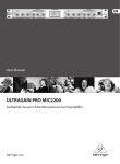
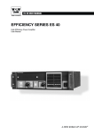
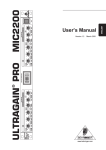
April 2001 www.behringer.com E ENGLISH XR4400 Version 1.1 ® MULTIGATE PRO Users Manual MULTIGATE PRO XR4400 SAFETY INSTRUCTIONS CAUTION: To reduce the risk of electric shock, do not remove the cover (or back). No user serviceable parts inside; refer servicing to qualified personnel. WARNING: To reduce the risk of fire or electric shock, do not expose this appliance to rain or moisture. This symbol, wherever it appears, alerts you to the presence of uninsulated dangerous voltage inside the enclosurevoltage that may be sufficient to constitute a risk of shock. This symbol, wherever it appears, alerts you to important operating and maintenance instructions in the accompanying literature. Read the manual. DETAILED SAFETY INSTRUCTIONS: All the safety and operation instructions should be read before the appliance is operated. Retain Instructions: The safety and operating instructions should be retained for future reference. Heed Warnings: All warnings on the appliance and in the operating instructions should be adhered to. Follow instructions: All operation and user instructions should be followed. Water and Moisture: The appliance should not be used near water (e.g. near a bathtub, washbowl, kitchen sink, laundry tub, in a wet basement, or near a swimming pool etc.). Ventilation: The appliance should be situated so that its location or position does not interfere with its proper ventilation. For example, the appliance should not be situated on a bed, sofa, rug, or similar surface that may block the ventilation openings, or placed in a built-in installation, such as a bookcase or cabinet that may impede the flow of air through the ventilation openings. Heat: The appliance should be situated away from heat sources such as radiators, heat registers, stoves, or other appliances (including amplifiers) that produce heat. Power Source: The appliance should be connected to a power supply only of the type described in the operating instructions or as marked on the appliance. Grounding or Polarization: Precautions should be taken so that the grounding or polarization means of an appliance is not defeated. Power-Cord Protection: Power supply cords should be routed so that they are not likely to be walked on or pinched by items placed upon or against them, paying particular attention to cords and plugs, convenience receptacles and the point where they exit from the appliance. Cleaning: The appliance should be cleaned only as recommended by the manufacturer. Non-use Periods: The power cord of the appliance should be unplugged from the outlet when left unused for a long period of time. Debris and Liquid Entry: Care should be taken that debris and/or liquids do not enter the enclosure through openings. Damage Requiring Service: The appliance should be serviced by qualified service personnel when: - The power supply cord or the plug has been damaged; or - Debris or liquid has entered the appliance; or - The appliance has been exposed to rain; or - The appliance does not appear to operate normally or exhibits a marked change in performance; or - The appliance has been dropped, or the enclosure damaged. Servicing: The user should not attempt to service the appliance beyond that which is described in the operating instructions. All other servicing should be referred to qualified service personnel. 2 MULTIGATE PRO XR4400 FOREWORD Dear Customer, Welcome to the team of MULTIGATE PRO users and thank you very much for expressing your confidence in BEHRINGER products by purchasing this unit. It is one of my most pleasant tasks to write this letter to you, because it is the culmination of many months of hard work delivered by our engineering team to reach a very ambitious goal: making an outstanding device better still. The MULTIGATE has for quite a long time been a standard tool used by numerous studios and PA rental companies. The task to improve one of our best-selling products certainly meant a great deal of responsibility, which we assumed by focusing on you, the discerning user and musician. It also meant a lot of work and night shifts to accomplish this goal. But it was fun, too. Developing a product usually brings a lot of people together, and what a great feeling it is when everybody who participated in such a project can be proud of what weve achieved. It is our philosophy to share our joy with you, because you are the most important member of the BEHRINGER family. With your highly competent suggestions for new products youve greatly contributed to shaping our company and making it successful. In return, we guarantee you uncompromising quality (manufactured under ISO9000 certified management system) as well as excellent technical and audio properties at an extremely favorable price. All of this will enable you to fully unfold your creativity without being hampered by budget constraints. We are often asked how we can make it to produce such high-grade devices at such unbelievably low prices. The answer is quite simple: its you, our customers! Many satisfied customers means large sales volumes enabling us to get better conditions of purchase for components, etc. Isnt it only fair to pass this benefit back to you? Because we know that your success is our success, too! I would like to thank all people whose help on Project MULTIGATE PRO has made it all possible. Everybody has made very personal contributions, starting from the designers of the unit via the many staff members in our company to you, the user of BEHRINGER products. My friends, its been worth the trouble! Thank you very much, Uli Behringer 3 MULTIGATE PRO XR4400 MULTIGATE PRO ® Audio interactive 4-channel expander/gate of the high-end class s UTR (Ultra Transient Response) selectable ultra-fast gate s IRC (Interactive Ratio Control) selectable ultra-smooth expander s Fully adjustable ratio control in expander mode s Fully adjustable attenuation control in gate mode s Independent hold/release controls for any envelope shaping s FlexLink system for flexible master/slave configurations s Filter monitor facility for monitoring the filter section s High-performance VCAs on all channels XR4400 s High-precision parametric filter for frequency selective operation s Ultra-low noise 4580 audio operational amplifiers for outstanding sound performance s Precise 8-segment metering for gain reduction s Accurate traffic light display for easy threshold setting s True RMS level detection for inaudible performance s Servo-balanced gold-plated XLR and 1/4" TRS inputs and outputs s High-quality detented potentiometers and illuminated switches s Manufactured under ISO9000 certified management system 4 MULTIGATE PRO XR4400 TABLE OF CONTENT 1. INTRODUCTION .....................................................................................................................6 1.1 Technical background ...................................................................................................................... 1.1.1 Noise as a physical phenomenon ......................................................................................... 1.1.2 What are audio dynamics? ................................................................................................... 1.1.3 Compressors/limiters ............................................................................................................ 1.1.4 Expanders/noise gates ......................................................................................................... 7 7 7 8 9 2. THE DESIGN CONCEPT ....................................................................................................... 9 2.1 High quality components and design ............................................................................................... 9 2.2 Inputs and outputs ........................................................................................................................ 10 2.2.1 Balanced inputs and outputs ............................................................................................... 10 3. INSTALLATION ..................................................................................................................... 10 3.1 Rack mounting .............................................................................................................................. 10 3.2 Mains voltage ................................................................................................................................ 10 3.3 Audio connections ........................................................................................................................ 10 4. CONTROLS .......................................................................................................................... 12 4.1 The front panel control elements ................................................................................................... 12 4.2 The rear panel elements ................................................................................................................ 13 5. TECHNICAL BACKGROUND .............................................................................................. 14 5.1 EXPANDER mode ......................................................................................................................... 5.2 Interactive control functions ........................................................................................................... 5.2.1 THRESHOLD control .......................................................................................................... 5.2.2 Attack, release and hold times ........................................................................................... 5.2.3 IAC circuit (Interactive Attack Control) ................................................................................. 5.2.4 RANGE function ................................................................................................................. 5.2.5 IRC circuit (Interactive Ratio Control) ................................................................................... 5.2.6 RATIO function .................................................................................................................... 5.3 FLEXLINK function ........................................................................................................................ 5.4 The SIDECHAIN filter .................................................................................................................... 5.4.1 The MONITOR function ....................................................................................................... 14 14 14 15 15 15 16 16 16 17 17 6. APPLICATIONS ..................................................................................................................... 17 6.1 Basic setting ................................................................................................................................. 6.1.1 The gate function ................................................................................................................ 6.1.2 The expander function ......................................................................................................... 6.2 Proper positioning of microphones ................................................................................................ 6.3 Applications .................................................................................................................................. 6.3.1 Suppressing crosstalk in multi-track applications ................................................................ 6.3.2 Reducing crosstalk in stage microphones ........................................................................... 6.3.3 Reducing feedback in stage microphones ........................................................................... 17 17 19 19 19 19 20 20 7. SPECIFICATIONS .................................................................................................................. 21 8. WARRANTY ........................................................................................................................... 22 5 MULTIGATE PRO XR4400 1. INTRODUCTION With the BEHRINGER MULTIGATE PRO you purchased a dynamics processor of the high-end class designed to meet highest requirements: professional recording, broadcast and television studios, CD and digital production facilities, etc. Its complete range of features and innovative circuit topology make the MULTIGATE PRO an all-purpose device for reducing noise in audio recordings, for automatically muting stage mics, expanding the dynamic range of compressed recordings, improving the signal-to-noise ratio of noisy communications systems and for producing special effects, etc. Future-oriented BEHRINGER technology Our MULTIGATE range of devices has been a hit ever since we introduced our first model several years ago. This expander/gate is based on many years of experience and findings in psychoacoustics and is used throughout the world in renowned studios, sound reinforcement systems as well as in broadcast and television studios. It was a real challenge to improve the well-known MULTIGATE even further, and we are proud of our success. Compared to its predecessor models, the MULTIGATE PRO not only has additional features, but also comes with dramatically improved functionalities. For example, it now has a parametric filter enabling you to accurately set the trigger frequencies, while the FlexLink system allows for great flexibility when linking the devices individual channels in a master/slave configuration. Basically, quadruple gates are not a new invention. However, packing four simple noise gates into one enclosures usually means a compromise in terms of ease of operation and functionality. Too many control elements make such a device impossible to handle, and if you sacrifice crucial functions for the sake of easy operation, the range of useful applications is restricted considerably. The BEHRINGER MULTIGATE PRO is a quadruple expander/gate with a maximum of functionalities and can still be operated conveniently. Interactive functions make it easy and efficient to specifically process any kind of program material, while the need for adjustment work has been reduced drastically. Each of the MULTIGATE PROs four sections comprises an ultra-fast gate, a program-dependent expander, a filter section and high-precision meters indicating both threshold point and gain reduction. The IAC circuit (Interactive Attack Control) One of the MULTIGATE PROs most outstanding features is the program-dependent control of attack times. The new IAC circuit (Interactive Attack Control) analyzes the program material to calculate the attack time by way of interaction, so that the hold/release process is triggered automatically depending on the program, which is why the MULTIGATE PRO does not need a dedicated attack control. Switchable gate/expander function Another highlight of the MULTIGATE PRO is the switchable operating mode of gate and expander. With the MODE function off, the MULTIGATE PRO works in gate mode using an extremely fast attack time to gate all kinds of drum and synthesizer sounds, without cutting their percussive edge. In expander mode the device analyzes the shape and dynamic contents of the input signal to calculate the control time parameters. It thus works as an interactive expander that adapts automatically to the program signal. The result: guitar sounds, vocals and complex mix signals can be cleaned without audible clicks, breathing or other detrimental effects. Additionally, you can freely expand any type of program material in its dynamic range. Side-chain filter section When several microphones are used, for example to pick up a drum set, crosstalk between microphones can lead to unwanted triggering of the gate. The built-in parametric sidechain filter of the MULTIGATE PRO allows the user to accurately select the frequencies causing the trouble, so that the device responds to these frequencies only. The monitor function can be used to pre-monitor the filter, making it easier to adapt the circuitry to the acoustic properties of the program material. FlexLink system An innovative couple function gives you great flexibility to synchronize the expander/gate sections in a master/ slave configuration. 6 1. INTRODUCTION MULTIGATE PRO XR4400 + The following operational manual will introduce you to the BEHRINGER MULTIGATE PRO and its various functions. After reading the manual carefully, make sure it is always on hand for future reference. 1.1 Technical background By employing current modern analog technology it is possible to manufacture audio equipment with a dynamic range of up to 130 dB. In contrast to analog techniques, the dynamic range of digital equipment is approximately 25 dB less. With conventional record and tape recorder technology, as well as broadcasting, this value is further reduced. Generally, dynamic restrictions are due to noisy storage in transmission media and also the maximum headroom of these systems. 1.1.1 Noise as a physical phenomenon All electrical components produce a certain level of inherent noise. Current flowing through a conductor leads to uncontrolled random electron movements. For statistical reasons, this produces frequencies within the whole audio spectrum. If these currents are highly amplified, the result will be perceived as noise. Since all frequencies are equally affected, we term this white noise. It is fairly obvious that electronics cannot function without components. Even if special low-noise components are used, a certain degree of basic noise cannot be avoided. This effect is similar when replaying a tape. The non-directional magnetic particles passing the replay head can also cause uncontrolled currents and voltages. The resulting sound of the various frequencies is heard as noise. Even the best possible tape biasing can only provide signal-to-noise ratios of about 70 dB, which is not acceptable today since the demands of listeners have increased. Due to the laws of physics, improving the design of the magnetic carrier is impossible using conventional means. 1.1.2 What are audio dynamics? A remarkable feature of the human ear is that it can detect the most wide ranging amplitude changesfrom the slightest whisper to the deafening roar of a jet-plane. If one tried to record or reproduce this wide spectrum of sound with the help of amplifiers, cassette recorders, records or even digital recorders (CD, DAT etc.), one would immediately be restricted by the physical limitations of electronic and acoustic sound reproduction technology. The usable dynamic range of electro-acoustic equipment is limited as much at the low end as at the high end. The thermal noise of the electrons in the components results in an audible basic noise floor and thus represents the bottom limit of the transmission range. The upper limit is determined by the levels of the internal operating voltages; if they are exceeded, audible signal distortion is the result. Although in theory, the usable dynamic range sits between these two limits, it is considerably smaller in practice, since a certain reserve must be maintained to avoid distortion of the audio signal if sudden level peaks occur. Technically speaking, we refer to this reserve as headroomusually this is about 10 - 20 dB. A reduction of the operating level would allow for greater headroom, i.e. the risk of signal distortion due to level peaks would be reduced. However, at the same time, the basic noise floor of the program material would be increased considerably. 1. INTRODUCTION 7 MULTIGATE PRO XR4400 P/dB 140 120 Cassette Recorder Radio Ear 40 Tape Recorder 60 Power Amplifier 80 Microphone Amplifier 100 Fig. 1.1: The dynamic range capabilities of various devices It is therefore useful to keep the operating level as high as possible without risking signal distortion in order to achieve optimum transmission quality. It is possible to further improve the transmission quality by constantly monitoring the program material with the aid of a volume fader, which manually levels the material. During low passages the gain is increased, during loud passages the gain is reduced. Of course it is fairly obvious that this kind of manual control is rather restrictive; it is difficult to detect signal peaks and it is almost impossible to level them out. Manual control is simply not fast enough to be satisfactory. P/dB Clipping +20 0 Headroom Operating level -20 -40 Effective SNR -60 -80 Noise floor t Fig. 1.2: The interactive relationship between the operating level and the headroom The need therefore arises for a fast acting automatic gain control system which will constantly monitor the signals and which will always adjust the gain to maximize the signal-to-noise ratio without incurring signal distortion. This device is called a compressor or limiter. 1.1.3 Compressors/limiters By measuring the dynamic range of musical instruments in live recording situations, you will find that extreme amplitudes occur which often lead to overload in subsequent signal processing equipment. Especially in broadcasting and record cutting techniques, these signal peaks can lead to heavy distortion. To avoid this kind 8 1. INTRODUCTION MULTIGATE PRO XR4400 of distortion or, for example, to avoid loudspeakers being damaged by overload, Compressors or Limiters are used. The principal function used in these devices is dependent on an automatic gain control as mentioned in the previous section, which reduces the amplitude of loud passages and therefore restricts the original dynamics to a desired range. This application is particularly useful in microphone recording techniques, to compensate for level changes which are caused by varying microphone distances. Although compressors and limiters perform similar tasks, one essential point makes them different: Limiters abruptly limit the signal above a certain level, while compressors control the signal gently over a wider range. A limiter continuously monitors the signal and intervenes as soon as the level exceeds a user-adjustable threshold. Any signal exceeding this threshold will be immediately returned to the adjusted level. A compressor also monitors the program material continuously and has a certain threshold level. With compression, in contrast to the action of a limiter, signals are not reduced in level abruptly once the threshold has been exceeded, but are returned to the threshold gradually. The signal is reduced in gain, relative to the amount the signal exceeds this point. Generally, threshold levels for compressors are set below the normal operating level to allow for the upper dynamics to be musically compressed. For limiters, the threshold point is set above the normal operating level in order to provide reliable signal limiting, to protect subsequent equipment from signal overload. 1.1.4 Expanders/noise gates Audio, in general, is only as good as the source from which it was derived. The dynamic range of signals will often be restricted by noise. Synthesizers, effects devices, guitar pickups, amplifiers etc. generally produce a high level of noise, hum or other ambient background hiss, which can disturb the quality of the program material. Normally these noises are inaudible if the level of the desired signal lies significantly above the level of the noise. This perception by the ear is based on the masking effect: noise will be masked and thus becomes inaudible as soon as considerably louder sound signals in the same frequency band are added. Nevertheless, the further the level that the desired signal decreases, the more the noise floor becomes a disturbing factor. Expanders or noise gates offer a solution for this problem: these devices attenuate signals when their amplitudes drop, thereby fading out the background noise. Relying on this method, gain controlling amplifiers, like expanders, can extend the dynamic range of a signal and are therefore the opposite of a compressor. In practice, it is shown that an expansion over the entire dynamic range is not desired. With an expansion ratio of 1:5 and a processed dynamic range of 30 dB, an output dynamic range of 150 dB will be the result, exceeding all subsequent signal processors, as well as human hearing. Therefore, the amplitude control is restricted to signals whose levels are below a certain threshold. Signals above this threshold pass through the unit unchanged. Due to the continuous attenuation of the signals below this threshold, this kind of expansion is termed downward expansion. The noise gate is the simplest form of an expander: in contrast to the expander, which continuously attenuates a signal below the threshold, the noise gate cuts off the signal abruptly. In most applications this method is not very useful, since the on/off transition is too drastic. The onset of a simple gate function appears very obvious and unnatural. To achieve inaudible processing of the program material, it is necessary to be able to control the signals envelope parameters. 2. THE DESIGN CONCEPT 2.1 High quality components and design The philosophy behind BEHRINGER products guarantees a no-compromise circuit design and employs the best choice of components. The operational amplifiers NJM4580 which are used in the MULTIGATE PRO, are exceptional. They boast extreme linearity and very low distortion characteristics. To complement this design the choice of components includes high tolerance resistors and capacitors, detent potentiometers and several other stringently selected elements. 2. THE DESIGN CONCEPT 9 MULTIGATE PRO XR4400 For the first time, the MULTIGATE PRO XR4400 uses SMD technology (Surface Mounted Device). These sub-miniature components known from aerospace technology allow for an extreme packing density, plus the units reliability could be improved. Additionally, the unit is manufactured in compliance with a ISO9000 certified management system. 2.2 Inputs and outputs 2.2.1 Balanced inputs and outputs As standard, the BEHRINGER MULTIGATE PRO is installed with electronically servo-balanced inputs and outputs. The new circuit design features automatic hum and noise reduction for balanced signals and thus allows for trouble-free operation, even at high operating levels. Externally induced mains hum etc. will be effectively suppressed. The automatic servo-function recognizes the presence of unbalanced connectors and adjusts the nominal level internally to avoid level differences between the input and output signals (correction 6 dB). 3. INSTALLATION Your BEHRINGER MULTIGATE PRO was carefully packed in the factory and the packaging was designed to protect the unit from rough handling. Nevertheless, we recommend that you carefully examine the packaging and ist contents for any signs of physical damage, which may have occurred in transit. + If the unit is damaged, please do not return it to us, but notify your dealer and the shipping company immediately, otherwise claims for damage or replacement may not be granted. Shipping claims must be made by the consignee. Please take the time to complete and return the warranty card within 14 days of the date of purchase, otherwise you will lose the right to the extended warranty. Or just use our online-registration (www.behringer.com). 3.1 Rack mounting The BEHRINGER MULTIGATE PRO fits into one standard 19" rack unit of space (1 ¾"). Please allow at least an additional 4" depth for the connectors on the back panel. Be sure that there is enough air space around the unit for cooling and please do not place the MULTIGATE PRO on high temperature devices such as power amplifiers etc. to avoid overheating. 3.2 Mains voltage Before you connect your MULTIGATE PRO to the mains, please make sure that your local voltage matches the voltage required by the unit! The fuse holder on the female mains connector has 3 triangular markers, with two of these triangles opposing each other. Your MULTIGATE RPO is set to the operating voltage printed next to these markers, and can be set to another voltage by turning the fuse holder by 180°. CAUTION: this instruction does not apply to export models exclusively designed, e.g. for 115 V operation! 3.3 Audio connections The audio inputs and outputs on the BEHRINGER MULTIGATE PRO are fully balanced. If possible, connect the unit to other devices in a balanced configuration to allow for maximum interference immunity. + 10 Please ensure that only qualified persons install and operate the MULTIGATE PRO. During installation and operation the user must have sufficient electrical contact to earth. Electrostatic charges might affect the operation of the MULTIGATE PRO! 3. INSTALLATION MULTIGATE PRO XR4400 Output Cable Input Ground Pin 1 2 1 1 Shield (+) Signal + Hum (-) Signal + Hum Pin 2 = (+) Signal 3 2 Positive (+)Hum + Signal Negative (-)Hum + Signal 3 Pin 3 = (-) Signal 2 x Signal = Signal + 6 dB RFI and Hum Fig. 3.1: Compensation of interference with balanced connections Unbalanced use of mono 1/4" jack plugs Balanced use of stereo 1/4" jack plugs Tip = Signal Tip = hot (+ve) Ring = cold (-ve) Sleeve = Ground / Shield Sleeve = Ground / Shield Tip Tip Sleeve Ring Sleeve Strain relief clamp Strain relief clamp For connection of balanced and unbalanced plugs, ring and sleeve have to be bridged at the stereo plug. Balanced use with XLR connectors 2 1 3 1 = Ground / Shield 2 = hot (+ve) 3 = cold (-ve) Input 1 2 3 Output For unbalanced use pin 1 and pin 3 have to be bridged Fig. 3.2: Different plug types + Never use unbalanced XLR connections with microphone cables, as this would short-circuit any phantom power transmitted over these cables! 3. INSTALLATION 11 MULTIGATE PRO XR4400 4. CONTROLS Fig. 4.1: MULTIGATE PRO front panel The BEHRINGER MULTIGATE PRO has four channels. Each of these channels is equipped with 3 or 4 pushbuttons, 6 rotary controls and 11 LEDs. 4.1 The front panel control elements Fig. 4.2: Control elements on the front panel 1 The FREQUENCY control determines the lower limit frequency of the sidechain filter, and covers a range from 100 Hz to 10 kHz. 2 The BANDWIDTH control determines the slope or bandwidth of the sidechain filter. The bandwidth can be set within a range from 2.3 to 0.7 octaves, so as to realize even extremely narrow-band filter settings. 3 The FILTER control activates the parametric sidechain filter. To edit this filter there you can use the frequency and BW control. 4 The MONITOR switch establishes a link between the sidechain control signal and the audio output. As it also mutes the audio input signal the user can pre-monitor the parametric filter output, which makes it easier to tune the filter by ear. + 5 + 12 Please note that the MONITOR switch disables the channels audio signal. Use the THRESHOLD control to set the threshold point of the expander/gate function within a range from BYPASS to +10 dBu. Signals below the threshold are reduced in level. When the signal drops below the threshold, the hold/release function starts reducing the signal to a level adjustable with the RANGE/RATIO control. Please note that the MULTIGATE PRO enters bypass mode, when the THRESHOLD control is set to its left stop position, i.e. all processing functions are disabled and the signal is routed directly from the input to the output. 4. CONTROLS MULTIGATE PRO XR4400 6 This traffic light LED chain shows the current operating mode of the unit: the + LED (red) indicates that the sidechain signal is below the threshold, the HOLD LED (yellow) informs you that the hold circuit/release process has been activated, while the - LED (green) shows that the sidechain signal is above the threshold. 7 The HOLD control determines the delay applied to the starting point of the release process, after the signal has dropped below the threshold. The setting range is 0 to 4 seconds. + 8 + The HOLD control is enabled in GATE mode only! The RELEASE control determines the time of the release process. This process begins after the end of the hold phase and ends when the gain reduction adjusted with the RANGE control is achieved. The setting range of the RELEASE control is from 0.05 to 4 seconds. The RELEASE control is enabled in GATE mode only! 9 The MODE switch is used to set the operating mode of the respective channel. When the switch is out, the corresponding section works as an ultra-fast gate. In this mode, even percussive signals can be processed without any signal loss. With the MODE function on, the IRC expander (Interactive Ratio Control) is activated. This interactive control function allows for the program-dependent expansion of complex signals. Both the attack time and the fade-out characteristics (ratio) vary depending on the program material. The agreeable results of this automatic process are less critical adjustment work and inaudible expansion of the program material. 10 The RANGE/RATIO control performs a dual function: depending on the position of the MODE switch (i.e. depending on the operating mode of the unit: gate or expander), the RANGE/RATIO control determines the maximum amount of gain reduction or the expansion curve. In gate mode, this control adjusts the RANGE determining the amount of maximum gain reduction from 0 dB to -80 dB. In expander mode, it works as a RATIO control setting the expansion ratio. The ratio function determines the input vs. output level ratio, for all signals below the threshold. The setting range is from 1:1 to 1:4. 11 The 8-digit GAIN REDUCTION meter informs you about the current amount of gain reduction within a range from 1 to 40 dB. 12 When you press the COUPLE switch, this channel is automatically configured as a slave channel. Its left neighbor becomes the master now controlling both channels in all their parameters. 4.2 The rear panel elements Fig. 4.3: Rear panel elements 13 FUSE HOLDER / VOLTAGE SELECTOR. Please make sure that your local voltage matches the voltage indicated on the unit, before you attempt to connect and operate the MULTIGATE PRO. Blown fuses may only be replaced by fuses of the same type and rating. 14 MAINS CONNECTION. Use the enclosed power cord to connect the unit to the mains. Please also note the instructions given in the INSTALLATION chapter. 15 AUDIO IN. These are the audio inputs of your MULTIGATE PRO, available both as balanced 6.3 mm jack and XLR connectors. 16 AUDIO OUT. These are the audio outputs of your MULTIGATE PRO. Matching phone jack and XLR connectors are wired in parallel. 4. CONTROLS 13 MULTIGATE PRO XR4400 5. TECHNICAL BACKGROUND 5.1 EXPANDER mode As already described, a so-called downward expander automatically reduces the overall level of all signals that drop below an adjustable threshold, and thus expands the dynamic range of the program material. In other words, an expander is the opposite of a compressor. Expanders usually work with a relatively flat ratio curve to fade out the signal smoothly. Noise gates are a special form of expander using a much steeper ratio curve to abruptly cut the signal when it drops below the threshold. As expanders and gates are quite similar in what they do the following description of expanders and their functionalities also applies to noise gates. Fig. 6.1: Expander mode 5.2 Interactive control functions Like the COMPOSER, INTELLIGATE, MULTICOM, and others, the MULTIGATE PRO uses the newly developed INTERACTIVE principle based on a chain of intelligent control functions. For example, the IRC expander (Interactive Ratio Control) does not use a fixed ratio curve but varies this curve depending on the input level and the setting of the THRESHOLD control. The following chapter describes the interactive control functions in full detail: 5.2.1 THRESHOLD control The THRESHOLD control determines the threshold point and disables the respective channel. As it covers a very wide setting range it can be easily adapted to any operating level: Input levels above the adjusted threshold point pass the circuit unprocessed. However, as soon as the input signal drops below the threshold, dynamics processing sets on. Simple noise gates usually have a control to set the switch-on and switch-off thresholds, but must perform their task without any dedicated control elements that allow for varying the envelopes. The BEHRINGER MULTIGATE PRO, however, is equipped with all necessary control options. The following section makes clear why it is so important to be able to adjust these parameters. 14 5. TECHNICAL BACKGROUND MULTIGATE PRO XR4400 5.2.2 Attack, release and hold times The BEHRINGER MULTIGATE PRO is equipped with a MODE switch as well as a HOLD and RELEASE control to adjust the time-domain parameters that determine the so-called envelope: Fig. 6.2: Principle of envelope function Attack time The quality of an expander/gate is largely determined by the speed of its attack function (rise time). This parameter defines the time the expander needs after the signal has passed the threshold to recover from the applied gain reduction, i.e. to reverse the control process. Extremely short transients (level peaks) such as hand claps and percussive instruments, etc. require an extremely short attack time to prevent the expander from cutting the signal flanks and thus deteriorating the sound. The new BEHRINGER-developed UTR circuit (Ultra Transient Response) in combination with a high-grade VCA allows for an extremely short response time in gate mode, without audible switching noise as it is generated by many conventional designs. Release time Another important parameter is the release time, as it determines the time the gate needs to reduce the signal level by a certain amount, after the signal has dropped below the threshold. Hold time The hold-time parameter enables you to delay the starting point of the release process. In particular, when processing frequently interrupted signals such as vocals, an additional hold-time parameter is indispensable to prevent the gate from switching off and back on during signal pauses. 5.2.3 IAC circuit (Interactive Attack Control) The MULTIGATE PRO features an IAC circuit (Interactive Attack Control) which analyzes the program material to calculate the attack time by way of interaction, so that the hold/release process is triggered automatically depending on the program material. This is the reason why the MULTIGATE PRO does not need a dedicated attack control. 5.2.4 RANGE function On the MULTIGATE PRO the dynamic processing is controlled by a high-grade VCA with a working range of more than 100 dB, i.e. the input signal can be reduced in level by as much as 100 dB. For most applications, however, it is neither desirable nor necessary to cut the signal completely after it has dropped below the threshold. In particular, when processing signals with lots of background noise, this would result in abrupt and audible control processes that are less likely to enhance the overall sound quality. For this reason, the MULTIGATE PRO is equipped with a RANGE control that allows you to limit the maximum 5. TECHNICAL BACKGROUND 15 MULTIGATE PRO XR4400 gain reduction applied. Thus, you can use smaller amounts of gain reduction making it possible to retain the natural sound of the program materialin particular, with signals that contain plenty of interference noise. 5.2.5 IRC circuit (Interactive Ratio Control) In conventional expanders the control processes cut the signal abruptly below the threshold, which usually leads to less satisfying results, because the onset of the control function becomes audible. When inaudible expansion is needed, it is therefore better to use a soft-knee characteristic around the threshold point that allows for a smoother transition. The BEHRINGER MULTIGATE PRO uses the newly developed IRC expander (Interactive Ratio Control) whose attack time and ratio characteristics vary automatically depending on the program material. The IRC expander is switched on with the MODE switch. Low ratios and hence subtle expansion produce a smooth transition, while higher ratios and heavy expansion result in a steeper transition between the characteristic curves. This so-called interactive, i.e. nonlinear IRC characteristic is perfectly adapted to human hearing: critical wanted signals around the threshold point are less expanded, while interference signals with lower levels (e.g. background noise) are processed and faded out with a higher expansion ratio. Fig. 6.3: IRC characteristic curve The result is an expansion process that is less difficult to adjust and more tolerant towards wanted signals whose levels are only slightly above the level of the background noise. 5.2.6 RATIO function The ratio of the input-level-change vs. output-level-change after the onset of the control process, i.e. after the signal has dropped below the threshold, is called expansion ratio and can be set with the RATIO control. RATIO settings from 1:1.2 through 1:4 give you smooth and exactly dosed downward expansion. The RATIO scale printed on the front panel indicates the expansion ratio in decibels, i.e. it shows you the decibels by which the output signal is cut for each reduction by one dB of the input signal. With a 1:1 ratio the output signal level is the same as the input signal level, i.e. there is no signal change. A ratio of 1:2 means that the output signal is reduced by 2 dB when the input signal drops below the threshold by 1 dB. Accordingly, with a ratio of 1:4, the output signal is cut in level by 4 dB when the input signal is 1 dB below the threshold. 5.3 FLEXLINK function The four channels of the MULTIGATE PRO can be operated both independently of each other and in couple mode. In particular, when you record a choir it will be useful to couple the individual microphone channels. For example, when all microphones are controlled by one singer, all vocals start and stop precisely at the same 16 5. TECHNICAL BACKGROUND 17 MULTIGATE PRO XR4400 point of time. Also when synchronizing several instruments, inaccurate entries of individual musicians can be avoided. To expand phase-coherent stereo signals (i.e. signals having the same phase), it is imperative that the control processes be triggered simultaneously in both channels. Due to the differences in perceived loudness between the left and right channels, unwanted shifts with reference to the stereo basis would be produced. The innovative FlexLink function implemented in the MULTIGATE PRO allows for a variety of couple options. For example, when you press the COUPLE switch of channel 3, this channel is automatically configured as a slave channel, while its neighborchannel 2becomes the master now controlling both channels in all their parameters. Activating the COUPLE switch automatically disables all controls and switches of channel 3 (except for the MONITOR switch). Now, the controls of channel 2 take over full control of channel 3. Similar to a stereo fader, both channels work in sync. To control channels 2 and 3 from channel 1, simply press the COUPLE switches of channel 2 and 3. 5.4 The SIDECHAIN filter Each channel has a parametric filter whose frequency and quality (bandwidth) can be set precisely. This tunable filter allows you to select and fade out specific frequencies that would otherwise lead to unwanted triggering of the expander circuit. 5.4.1 The MONITOR function This switch links the sidechain control signal with the audio output, while muting the audio input signal, so that you can pre-monitor the filter output and tune the parametric filter. + Please note that the channels entire processing functions will be disabled when you press the MONITOR switch. 6. APPLICATIONS This chapter describes a few typical applications of the BEHRINGER MULTIGATE PRO. Starting from the basic setting shown below you can find solutions to most dynamics-based problems. Please take your time to study the following application examples thoroughly, so as to be able to fully exploit the variety of features your MULTIGATE PRO offers. Basically, the BEHRINGER MULTIGATE PRO can be used in three areas of application: 1. Eliminating interference noise and suppressing crosstalk in multi-channel or multi-microphone configurations. 2. Expanding the dynamic range of compressed program material, refreshing sampled sounds and creating special effects and sounds. 3. Using the MULTIGATE PRO as a de-esser and to specifically eliminate interference noise from recordings as well as to reduce the risk of feedback in live situations. 6.1 Basic setting Understandably, there is no standard setting that suits all kinds of applications. Rather, the controls and switches must be set specifically for the application on hand. However, by studying the following practiceoriented descriptions of typical applications you will soon develop a feel for how the various functions work: 6.1.1 The gate function Gating is a so-called high ratio expander function and represents the simplest function of the BEHRINGER MULTIGATE PRO. When the expander is operated with maximum gain reduction (RANGE control fully to the left), it works in hard gating mode. The gate function is used to automatically mute single channels in 6. APPLICATIONS 17 MULTIGATE PRO XR4400 multitrack mixdowns, stage microphones currently not in use and to suppress background noise and crosstalk in multi-track recordings. In particular, when processing percussive instrument the use of the hard gating function is recommended. A few examples show you how to do it: Electric signals from percussion instruments have a very short rise time. The time between single hits on the instruments is normally filled up with noise produced by adjacent instruments or room reverb, which makes it difficult or even impossible to separate microphones acoustically. This unwanted crosstalk effect can be accurately eliminated with the MULTIGATE PRO. Adjust all controls and switches to the following basic settings: Control elements Position MONITOR switch OUT SC FILTER switch OUT THRESHOLD switch fully clockwise HOLD control center position RELEASE control center position MODE switch GATE RANGE/RATIO control fully counter-clockwise Tab. 6.1: Initial settings of the MULTIGATE PRO THRESHOLD control Now turn the THRESHOLD control counter-clockwise until the lowest signal delivered by the instrument you wish to record triggers the expander and is reproduced without any sound deterioration. The + LED lights up as soon as the expander is triggered. When everythings set up properly, you will hear the instrument clearly stand out against the overall sound image. HOLD control (available in GATE mode only) The program material (e.g. speech/vocal recordings) often contains many and sometimes very short signal pauses, which could switch the gate off and back on over and again. The hold function prevents this annoying flutter effect known from conventional designs, simply by delaying the starting point of the release process. Thus, the gate remains on during short signal pauses. When the adjusted hold time has expired, the gate closes the audio channel depending on how the release function has been set. + Please note that this control can be used in gate mode only! RELEASE control (available in GATE mode only) Many percussion instruments have long decay times (e.g. cymbals). As the release time can be adjusted on the MULTIGATE PRO, the device allows you to follow the decay curve of the instrument so that its overall sound character will be retained. In this way, you can avoid that short release times affect the natural decay phase of the instrument or its corresponding reverb ambiance. Slowly decaying or heavily reverberated signals are best processed with long release times. You will note that with most drum sounds a short release time should be used for the sake of acoustic separation, while longer release times are usually better for cymbals and tom-toms. Once all control elements have been set properly, your percussion sounds will be dry, powerful and acoustically well-defined. + Please note that this control can be used in gate mode only! RANGE control The RANGE control determines the amount of maximum attenuation of the audio signal. When you process instruments with long decay times, it will be helpful to set the RANGE control to mid-travel position, so that the 18 6. APPLICATIONS MULTIGATE PRO XR4400 signal will not be suppressed completely. Although the MULTIGATE PRO allows for a maximum gain reduction of 80 dB, it is usually not useful to reduce the signal level by this maximum amount. In particular, with highly noise-affected signals we recommend that you use a signal attenuation of not more than 10 to 20 dB, so that the onset of the gate function will not become too obvious. 6.1.2 The expander function In contrast to the gate function, the expander triggers a continuous attenuation of the signal, as soon as it has dropped below the threshold. RATIO control With the MODE switch in, the MULTIGATE PRO works as an interactive expander. The RATIO control determines the expansion curve. For example, when a piece of music was highly compressed during the recording session, the lost dynamics can be restored through complementary expansion. With a bit of feeling you can set the following controls by ear so that the original dynamics (prior to the compression process) will be restored. We recommend that you set the RATIO control to about 1:1.2 through 1:2 to allow for a smooth expansion curve, and that you adjust the THRESHOLD control so that the entire dynamic range of the music piece will be below the threshold point. Now set the THRESHOLD control so that only the loudest passages of the program material surpass the threshold point (- LED flashes). In the same way, you can artificially expand the dynamic range of any instrument. In particular, when processing sampled sounds, expansion can produce nice results, because samplers usually have a highly limited dynamic range. When processing percussion sounds (e.g. snare drum) you can use downward expansion to create interesting effects, for example, by setting the threshold to about mid-position, so that only the lower part of the dynamics will be processed: the signal decays unchanged until the adjusted threshold is reached, and any subsequent signal portions are faded out with increasing attenuation. 6.2 Proper positioning of microphones The main task of an expander is to separate unwanted background noise from the actual signal and to eliminate this noise inaudibly. Understandably, there must be a minimum difference in the levels of wanted signal and interference signal, so as to be able to define a threshold point for the expander. However, the optimum operation of an expander depends on the proper choice and positioning of the microphones: Be extremely careful when instruments with high-frequency portions are played to the sides or back of a microphone with a cardioid polar pattern. Most room microphones suffer from a deterioration of their directivity when picking up high frequencies. For example, with a sensitivity difference of not more than 2-3 dB around 5-10 kHz between the main and lateral axes, cymbals can produce enormous crosstalk in tom-tom microphones, or the hi-hats can mask the sound of the snare drum. You should make optimum use of the specific directivity of a microphone to acoustically separate other instruments as perfectly as possible. Do as best as you can to separate the sound sources acoustically simply by positioning the microphones correctly. Yet, in some applications even perfectly positioned microphones might not produce satisfying results. With its side-chain function the BEHRINGER MULTIGATE PRO gives you the option of frequency-selective expansion and thus another aid to ensure perfect acoustic separation of the sound sources. 6.3 Applications 6.3.1 Suppressing crosstalk in multi-track applications One of the most frequent applications of an expander/gate is the elimination of unwanted crosstalk between single channels during recording or playback. In particular, when recording acoustic drum sounds, this type of application is frequently used, because here several microphones closely positioned next to each other are used. 6. APPLICATIONS 19 MULTIGATE PRO XR4400 The high sound pressure levels of the individual instruments lead to crosstalk in adjacent microphones. Frequency cancellations and a non-defined sound (comb filter effect) are the result. It has proven wise to use a separate microphone for each drum instrument and to gate each microphone channel. Insert the BEHRINGER MULTIGATE PRO into the recording channel of the snare drum, for example, and adjust the device so that it responds only to hits on the snare drum. Each single microphone should be optimally positioned before, and the threshold of the respective channel should be set so that the drum sound can be separated cleanly, just as if the instrument were played alone. 6.3.2 Reducing crosstalk in stage microphones The MULTIGATE PRO can be used in a variety of live/stage and multimicrophone applications: a moderately set expander can effectively suppress background noise, or the noise build-up that is typically produced by compressors as well as crosstalk between microphones, etc. without causing other unwanted side effects. Typically, an expander can be used to process vocal tracks. Particularly when using a compressor, the distance between singer and microphone is of crucial importance: As the distance increases, more and more disturbing background noise is picked up. You should therefore use the expander function to fade out unwanted interference noise inaudibly during signal pauses. In live situations you can eliminate bleeding, for instance, from drum to piano tracks, or clean your recordings from other acoustic pollution. If you do not have enough microphones (or MULTIGATE PRO!) to record each instrument separately, try forming so-called subgroups: comprise the snare and middle toms, side toms, kick drum and cymbals in one group using the subgroup facilities on your mixing console. The goal is to position the groups microphones and to adjust the expander so that with each hit on a specific instrument only one microphone opens, thus transmitting only one specific instrument, while the remaining microphones remain muted. 6.3.3 Reducing feedback in stage microphones As soon as a singer sings into his/her microphone, background noise is masked and thus not perceived. During signal pauses, however, the microphone picks up the noise from PA and monitor speakers, which can lead to torturing feedback. By inserting the MULTIGATE PRO into the vocal channel and by adjusting it to mute the microphone when it is not in use, you can reduce the risk of feedback in this particular channel. Basically, this configuration should be used for all stage microphones. 20 7. SPECIFICATIONS MULTIGATE PRO XR4400 7. SPECIFICATIONS AUDIO INPUT Connectors Type Impedance Max. Input Level CMRR XLR and 1/4" jack RF filtered, servo-balanced input 50 kOhm balanced, 25 kOhm unbalanced +21 dBu balanced and unbalanced typ. 40 dB, >55 dB @ 1 kHz AUDIO OUTPUT Connectors Type Impedance Max. Output Level XLR and 1/4" jack Electronically servo-balanced output stage 60 Ohms balanced, 30 Ohm unbalanced +21 dBu, +20 dBm balanced and unbalanced SYSTEM SPECIFICATIONS Frequency Response Noise THD IMD Crosstalk 18 Hz to 30 kHz, +/- 3 dB >95 dBu, unweighted, 22 Hz to 22 kHz 0.008 % typ. @ +4 dBu, 1 kHz, Gain 1 0.01 % typ. SMPTE <-100 dB, 22 Hz to 22 kHz GATE SECTION Type Threshold Attack Hold Release Range UTR (Ultra Transient Response) gate variable (BYPASS to +10 dBu) program dependent variable (0 to 4 sec) variable (50 ms to 4 sec) variable (0 to -80 dB) EXPANDER SECTION Type Attack Ratio IRC (Interactive Ratio Control) expander program dependent variable (1:1 to 1:4) SIDE-CHAIN FILTER Frequency BW (Bandwidth) variable (100 Hz to 10 kHz) variable (2.3 to 0.7 oct.) FUNCTION SWITCHES Monitor Filter Mode Couple monitors the side-chain key signal activates the side-chain filter gate/expander switch activates the FlexLink function INDICATORS + indicator signal is below threshold Hold indicator signal reaches the threshold - indicator signal is above threshold Gain Reduction 8-segment LED display: 1/3/6/10/15/20/30/40 dB LED indicator for each function switch POWER SUPPLY Mains Voltages Power Consumption Fuse Mains Connection PHYSICAL Dimension Net Weight Shipping Weight USA/Canada 120 V ~, 60 Hz U.K./Australia 240 V ~, 50 Hz Europe 230 V ~, 50 Hz General Export Model 100 - 120 V ~, 200 - 240 V ~, 50 - 60 Hz max. 20 Watts 100 - 120 V ~: T 630 mA H 200 - 240 V ~: T 315 mA H Standard IEC receptacle 1 ¾" (44.5 mm) * 19" (482.6 mm) * 8 ½" (217 mm) approx. 2.5 kg approx. 3.5 kg BEHRINGER is constantly striving to maintain the highest professional standards. As a result of these efforts, modifications may be made from time to time to existing products without prior notice. Specifications and appearance may differ from those listed or shown. 7. SPECIFICATIONS 21 MULTIGATE PRO XR4400 8. WARRANTY § 1 WARRANTY CARD/ONLINE REGISTRATION To be protected by the extended warranty, the buyer must complete and return the enclosed warranty card within 14 days of the date of purchase to BEHRINGER Spezielle Studiotechnik GmbH, in accordance with the conditions stipulated in § 3. Failure to return the card in due time (date as per postmark) will void any extended warranty claims. Based on the conditions herein, the buyer may also choose to use the online registration option via the Internet (www.behringer.com or www.behringer.de). § 2 WARRANTY 1. BEHRINGER (BEHRINGER Spezielle Studiotechnik GmbH including all BEHRINGER subsidiaries listed on the enclosed page, except BEHRINGER Japan) warrants the mechanical and electronic components of this product to be free of defects in material and workmanship for a period of one (1) year from the original date of purchase, in accordance with the warranty regulations described below. If the product shows any defects within the specified warranty period that are not due to normal wear and tear and/or improper handling by the user, BEHRINGER shall, at its sole discretion, either repair or replace the product. 2. If the warranty claim proves to be justified, the product will be returned to the user freight prepaid. 3. Warranty claims other than those indicated above are expressly excluded. § 3 RETURN AUTHORIZATION NUMBER 1. To obtain warranty service, the buyer (or his authorized dealer) must call BEHRINGER (see enclosed list) during normal business hours BEFORE returning the product. All inquiries must be accompanied by a description of the problem. BEHRINGER will then issue a return authorization number. 2. Subsequently, the product must be returned in its original shipping carton, together with the return authorization number to the address indicated by BEHRINGER. 3. Shipments without freight prepaid will not be accepted. § 4 WARRANTY REGULATIONS 1. Warranty services will be furnished only if the product is accompanied by a copy of the original retail dealers invoice. Any product deemed eligible for repair or replacement by BEHRINGER under the terms of this warranty will be repaired or replaced within 30 days of receipt of the product at BEHRINGER. 2. If the product needs to be modified or adapted in order to comply with applicable technical or safety standards on a national or local level, in any country which is not the country for which the product was originally developed and manufactured, this modification/adaptation shall not be considered a defect in materials or workmanship. The warranty does not cover any such modification/adaptation, irrespective of whether it was carried out properly or not. Under the terms of this warranty, BEHRINGER shall not be held responsible for any cost resulting from such a modification/adaptation. 3. Free inspections and maintenance/repair work are expressly excluded from this warranty, in particular, if caused by improper handling of the product by the user. This also applies to defects caused by normal wear and tear, in particular, of faders, potentiometers, keys/buttons and similar parts. 4. Damages/defects caused by the following conditions are not covered by this warranty: s misuse, neglect or failure to operate the unit in compliance with the instructions given in BEHRINGER user or service manuals. s connection or operation of the unit in any way that does not comply with the technical or safety regulations applicable in the country where the product is used. s damages/defects caused by force majeure or any other condition that is beyond the control of BEHRINGER. 5. Any repair or opening of the unit carried out by unauthorized personnel (user included) will void the warranty. 6. If an inspection of the product by BEHRINGER shows that the defect in question is not covered by the warranty, the inspection costs are payable by the customer. 7. Products which do not meet the terms of this warranty will be repaired exclusively at the buyers expense. BEHRINGER will inform the buyer of any such circumstance. If the buyer fails to submit a written repair order within 6 weeks after notification, BEHRINGER will return the unit C.O.D. with a separate invoice for freight and packing. Such costs will also be invoiced separately when the buyer has sent in a written repair order. § 5 WARRANTY TRANSFERABILITY This warranty is extended exclusively to the original buyer (customer of retail dealer) and is not transferable to anyone who may subsequently purchase this product. No other person (retail dealer, etc.) shall be entitled to give any warranty promise on behalf of BEHRINGER. § 6 CLAIM FOR DAMAGES Failure of BEHRINGER to provide proper warranty service shall not entitle the buyer to claim (consequential) damages. In no event shall the liability of BEHRINGER exceed the invoiced value of the product. § 7 OTHER WARRANTY RIGHTS AND NATIONAL LAW 1. This warranty does not exclude or limit the buyers statutory rights provided by national law, in particular, any such rights against the seller that arise from a legally effective purchase contract. 2. The warranty regulations mentioned herein are applicable unless they constitute an infringement of national warranty law. The information contained in this manual is subject to change without notice. No part of this manual may be reproduced or transmitted in any form or by any means, electronic or mechanical, including photocopying and recording of any kind, for any purpose, without the express written permission of BEHRINGER Spezielle Studiotechnik GmbH. BEHRINGER and MULTIGATE are registered trademarks. ALL RIGHTS RESERVED. © 2001 BEHRINGER Spezielle Studiotechnik GmbH. BEHRINGER Spezielle Studiotechnik GmbH, Hanns-Martin-Schleyer-Str. 36-38, 47877 Willich-Münchheide II, Germany Tel. +49 (0) 21 54 / 92 06-0, Fax +49 (0) 21 54 / 92 06-30 22 8. WARRANTY