1
US005448773A
United States Patent [191
[11]
Patent Number:
McBurney et a1.
[45]
Date of Patent:
[54]
LONG LIFE PORTABLE GLOBAL POSITION
SYSTEM RECEIVER
5,222,242
6/ 1993 Ando et a1. ....................... .. 455/343
Assistant Examiner-Nguyen V0
David J _ Gilman, San Francisco;
Attorney, Agent, or Firm-Thomas E. Schatzel
Lynn Weber, Saratoga; Arthur N.
'
SeP . 5 9 1995
Primary Examiner-Edward F. Urban
[75] Inventors: Paul W. McBurney, Santa Clara;
_
5,448,773
TR ,
Woo,
Cupertino,
all of_ Calif.
_
_
_
_
[5711 bal positioning ABS
(:5) receiver having a
A g o
system
[73] Asslgnee‘ gnmblealfavégigon Llmlted
unnyv 6’
radio frequency (RF) circuitry to receive position sig
a1 '
nals from a plurality of satellites and to provide an inter
[21] Appl. No.: 831,870
mediate frequency (IF) signal to a correlator circuitry
-
for generating a pseudo range and a Doppler measure
[22]
Filed :
Feb . 5 ’ 1992
.
. .
.
ment for calculating
a posltlon
fix. The GPS receiver
[51]
Int. (11.6 ............................................. .. H04B 1/16
further has a power supply system which has at least
U.S. Cl. ................................. ..
.
one battery and an alternative external power connec
tor for connecting to an external power source. The
12.1;
455/38-3
[58]
Field Of Search ................... .. 455/343, 33.1, 38.3,
GPS receiver further has a microprocessor having a
[56]
455/54'1’ 56'1’ 9’ 12'1’ 13‘4’ 895 342/357
References Cited
read only memory (ROM). The microprocessor is elec
trically connected to the RF circuitry and the power
supply systemv Since the GPS receiver does not need to
v
US. PATENT DOCUMENTS
constantly process all the GPS position signals that are
4,755,816 7/1988
DeLuca ..................... .. 455/38.3
4,962,523
Tanaka . . . . . .
10/1990
. . . l.
455/89
5,095,308
5,101,510
3/ 1992 Hewitt ..... ..
3/1992 Duckeck ......... ..
455/ 343
455/343
5,119,504
6/1992 Durboraw, III ..
455/ 89
available to it to provide a useful tool, the ROM in
cludes a program for automatically controlling the
power supply to the RF circuitry so that battery power
is conserved.
5,161,255 11/1992 Tsuchiya ......... ..
455/ 343
5,204,986 4/ 1993 Ito et al. ............................ ., 455/343
9 Claims, 8 Drawing Sheets
32
‘
‘'0 g
32
32
W
POWER SUPPLY
32
:41
3
RF
J
(24
CIRCUH'RY
1,22
6
MICRC
PROCESSOR
ROM
(26
‘l
RAM
23
I
RF OUTPUT
ASIC
OUTPUT PIN
P-CHANNEL
MOSFET
US. Patent
Sep. 5, 1995
5,448,773
Sheet 1 of 8
32
32
32
32
POWER SUPPLY
,18
RF
CIRCUITRY
(24
MICRC
PROCESSOR
T
H
J
(22
RF OUTPUT
ASIC'
OUTPUT PIN
T
ROM
26
FIG. I
P-CHANNEL
MOSFET
US. Patent
Sep. s, 1995
Sheet 2 of 8
5,448,773
@
POWER UP
RF IS ON
P44
TOP OF
MAIN LOOP
l5 EXTERNAL
POWER PRESENT
"748
OVER RlDE
POWER
FROM SMART
USER
_
\NTERFACE
_
MAIN RCVR
LOOP LOGlC
r~40
+
CALL POWER_.SI‘1ARTJ‘1ODE ( )
LOG‘C
FIG. 2
p54
US. Patent
Sep. 5, 1995
Sheet 3 of 8
5,448,773
/64
60
COI‘IPUTE
Atorr = tnow - tort
(INSIDE OFF TIME)
68
IS (RF_BURST_ = TRUE)
74
CONPUTE
'54
CALL TURN_0N._RF( )
Aton = tnow - ton
r78
(END OF OFF TIME)
NORMAL
88
commuous
to" , To“
POWER
MODE
COHPUTE
YES
PO m N
ilx 0
@
(BURST COMPLETE)
CHECK HEAS. success
COHPUTE Ng, Nm
&
82
-’ 92
('good, ' missed meas.)
r
CALL SHUT_DOWN 0
I
LOGIC
To 94
FIG. 3A
(INSIDE RF BURST)
US. Patent
Sep. 5, 1995
5,448,773
Sheet 4 of 8
FROM 92
94
' YES
IS (Nm = O)
NO
YES
96
as
In AVAILABLE
WITH Ng
CALL
SHUT__DOWN ( )
LOGIC
YES
NO
I O2
IS
CALIBRATED ALTIHETER
AVAILABLE
COMPUTE
YES
IS 3d
FIX AVAILABLE USING
ALTII'IETER AND
NO
POSITION
FIX IF
POSSIBLE
NO
I08
YES
IS VERTICAL
MOTION = FALSE
AND 26 FIX AVAILABLE
WITH Ng
NO
NO
IS
/
109
VERTICAL MOTION ’ TRUE
r-IIG
(3d nx LAST TIME)
AND (MISSED ous RORD sv)
(Ng - 3) AND (AT LEAST
4 VISIBLE SVs)
YES
D0 ONE MORE BURST
RF_BURST = TRUE
ton ' CURRENT TIME
OUICILBURST = TRUE
II4
FIX LAST TIl’1E)AND
(MISSED ONE RORD SV) AND
(N9 = 3)) AND (AT LEAST
IS
OUICILBURST
= TRUE
YES
NO
US. Patent
Sep. 5, 1995
Sheet 5 of 8
5,448,773
OUICILCYCLE = FALSE ’‘ I2I
I22
DOES RCVR
KNOW TII'IE
HAVE FIRST
'24
ANY ALHANAC 0R
EPHEMERIS
DATA
\28
ANY
TRYING_TO_ACQ = TRUE
VISIBLE SVS
WHICH HAVE NOT
BEEN ACQUIRED
A 34
0N_cNT_r1Ax - ACO_.ON_TIHE
STAY_0N_CNT ~ = |
uucnmam av one)
CYCLEJ1AX = ACILCYCLLTIHE
I32
ANY
VISIBLE SVS
YES
WHICH HAVE BEENLOST AND
DON'T HAVE 30
TRYING_TO_ACO = TRUE
0N_CNT_J'1AX = LOST_ON_TIHE.
A36
STAY_0N_CNT ~ = 1
(mcnmcm BY one)
CYCLEJ1AX =
LOST_.CYCLLTIHE
TRYING_TO_ACO = FALSE
STAY_ON_.CNT = O
y
"I38
I
IS
STAY_ON_CNT (
TRYING_TO_ACO
TRUE
CALL
TURN_
RF
NO
TAY_ON_.CNT > CYCLE."
(ALLOW RF TO BE SHUT OFF)
STAY._OILCNT = 0
F l G. 4
(RESTART ACO CYCLE)
(KEEP RF 0N)
US. Patent
Sep. s, 1995
TURN_RF__ON
5,448,773
TIMING LOGIC TO
TURN__RF_OFF IF ALL
CONDITIONS ARE MET
BURST TIME
RF_OFF
4
>4
.5
Sheet 6 of s
I .5
.5
TIME l TIME
TIME
FOR
FOR
FOR
MEAS
MEAS
MEAS
<--_ Ton
>
|
--——><---— Toff .-—>
-
COMPUTE FIX HERE
I4
>
CYCLE__TIME
MAXENUI‘LSYS = 3
FIG. 5
US. Patent
Sep. s, 1995
Sheet 7 of 8
5,448,773
@
FIND MAX * SVS ON CHANNEL
= MAX__NUM_SVS
Y
Ton= MAX_NUM.__SVS * Tm
Tm= TIME PER MEASUREMENT
(FIXED CONSTANT)
[156-2
IS (ADAPTIVE
= I)
AND
(SPEED > 52)
KEEP RF 0N
r 156-3
—>@
/ I'56-5
IS (ADAPTIVE = I
AND (SPEED > 51)
Toff=CYCLE__TIME - Ton
CYCLE TIME = CYCLLTIME/Z
"I56
I
PUT TRACKING LOOPS IN IDLE STATE
(T I58
WRITE TO HARDWARE LOCATION
TO ACTIVATE SWITCH TO
r162
SHUT OFF POWER TO RF
I
DECLARE RF IS OFF "I64
I
STORE tofr= CURRENT TIME
@IQ
FIG. 6
P166
US. Patent
Sep. s, 1995
5,448,773
Sheet 8 0f 8
I70
TURN RF ON BY
WRITING TO
HARDWARE
LOCATION TO
"I 72
ACTIVATE SWITCH
TO TURN ON POWER
TO RF
V
PUT TRACKING LOOPS
IN RE-ACO STATE
I74
T
DECLARE RF__BURST= TRUE P176
T
STORE ton = CURRENT TIME
FIG. 7
"178
1
5,448,773
2
eris data from the satellites every hour. The collection
of almanac data takes about twelve minutes and the
LONG LIFE PORTABLE GLOBAL POSITION
SYSTEM RECEIVER
collection of ephemeris takes about thirty seconds. A
GPS receiver is not totally “idle” even between the
5 signal reckoning times. Continuous status checking of
BACKGROUND OF THE INVENTION
satellites and the data receiving channels must also be
1. Field of the Invention
performed. Depending on the results of the status
I This invention relates generally to a global position
checking, a GPS receiver then determines a schedule to
system (GPS) receiver, and more particularly to a por
sequentially activate each signal receiving channel.
table GPS receiver having an intelligent power supply
Therefore, the method of maintaining an idle state and
controller capable of reducing the battery power con
passively waiting before the arrival of a signal to save
sumption without position accuracy degradation.
battery power as disclosed in the US. patents for the
2. Description of the Prior Art
GPS is a positioning and navigation system which
general digital signal receiving systems are not useful
receives signals from a plurality of satellites for deter
for reducing the power consumption in a GPS receiver.
mining a two or three dimensional position of the re
Several commercially available GPS receivers are on
ceiver. This positioning system is capable of performing
the market which utilize a set of six AA size alkaline
batteries and various means are provided for the re
a position determination over the entire surface of the
globe by receiving signals from a subset of twenty four
ceiver operator to save power in preserving the battery
satellites. These satellites operate on six orbits about
life. In SportNav, a Loran C receiver system, a twenty
20
20,200 KM above the earth with each orbit accommo
?ve hour period of operation is estimated with six AA
dating four satellites. In receiving the signals from these
alkaline batteries. The user is provided the option of a
satellites, a GPS receiver periodically computes the
backup battery pack so that the batteries can be quickly
latitude, longitude, altitude and time on a real time basis.
‘replaced. No speci?c power saving mechanism is imple
To determine a three-dimensional position, the sig
mented in this product.
nals from four satellites are required while to make a 25
Another product with the model name PRONAV
determination of a two-dimensional position, the signals
GPS 100 uses six disposable alkaline batteries and a
from three satellites are suf?cient. Typical examples of
position is often required if an automobile is travelling
rechargeable battery pack. It also allows the use of an
external power source to provide continuous navigation
updates. GPS 100 has a “Battery Saver Mode” operable
in a mountain region where there are great elevation
variations in travelling a short distance.
“QuickFix Mode” which automatically completes four
the former are satellites and airplanes and those of the
later are ships and cars. However, a three-dimensional
on a pack of alkaline batteries for fourteen hours and a
position ?xes per hour and allows the receiver to oper
ate for longer periods of time with six alkaline batteries.
tary use. It was then made available for civilian applica
tions including navigation systems for ships, aircraft and 35 Under most dynamic circumstances, use of QuickFix to
obtain four position ?xes per hour is not satisfactory.
automobiles. In the past few years, portable, hand-held
The usefulness of PRONAV GPS 100 is limited because
GPS receivers have also become publicly available.
the length of battery life is likely to be greatly shortened
These convenient portable receivers were made possi
ble, in part, as a result of the miniaturization of elec
when the limited operations allowable under the “Bat
tronic devices which continues to reduce the size, 40 tery Saver Mode” or “QickFix Mode” are not sufficient
weight and power consumption of the electronic com
to satisfy the position accuracy requirements unless
ponents. The portability of a GPS receiver however is
there is external power source readily available.
often limited by the size and weight of the batteries
Another hand-held GPS receiver, the Magellan
providing power to the receiver. To sustain prolong
NAV 1000, is powered by six AA alkaline batteries. For
The GPS system was originally developed for mili
periods of operation, a heavy and bulky battery system
is required. On the other hand, use of light-weight small
batteries require either frequent re-charge or replace
ment thus making the operation of such a hand-held
receiver more expensive and less convenient.
Many US. patents disclose power saving methods for
digital signal receiving or paging systems. Basically, a
receiver or transmitter of these systems is maintained in
an “idle” state with very low or complete off power
45
the purpose of reducing battery power consumption
and extending the life of the batteries, a PowerSaveR
mode is provided under which the receiver can be man
ually turned on to compute a position ?x. After the
position ?x is stored as the last ?x, the receiver then
turns itself off. The receiver can also operate continu
ously and automatically revert to PowerSaveR mode
when a ‘battery low’ condition is detected. NAV 1000
also allows the unit to operate on an external power
source. It is instructed in the User’s manual not to col
vided to monitor when incoming signals are received. 55
states. Either a hardware or a software system is pro
The receiving system is activated when incoming sig
nals are detected. Then the power is automatically
turned off after reception of the signals is complete.
Even though this general concept of power saving is
widely known, the implemented methods however are
not of practical use to a GPS receiver. Unlike the gen
eral digital receivers, paging or remote telephone sys
tems, a GPS receiver maintains a table listing all the
lect almanac information in hand-held operation using
the battery because of the concern of the limited battery
life. The usefulness of the hand-held GPS receiver
would probably be limited due to these limitations.
Therefore, the prior art hand-held portable GPS
receivers operating on battery power are typically use
ful for a very limited period of time if operated continu
ously. Except where an external power source is readily
available, position ?x computations on the order of once
visible satellites and their positions. A GPS receiver
must receive almanac signals from these satellites every 65 per second or even once per minute in order to mini
mize dead reckoning errors would not be possible. This
twelve hours to compute the satellite positions with
greatly limits the application of hand-held GPS receiv
moderate accuracy. A more accurate satellite position
calculation must also be performed by receiving ephem
ers. When no external power source is available, a hand
3
5,448,773
held battery operated GPS receiver has only limited
4
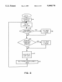
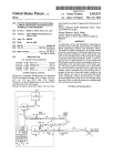
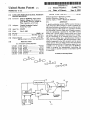
FIG. 2 is a ?ow chart diagram of the main receiver
loop logic of the receiver of FIG. 1;
usefulness due to the short battery life.
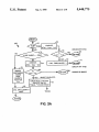
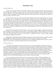
FIG. 3 is a flow chart diagram of the power saving
module Power_Smart_Mode of the loop logic of FIG.
SUMMARY OF THE PRESENT INVENTION
It is therefore an object of the present invention to
provide a battery-powered GPS receiver which can
operate for a long period of time while maintaining a
suf?cient calculation rate.
It is another object of the present invention to pro
2;
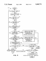
FIG. 4 is a ?ow chart diagram of the shut down
module which conducts several status checks and per
forms acquisitions or reacquisitions before turning off
the power to the RF circuitry of the receiver of FIG. 1;
vide a battery-powered GPS receiver which can con
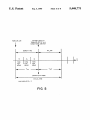
FIG. 5 illustrates the acquisition time cycles imple
tinuously and dynamically respond to various opera
mented to conserve battery power;
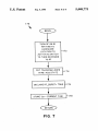
FIG. 6 is a flow chart diagram of the TURN_OF
tional conditions to minimize battery power consump
tion.
It is a further object of the present invention to make
use of the intelligence of an executable program imple
mented on a read only memory (ROM) to control the
power supply to a GPS receiver.
Brie?y, in a preferred embodiment, the present inven
tion comprises a global positioning system (GPS) re
ceiver having radio frequency (RF) circuitry to receive
position signals from a plurality of satellites and provide
F._RF module of the receiver of FIG. 1; and
FIG. 7 is a flow chart diagram of the TUR
N_ON_RF module of the receiver of FIG. 1.
DETAILED DESCRIPTION OF THE
PREFERRED EMBODIMENT
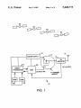
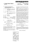
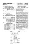
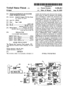
FIG. 1 illustrates a GPS receiver 10 having an an
20 tenna 12, a radio frequency (RF) circuitry 14, a power
an intermediate frequency (IF) signal to a correlator
circuit for generating a pseudo range and a Doppler
measurement for calculating a position ?x. The GPS
receiver further has a power supply system having at 25
least one battery and an alternative external power
connector for connecting to an external DC power
source. The GPS receiver further has a microprocessor
and a read only memory (ROM). The microprocessor is
electrically connected to the RF circuitry and the
power supply system. The ROM includes an executable
supply 16, a power supply controller 18, an application
speci?c integrated circuit (ASIC) 22, a random access
memory (RAM) 23, a microprocessor 24, and a read
only memory (ROM) 26. Antenna 12 receives naviga
tion data signals from a plurality of satellites 32. A list of
visible satellites is kept in the random access memory
(RAM) 23 accessible to microprocessor 24 and ROM
26. Based on the current estimated position of the GPS
receiver 10, the azimuth and the elevation of each satel
lite 32 in the constellation are computed. If the elevation
angle of a satellite is positive and is greater than a mask
program capable of automatically controlling the
angle, e.g., ten degrees, the satellite is considered visi
power supply system to provide a plurality of power
ble. When a satellite ?rst becomes visible, it is ?rst in
cluded in the “to be acquired” list and an acquisition
the RF circuitry so that the battery power consumption 35 operation is executed to obtain the code phase and fre
quency of the satellite signals and collect the satellite’s
is minimized.
ephemeris. The visible satellite is added to the tracking
It is an advantage of the present invention that the
list and maintained as under the “tracking state” when
executable program residing in the ROM can continu
the signals received from the satellite are capable of
ously and dynamically respond to the operation condi
generating measurements. Another situation is that a
tions by adjusting the schedules and power level pro
satellite which has been in the tracking state suddenly is
vided to the RF circuitry to minimize any unnecessary
power consumption.
lost because the signals are blocked by trees, tunnels, or
buildings or because of excessive vehicle dynamics. The
It is another advantage of the present invention that
satellite is categorized as being in the “lost state”. The
with the capability of responding to operational condi
tions, the battery-powered GPS receiver can be used in 45 executable program, residing in ROM 26, constantly
levels ranging from zero to a maximum power level to
inaccessible rural areas and heterogeneous mountain
districts with long battery life without sacri?cing the
frequency of position ?x computations.
It is a further advantage of the present invention that
the collection of almanac and ephemeris data, and the
acquisition and reacquisition of satellites can be carried
out on a substantially regular basis because of the very
checks the states of the satellites 32 and sets a flag for
each satellite indicative of the current tracking state.
After the signals are received from the satellites 32,
RF circuitry 14 ?rst ampli?es and then down converts
the received RF signals to intermediate frequency (IF)
signals. ASIC 22 includes a clock, data ?lters, demodu
lation circuits and integrators to simultaneously process
ef?cient management of battery power during these
through multiple channels the signals received from
operation cycles.
multiple satellites 32. ASIC 22 receives the IF signals
from RF circuitry 14 and generates the pseudo-range
It is a further advantage of the present invention that
a GPS receiver user has the option to input several
operational constants depending on the user speci?c
(code phase) and the Doppler (frequency) measure
ments. These measurements are then used by micro
operations whereby the battery power can be optimally
used for the speci?c operation the user intends to apply.
These and other objects and advantages of the pres
processor 24 for position ?x computations.
ent invention will no doubt become obvious to those of
while capable of performing many intelligent functions
with less power requirements. However, the battery life
of a hand-held portable GPS receiver is still frequently
limited by the power requirements of the RF circuitry
ordinary skill in the art after having read the following
detailed description of the preferred embodiment which
is illustrated in the various drawing ?gures.
BRIEF DESCRIPTION OF THE DRAWINGS
FIG. 1 is a schematic block diagram of a GPS re
ceiver according to the present invention;
With the advance of modern electronics, all elec
tronic components are made smaller in size and mean
65 14. In order to reduce power consumption of the RF
circuitry 14 and to prolong the battery life of GPS
receiver 10, power supply controller 18 is under the
control of an executable program residing in the ROM
5
5,448,773
26 to automatically adjust power level input to RF
circuitry 14 to efficiently utilize the electric power pro
vided by power supply 16.
FIG. 2 is a ?ow chart diagram showing the logic
sequence performed by the executable program residing
in ROM 26 to control power supply 16. The ROM
executable program includes a MAIN_.RC
VR_LOGIC module 40 which is initiated when re
6
are enough good measurements, Ng, to compute a 3-D
position ?x in step 96, or 2) there is calibrated altimeter
available in a step 98 and a 3-D fix is available using
ALTIMETER and GPS in a step 102, or 3) there are no
missed measurements, i.e. Nm=0 in step 94, then a shut
down logic is called in a step 104 to turn the RF power
off and compute a position ?x in a step 106.
Even if there are not suf?cient measurements to com
ceiver 10 is turned on by a step 44. With a step 46, a ?rst
check is made to determine if power supply 16 is con
nected to an external power source. Step 48 determines
if power supply 16 is connected to an external power
pute a 3-D position but if the vertical motion is small
source, and if so, the power saving module POWE
R__SMART_MODE is not executed. If power supply
position ?x is computed in the step 106. If computation
and two-dimensional (2-D) position computation is
achievable as determined in a step 108, again a shut
down logic module is called in the step 104 and a 2-D
of either 3-D or 2-D position is not achievable, then a
16 is not connected to an external power source, an 15 check is ?rst made to determine if VERICAL_MO
operator of the GPS receiver is allowed an option to
bypass the execution of the power saving program. A
check is make to determine if there is an user override
TION is true (step 109). A shutdown logic module is
called if VERICAL_MOTION is not true, otherwise a
sequence of status checks are made to determine
whether another RF burst will be performed (step 116)
command to bypass the execution of the power saving
module in a step 52. The power saving module POWE 20 and the RF power will continue to stay on for one more
RF burst. In step 110, it is ?rst determined if a three-di
R_SMART_MODE is invoked in a step 54 when
mensional ?x is performed during the last RF burst and
power supply 16 is not connected to an external power
source and there is no user override command to bypass
if there are three good measurements and there are at
POWER_SMART._MODE power saving module.
least four visible space vehicles. After satisfying the test
MAIN_RCVR_LOOP 40 is executed on a periodi 25 conditions in step 110, one more RF burst is executed
(step 116), otherwise further tests are performed in step
cal basis such as once per every second to compute and
112 to determine if another RF burst should be exe
update the position ?x and to perform all other general
functions of the receiver. The rate of position ?x com
putations is basically ?xed. A lower rate of position ?x
may be implemented when there is a need to save the
battery power as determined by the logic below. MAI
N_RCVR__LOOP 40 also allocates the visible satellites
to the physical tracking channels and schedules the
measurements to be taken for each satellite on the track
ing list.
cuted, based on the test results from step 112, which
determines whether a two-dimensional ?x is likely to be
successful. Only one more RF burst is allowed because
QUICK__BURST is set to true in step 116 and step 114
checks the value of QUICK-BURST allowing the RF
burst to be executed only once. The purpose of this
logic is to attempt to at least obtain a two-dimensional
35 ?x even if there is vertical motion. The two-dimensional
position ?xes may not be suf?ciently accurate but they
FIG. 3 shows the steps executed by a power saving
can be useful for a GPS receiver to search for the satel
module POWER__SMART_MODE 60 within the
lites.
program of ROM 26. In a step 62, it ?rst determines the
The length of each RF burst depends on the number
on/off status of RF circuitry 14. If the RF circuitry 14
has the power turned off, the time that the power is off 40 of channels, the number of satellites and the length of
time required for each satellite. For example, if GPS
is ?rst computed in a step 64 and the time off is com
receiver 10 is a three-channel receiver and the time
pared to the length of time that the power is scheduled
required for each satellite is 0.5 second, for a group of
to be off, i.e., Toff in a step 66. If the time off is still
seven satellites an RF burst of 1.5 seconds,i.e. three
within the time window of scheduled time off, the exe
cution of POWER__SMART_MODE 60 is ?nished for 45 times 0.5 seconds, is required, where three is the number
of RF cycles needed to handle seven satellites with
this pass and returned to the beginning of MAIN_RC
three channels. The length of the RF burst is thus de
VR_LOOP 40. Otherwise a subroutine TUR
signed to be suf?cient to obtain a measurement from
N_ON_.RF is called in a step 72 before returning in a
each satellite on the tracking list.
step 74. On the other hand, if the RF power is on, in a
FIG. 4 shows the logic of a SHUT_DOWN Module
step 76 an enquiry is made to determine if time is within
120 of the program of the ROM 26. When SHUT
the window of an RF burst, i.e., RF_BURST=true,
DOWN module 120 is called, it ?rst sets QUICK_CY
and if POWER__SMART_MODE is true. A normal
CLE to a value of false (step 121) and checks whether
continuous power mode with position ?x computation
the GPS receiver 10 knows the time in a step 122. If so,
is executed in a step 78 proceeded with calling a shut
down logic module in a step 82. If RF burst=true and 55 it checks if there is a position ?x in a step 124, and if yes,
POWER_SMART_MODE=true as determined in
step 76, the time of the RF power on is calculated in a
'step 84 and compared with the scheduled RF power on
time window, i.e., Ton in a step 86. It loops back to
continue the wait if the calculated time on is within the
time window in a step 88, otherwise the RF burst is
if it is time to collect more almanac or ephemerals data
in a step 126. The RF power is kept on if either of the
test results for the ?rst two enquiries, i.e. steps 122 or
124, are negative or the test result of the third enquiry,
i.e. step 126, is positive. The age of the GPS almanac is
checked periodically so that it is generally no more than
twelve hours old. A ?ag is set if a new almanac is
needed or if no almanac is available. Before the RF
A test is made to determine how many good measure
power is turned off, it is further tested if any visible
ments, i.e., Ng, and how many missed measurements
,i.e. Nm, are processed by use of the signals received 65 space vehicles (SVS) which have not been acquired -in a
step 128, or if any SVS have been lost and whether a
from the satellites in a step 92. When there are suf?cient
three-dimensional ?x having a PDOP less than six (step
good measurements to compute a three-dimensional
completed.
(3-D) position ?x, including the conditions that 1) there
132) is not available with the current tracking list. If
7
5,448,773
8
not disrupted when a satellite is lost or not yet acquired.
either of the above tests, i.e. steps 128 or 132, are true,
a satellite acquisition cycle begins in a step 134 or 136
and a flag TRYING_TO__ACQ is set to l, i.e. true,
otherwise it is set to zero, i.e. false in a step 138. The
purpose of step 132 is to save power when there are lost
satellites but a good ?x is available anyway. TURN__R
F_OFF is then called to save power without trying to
The acquisition is accomplished with the RF power
turned on only periodically. Meanwhile a test is made to
determine if a 2-D solution is sufficient. No second
attempt will be made if there is enough data for a 2-D
position ?x. The RF power is turned off right after the
RF burst.
FIG. 6 illustrates the logic of TURN_OFF_RF
acquire the lost satellite. Otherwise,the acquisition is
attempted for a maximum number of times, i.e.
module 150 of the ROM 26. It ?rst calculates the on
ON_CNT_MAX in step 142 and for a maximum num
time, i.e. Ton and off time Toff by ?rst determining the
ber of cycles, i.e. CYCLE_MAX in step 144 then the
maximum number of space vehicles (SVS) on each of
the GPS receiver channels in a step 152 and Ton is the
product of maximum number of SVS and the time per
measurement which is ?xed constant in a step 154. Toff
cycle is reset to zero in a step 146 and the RF power is
turned off in a step 148.
In order to acquire a new satellite, a large range of
frequency and code phases must be searched to ?nd the 15 is computed by subtracting the on time from the cycle
satellite signals, thus it takes a longer duration to ac
time in a step 156. The RCVR tracking loops are put in
quire new satellites with RF burst. Therefore, initial
an idle state in a step 158 and a hardware command is
acquisition will require the RF circuitry 14 to be on for
issued to activate a switch to shut off power to RF in a
a period of time which is adequate to complete the
step 162 to save power. The state of RF power is set to '
search and the search must also be made consecutively
off in a step 164 and the time when RF power is turned
in time. It is normal that new satellites added to the
tracking list will not be acquired, for as long as a few
off is set to the current time in a step 166. The RF power
will be turned on when a preset scheduled time off is up
minutes, when the elevation mask is low because of
blocking by trees or buildings. In order to conserve
(see steps 66 and 72).
battery power, the acquisition is only attempted periodi
Instead of setting the CYCLE_TIME as a constant,
25
cally with the RF on for an adequate time to properly
search for the satellite. The power provided to RF
circuitry 14 is turned on continuously for a period of
ACQ_ON_TIME and then turned off until next RF
ACQ..._CYCLE_.TIME is due (FIG. 5). A power sav
ing is achieved because the RF power is not kept on
TURN__OFF_RF logic 150 adaptively changes the
through the entire acquisition time. A similar technique
CYCLE_TIME as a function of speed. This adaptive
process is enabled by a user’s setting ADAPTIVE:
TRUE. This is particularly useful when a GPS receiver
is moving at a high speed. It is to be noted that if a
receiver is moving at a constant velocity vector there is
no dead reckoning (DR) error if even the receiver is
moving at high speed. However, if a turn is made at
is used to acquire lost satellites. Reacquisition is treated
slightly different because there is typically more infor
high speed, a large DR error is generated. By making
the CYCLE_TIME a function of speed, the magnitude
mation available about a lost satellite and it can be found
in shorter length of time. The on and off times are set
of the DR error can be reduced. It is ?rst tested to
determine if a user optional input, i.e., ADAPTIVE, is
set to be TRUE (step 156-1). If ADAPTIVE is TRUE
and the the speed of the GPS receiver is greater than a
threshold speed S2, as determined by step 156-1, then
differently. An example of time limits for reacquisition
is to maintain the power on for a time period of ten
seconds and a cycle time of thirty seconds, while for
initial acquisition the power is kept on for thirty seconds
the power to RF is kept on continuously and the execu
instead of ten and a cycle time of one hundred and
twenty seconds instead of thirty.
The acquisition and reacquisition operations are im
plemented in the SHUT_DOWN logic. Before the RF
circuitry 14 is turned off, attempts are made to acquire
45
and reacquire the new or lost satellite. The acquisition
or reacquisition are repeated 21 ?xed number of cycles
before proceeding to shutoff of the RF power. Since the
SHUT_DOWN logic is called repeatedly after a ?xed
time interval, acquisition and reacquisition will be at
tempted again if the previous operation fails. Since for a
hand-held GPS receiver 10, the most frequent situation
tion of TURN_OFF_RF logic 150 is terminated and
returned to the calling module (step 156-3). The RF
power is kept on until the speed is reduced below S2 or
when the user turns off the adaptive process by setting
ADAPTIVE to FALSE. If the speed of the receiver is
less than S2 as determined by step 156-1, then the speed
is compared to a ?rst threshold speed, i.e. S1 in step
1564. If the speed is greater or equal to S1, then a new
cycle time which is half of the regular cycle time is used
(step 156-5), otherwise a regular CYCLE_TIME is
kept unchanged and the program proceeded with step
156.
is the temporary loss of communication due to tree or
FIG. 7 shows the logic operations of TUR
building blockage, power saving is achieved by not
N_ON_RF module 170 of the ROM 26. A hardware
keeping the RF power for the entire period of time 55 command is ?rst issued to activate the switch to turn on
when trying to reacquire the lost satellite.
the RF power in a step 172. The RF tracking loop is set
When a SHUT._.DOWN is performed, the power
' provided to RF circuitry 14 is turned off for a brief
period of time which depends on the desired accuracy
of the dead reckoning while the RF is off, the number of
channels of the receiver, the distribution of the satellites
to each channel, and the way that satellites are acquired.
For a hand-held GPS receiver 10, because the accelera
tion is generally low and the accuracy requirement is
typically at about 100 meters, a turn off time of four to 65
five seconds is generally acceptable.
An important factor for power savings as taught in
this invention is that the bene?ts of power savings are
to a reacquisition state, i.e. RE_ACQ= 1, in a step 174-.
The RF burst is set to l (TRUE) to begin the RF burst
cycle in a step 176 and the starting RF on time, i.e. t-on,
is set to the current time in a step 178. The executable
program residing in ROM 26 further computes a veloc
ity vector of the GPS receiver 10 to determine the
number of satellites and therefore position signals
needed to compute a position ?x, e.g., the number
needed to satisfy a position accuracy requirement. A
determination is made of the number of satellites that
are providing position signals. The executable program
turns-off power to the RF circuitry for a predetermined
5,448,773
10
3. The GPS receiver of claim 2 wherein:
said executable program in said memory further in
duration of time when the actual number of satellites
equals or exceeds the required number of satellites, in
cludes means for a GPS user to input at least one
order to conserve battery power.
threshold speed; and
The executable program residing in ROM 26 prefera
said executable program further includes means to
bly includes a routine for determining if the actual num
ber of satellites visible is less than the number of satel
determine if speed of the GPS receiver is greater
than said threshold speed, and adjusting said time
lites required for position signals, e.g., a two dimen
sional position ?x may be suf?cient and available.
gap duration between said RF circuitry power-on
periods as a function of said velocity vector of the
GPS receiver when the speed of the GPS receiver
The executable program residing in ROM 26 stores a
plurality of historical position ?x data and a list of the
visible satellites. If the actual number of satellites that
position signals are being received from is less than a
is greater than said threshold speed.
4. The GPS receiver of claim 1, wherein:
said executable program in said memory further in
cludes means for storing a plurality of historical
position ?x data and a list of visible satellites, and if
said actual number of satellites wherefrom said
position signals are being received is less than said
required number, the history of position ?x data and the
list of the visible satellites is used to determine if an
additional RF burst should be performed to add the
available measurement data.
Although the present invention has been described in
terms of the presently preferred embodiment, it is to be
understood that such disclosure is not to be interpreted
as limiting. Various alternations and modi?cations will
required satellites wherefrom said position signals
must be received, said executable program further
includes means by using said historical position ?x
data and said list of visible satellites to determine if
an additional RF circuitry power-on is to be per
after reading the above disclosure. Accordingly, it is
formed.
intended that the appended claims be interpreted as
5. The GPS receiver in accordance with claim 1,
covering all alternations and modi?cations as fall within
25 wherein:
the true spirit and scope of the invention.
said executable program in said memory further in~
I claim:
cludes means for determining if one of said satel
1. A global positioning system (GPS) receiver having
lites is lost and if said lost satellite has a low eleva
a radio frequency (RF) circuitry to receive position
tion and to discontinue a satellite acquisition for
signals from a plurality of satellites and to provide an
said lost satellite with said low elevation.
intermediate frequency (IF) signal to a correlator cir 30
6. A GPS receiver in accordance with claim 1
cuitry for generating a pseudo range and a Doppler
wherein:
measurement for calculating a position ?x, the GPS
said executable program in said memory further in
receiver further comprising:
cludes means for determining if said actual number
a power supply system having at least one battery and
no doubt become apparent to those skilled in the art
an alternative external power connector for con
necting to an external power source; and
a microprocessor having a read only memory, the
of satellites is less than said required number of
satellites wherefrom said position signals must be
received; said executable program further includes
microprocessor being electrically connected to
means for determining if a two dimensional posi
tion ?x is suf?cient and available, and to turn off
the RF power when said actual number of satellites
said RF circuitry and the power supply system; and
an executable program stored in said memory for
is less than said required number of satellites during
a period of time, wherein the battery power is
automatically controlling the power supply system
to provide on/off power control to said RF cir
cuitry, and having means for computing a velocity
conserved.
vector of the GPS receiver for determining a re
quired number of satellites wherefrom said position
signals must be received for computing said posi
45
7. A battery-operated global positioning system
(GPS) receiver with extended battery life operation,
comprising:
tion ?x to satisfy a position accuracy requirement,
a battery connected to power said GPS receiver;
said executable program further includes means for
a receiver section for receiving position signals from
determining from monitoring said position signals
a plurality of orbiting GPS satellites;
are being received, said executable program con
power switch means connected between the receiver
section and the battery for turning power on and
off to the receiver section in response to a control
trols the power supply system to cut off battery
power to said RF circuitry for a predetermined
navigation computer means connected to the receiver
received from said plurality of satellites an actual 50
number of satellites wherefrom said position signals
signal; and
duration of time when said actual number of satel 55
lites is greater or equal to said required number of
satellites wherefrom said position signals must be
received, wherein a saving of battery power is
provided whenever the power supply system is not
signal when the navigation computer means re
quires updates of said position signals to provide a
position ?x for said GPS receiver, wherein the
battery life of the battery is extended by periodi
cally powering-off the receiver section, and in
provided with said external source of power at said
alternative external power connector.
2. The GPS receiver of claim 1, wherein:
said executable program in said memory further in
cludes means for determining a time gap duration
between successive RF circuitry power-on periods
as a function of said velocity vector of the GPS
receiver wherein a dead reckoning (DR) error is
reduced.
section for tracking said plurality of orbiting satel
lites and to the power switch means for turning on
power to the receiver section with said control
cludes means for computing a velocity vector of
said GPS receiver that in?uences the minimum
65
number of GPS satellites providing said position
signals that must be received for computing said
position ?x to a predetermined position accuracy,
and further includes means for extending and short
5,448,773
11
'
12
ening the time that said control signal causes the
receiver section to be powered-on or powered-off
in response to the time necessary to receive said
power switch means connected between the receiver
Section and the battery for turning power on and
off to the receiver section in response to a control
position signals from said‘ minimum number GPS
satellites_
Signal;
5
navigation computer means connected to the receiver
8_ The GPS receiver of Claim 1, further comprising:
section for tracking said plurality of orbiting satel
man-machine interface means for user input of a num
lites and to the power switch means for turning on
power for a period of time to the receiver section
ber representing a threshold velocity;
comparator means coupled to the man-machine inter
face means and navigation computer means for 10
determining if said computed velocity vector ex
ceeds said threshold velocity; and
power-on frequency adjusting means connected to
puter means requires updates of said position sig
nals to provide a position ?x for said GPS receiver,
wherein the battery life of the battery is extended
by periodically powering-off the receiver section;
the comparator means and the power switch means 15
for increasing the on-time of the receiver section
whenever said computed velocity vector exceeds
said threshold velocity, otherwise the on-time of
the Tecelver sectlon 15 not affe°ted_~_
with said control signal when the navigation com
constellation means connected to the navigation com
puter means for determining if the number of GPS
satellites accessed by the receiver section exceeds a
required predetermined number of GPS satellites;
and
_
shut-down means connected to the power switch
9- A balitery'oPel'ated global posltlfmmg syslem 20
(GPS). {ecclvef Wlth Extended battery llfe opel'atlon,
means and constellation means for turning-off
power to the receiver section whenever there are
compnsmgz
a battery connected to power sald GPS recelver;
lost satellites, but a sufficient number of GPS satel
lites have been accessed after a period of time to
a receiver section forereceiving position signals from
a plurality of orbiting GPS satellites;
make available a good position ?x.
25
3O
35
40
45
5O
55
60
65
*
*
*
*
*