1
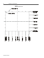
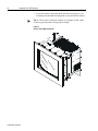
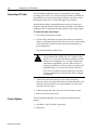
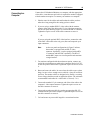
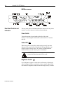
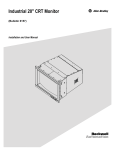
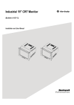
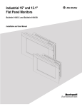
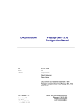
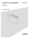
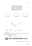
Industrial 21" CRT Monitor
(Bulletin 6158)
Installation and User Manual
2
Table of Contents
7DEOH RRII &RQWH
&RQWHQQWV
Industrial 21" CRT Monitor..............................................
Description...........................................................................
Package Contents .................................................................
Dimensions ..........................................................................
Installing the 6158 Industrial Monitor...................................
Connecting AC Power ..........................................................
Product Options....................................................................
Connecting to a Computer ....................................................
Rear Panel Controls and Indicators .......................................
Maintenance.........................................................................
Allen-Bradley Support .........................................................
Troubleshooting ...................................................................
Specifications ......................................................................
Important User Information
3
3
4
5
7
10
10
15
16
18
19
20
21
Solid state equipment has operational characteristics differing from those of
electromechanical equipment. "Safety Guidelines for the Application, Installation, and
Maintenance of Solid State Controls" (Publication SGI-1.1) describes some important
differences between solid state equipment and hard-wired electromechanical devices.
Because of this difference, and because of the wide variety of uses for solid state
equipment, all persons responsible for applying this equipment must satisfy themselves
that each intended application of this equipment is acceptable.
In no event will Rockwell Automation be responsible or liable for indirect or
consequential damages resulting from the use or application of this equipment.
The examples and diagrams in this manual are included solely for illustrative purposes.
Because of the many variables and requirements associated with any particular
installation, Rockwell Automation cannot assume responsibility or liability for actual
use based on the examples and diagrams.
No patent liability is assumed by Rockwell Automation with respect to use of the
information, circuits, equipment, or software described in this manual.
Reproduction of the contents of this manual, in whole or in part, without written
permission of Rockwell Automation is prohibited.
Throughout this manual, we use notes to make you aware of safety considerations.
ATTENTION: Identifies information about practices or
circumstances that can lead to personal injury or death,
property damage, or economic loss.
Important: Identifies information that is especially important for successful
application and understanding of the product.
Publication 6158-5.0
Industrial 21" CRT Monitor
3
,QGXVWULDO &57 0RQLW
0RQLWR
RU
Description
The Bulletin 6158 21" Industrial CRT Monitor is a general purpose
monitor suitable for a wide range of industrial computing applications.
ATTENTION: The equipment described in this
document generates, uses, and emits radio frequency
energy. The equipment has been tested and found to
comply with FCC Rules, Part 15, subpart J, for Class A
computing devices.
The use of non-shielded interface or power cords with
Allen-Bradley industrial monitors is prohibited.
ATTENTION: X-ray emissions from these monitors are
typically about 0.05 mR/hr maximum, well below the 0.5
mR/hr maximum recommended by the US. Department of
Health and Human Resources and specified in "Federal
Performance Standards for Television Receivers", Section
10, Part 1020, Title 21, of the U. S. Code of Regulation
(PL90-620), Vol. 38, No. 198.
These monitors are equipped with X-ray protection
circuits which cause automatic shutdown of the
equipment in case its X-ray emissions begin to approach
Federal limits.
Publication 6158-5.0
4
Industrial 21" CRT Monitor
Package Contents
The monitor shipping carton contains the following items:
• Monitor
• Package of mounting hardware
• AC power cord (optional)
• Video cable (optional)
• This user manual
A 6158 Industrial Monitor with a touchscreen option is shipped with
these additional items:
• Supporting software and manuals
• RS-232 serial extension cable (optional)
Unpacking the Unit
Before unpacking a new monitor, inspect the shipping carton for
damage. If damage is visible, immediately contact the shipper and
request assistance. Otherwise, proceed with unpacking.
Note:
Publication 6158-5.0
Make sure you keep the original packaging for the monitor
in case you need to return the monitor for repair.
Industrial 21" CRT Monitor
Dimensions
5
Figure 1
6158 Industrial Monitor - Physical Dimensions
Publication 6158-5.0
6
Industrial 21" CRT Monitor
Figure 2
Panel Cutout Dimensions
Publication 6158-5.0
Industrial 21" CRT Monitor
Installing the 6158
Industrial Monitor
7
Environmental Considerations
The 6158 Industrial Monitor requires a minimum free air space of 76.2
mm (3 in.) behind and 50.8 mm (2 in.) above and below for proper
cooling. Allen-Bradley Industrial Monitors have been designed to
function without cooling fans. Therefore, maintenance of fan filters and
access to them need not be a concern.
Strong magnetic fields near the front of the monitor outside the enclosure
could potentially distort the image over time. This type of image
distortion generally disappears after degaussing occurs. Allen-Bradley
industrial monitors automatically degauss each time AC power is
applied, or when the degauss button is pressed.
Note:
The internal degauss will not prevent color impurities
caused by local magnetic fields. Make certain the monitor’s
enclosure is free of residual magnetism.
Installation Instructions
The 6158 Industrial Monitor has a 9U panel height and is designed to
meet NEMA 4 and NEMA 12 standards when properly installed.
The panel on which you mount the monitor should be at least 14 gauge
to insure a NEMA 4 seal and proper support for the unit. The mounting
studs attached to the rear of the monitor bezel will accommodate this
minimum thickness panel and panels up to 6.35 mm (0.25 in.) thick.
The monitor may also be bolted to the front rails of EIA standard 19 in.
rack cabinets.
To install the 6158 Industrial Monitor:
1. Confirm that the shipping carton contains a package of 20 10–32
lock nuts and 20 flat washers. You will need 18 nuts and washers for
installation.
2. Refer to the physical dimension drawings (Figure 1) and confirm
that there is adequate space behind the panel. Remember to allow
extra space for air circulation.
3. Refer to the panel cutout drawing (Figure 2) for dimensions of the
panel cutout and mounting hole locations. Cut and drill the panel.
4. Carefully remove the monitor from its packaging. Avoid damaging
the monitor gasket.
Publication 6158-5.0
8
Industrial 21" CRT Monitor
5. Insert the monitor in the panel cutout from the front (Figure 2). Do
not damage the threaded mounting studs as you position the monitor.
Tip: It will be easier to install the monitor if you support it with a shelf
or other support adjusted to the appropriate height.
Figure 3
Generic Panel Mount Diagram
Publication 6158-5.0
Industrial 21" CRT Monitor
9
6. Secure the unit with the locknuts and washers provided. Tighten
evenly to 24 inch–pounds of torque.
Important: To assure a proper seal, be sure to install a washer and nut
on each of the 18 mounting studs.
ATTENTION: Mounting nuts must be tightened to a
torque of 24 inch–pounds to provide panel seal and avoid
potential damage. Rockwell Automation assumes no
responsibility for water or chemical damage to the
monitor or other equipment within the enclosure due to
improper installation.
7. Remove the protective adhesive sheet from the screen of the
industrial monitor. The sheet is designed to prevent scratching of the
polycarbonate screen protector or the optional touchscreen during
shipping and installation. It should be removed before use.
Publication 6158-5.0
10
Industrial 21" CRT Monitor
Connecting AC Power
The 6158 Industrial Monitor requires a single phase power supply
providing 100 to 250V AC at 50 to 60 Hz. Power must be available at a
grounded three–pin outlet located nearby. Whenever possible, connect
the monitor to the same AC source that supplies the computer.
Allen-Bradley monitors automatically adjust to the line voltage and
frequency supplied to them (within the limits specified). No switches or
jumpers need to be changed to match the monitor to the voltage supply.
To connect AC power to the monitor:
1. Turn off the main switch or breaker.
2. Use the GND point on the rear panel of the monitor to establish a
chassis to earth ground connection. Secure one end of a ground strap
to the GND point. Connect the other end of the ground strap to a
good earth ground.
The ground terminals are M5 screws.
ATTENTION: Chassis ground must be connected for
safe operation of the monitor. The AC receptacle on the
monitor is a 3–wire type with chassis ground pin, and the
mating AC cord supplied is a 3–wire type, designed for
connection to a grounded 3–pin AC outlet. However a
properly grounded AC outlet is not always available, and
grounding using a 3–wire cord can easily be defeated.
If you fail to ground the monitor properly, the setup may
result in personal injury from electrical shock or damage
to equipment.
3. Connect the socket end of the AC power cord to the mating
connector on the rear panel of the monitor. Position the power cord
retaining clip attached to the rear panel connector over the cord’s
socket to secure it in place.
4. Connect the plug end of the AC power cord to the mains outlet.
5. Restore AC power to the outlet.
Product Options
The 6158 Industrial Monitor can be configured with the following
options.
• VGA HD-15 or RS-343 BNC video cables
• touchscreen
Publication 6158-5.0
Industrial 21" CRT Monitor
11
Video Cables
The monitor can be configured with various industrial grade video
cables. The standard HD-15 cable is equipped with a conventional HD15 connector at each end.
Figure 4
HD-15 Video Cable Connector
Table A
HD-15 Connector Pin Assignments
Pin
1
2
3
4
5
6
7
8
9
10
11
12
13
14
15
Signal
Red Video
Green Video
Blue Video
ID2
Composite Sync
Red Video Return
Green Video Return
Blue Video Return
Reserved
Ground
ID0
ID1
Horizontal Sync
Vertical Sync
Reserved
Description
Input, analog
1
Input, analog
Input, analog
Output, TTL low
Input, TTL, pulsed
Output, TTL low
Output, TTL floating
2
Input, TTL, pulsed
Input, TTL, pulsed
1
Monochrome video generators should present video to this pin. Composite
sync may be presented to this pin together with green or monochrome video. In
this case, the monitor’s sync selector switch must be set to “Sync on Green.”
2
With a VGA adapter, the polarization of this signal, together with the
polarization of the vertical sync signal, vary with the adapter’s operating mode,
as shown in the table below. This mode information is not needed by the
monitor, since it is a variable scan monitor.
Signal
H Sync
V Sync
Mode 1
+
-
Mode 2
+
Mode 3
-
Mode 4
+
+
Publication 6158-5.0
12
Industrial 21" CRT Monitor
Another low noise video interface is the Differential BNC Input
connectors option which accepts red, green and blue video signals (RS–
343 analog signaling) and a separate composite sync signal from the
video source. BNC to BNC cable options are available.
Touchscreen Option
The touchscreen option (6158-xxAxxxxxx) provides an anti-glare
touchscreen system. A software driver provided with the touchscreen
option allows you to use the touchscreen as a pointing device with many
popular DOS and Windows–based industrial applications. Refer to the
touchscreen documentation for information on installing and using the
touchscreen.
Touchscreen Serial Cable
For units configured with the touchscreen option, a touchscreen serial
cable is required. A suitable cable can be obtained from your Rockwell
Automation sales representative.
The cable provides a communication channel between the touchscreen
controller, which is mounted inside the monitor, and an RS-232-C serial
port on the host computer. The touch controller is provided with power
from the monitor’s power supply. Accordingly, no external touch power
connections are necessary.
The touch controller is set up to detect the baud rate used by the host. For
additional information on controller configurations, please refer to the
documentation provided with the touch system.
Publication 6158-5.0
Industrial 21" CRT Monitor
13
Cable Connectors
The following diagram and table indicate the pin configuration of the
DB9 cable connector and the signals assigned to those pins.
1
2
6
3
7
4
8
VIEW LOOKING INTO
PIN END OF MALE CONNECTOR
OR
SOLDER TERM END OF FEMALE CONNECTOR
5
9
DB9
Monitor
Signal
Connect to Host
DB-9
DB-25
1
FG
2
TX Data (output)
1
8
RX Data (input)
2
3
3
Not Connected
4
DSR (input)
3
2
DTR (output)
4
20
5
SG
SG
5
7
6
DTR (output)
DSR (input)
6
6
7
CTS (input)
RTS (output)
7
4
8
RTS (output)
CTS (input)
8
5
9
x level
RI
Touchscreen Software
Prior to using the touchscreen, you must install the touchscreen driver
software on the host computer and perform a calibration procedure.
Details for installation are covered in the documentation that is provided
with the touchscreen system.
Everything you need to install the touchscreen driver software is
included in the touchscreen software packet provided with the system. It
contains a utility program that makes installation very easy. Before
attempting to install the touchscreen software, ensure that the version of
the operating system running on the target machine is compatible with
that required by your particular touchscreen system. There are a few
things the user must know about the touchscreen hardware configuration
of the touch system in order to install the driver properly.
• The type and model of touch controller being used.
• The COM port in use for the touchscreen. Ensure that the RS-232
cable is properly installed between the monitor port and the host’s
COM1 or COM2 port. Note the COM port being used.
• The touchscreen controller detects the baud rate of the host’s COM
port and automatically adjusts to that rate.
The installation procedure involves transferring driver files from the
diskette supplied with the touch system to the host computer’s hard disk,
and adding instructions to system startup files that will load the drivers
following system boot-up. The installation utility automates the transfer
Publication 6158-5.0
14
Industrial 21" CRT Monitor
process and creates a special directory on the hard disk to hold the touch
software. The user may specify a directory path name; otherwise, a
default path name is used. In addition, the utility modifies the system
startup files appropriately.
Touchscreen Calibration
After installing the driver software, follow the instructions in the
manufacturer’s documentation provided with the touch system.
ATTENTION: The calibration of the touchscreen will be
invalidated by any subsequent adjustment of the display
size or position. Insure that the display is properly
adjusted before beginning calibration.
When the touch system is to be used with multiple
applications, and these applications use different video
display modes, the calibration procedure should be
repeated for each mode that is to be used.
Using the Touchscreen with Application Programs
Following the installation of the touch software and calibration, the
touchscreen is ready to use.
Since, in general, the touchscreen emulates a mouse, compatibility issues
can arise in relation to the way the touchscreen emulates mouse buttons,
especially multiple buttons. For a complete discussion of these issues,
and means of resolving problems, see the relevant sections of the
manufacturer’s documentation.
Polycarbonate Window Option
A polycarbonate window option (6158-xxYxxxxxx) is available for
applications that require an added measure of protection for the monitor
screen.
Publication 6158-5.0
Industrial 21" CRT Monitor
Connecting to a
Computer
15
Connect the 6158 Industrial Monitor to a computer with the appropriate
video cable. A touchscreen serial cable is required for monitors equipped
with the touchscreen option. To connect your monitor to a computer:
1. Plan the route for the cables and confirm that the cables you have
ordered are long enough for the routing you have chosen.
2. If you are using a standard HD-15 video cable with the monitor,
connect either end of the cable to the 15–pin video input connector.
See the rear panel drawing (Figure 5) to locate the HD-15 connector.
Tighten the captive screws on the cable connector to secure it.
Or
If you are using the optional BNC video interface, connect the ends
of the BNC video cable to the red, green, blue and composite sync
input connectors.
Note:
As the rear panel configurations in Figure 5 indicate,
the monitor is equipped with an HD-15 video
connector. Optionally, it can be equipped with an HD15 connector and four BNC connectors. The HD-15
and the BNC inputs are wired in parallel and constitute
a single interface.
3. For monitors configured with the touchscreen option, connect one
end of the serial touchscreen cable to the connector labeled “AUX1”
on the rear panel of the monitor. Tighten the captive screws to secure
it.
4. Route and secure the cables. In cases where the cable crosses a door
hinge, be sure to leave enough excess cable for a loose fit in all door
positions. The monitor cables are designed to be flexible, so routing
across a hinge should not result in application failure. The minimum
recommended bend radius for a video cable is 38 mm (1.5 in.).
5. Connect the standard 15–pin connector end of the video cable to the
computer’s video output connector. Tighten the captive screws on
the cable connector to secure it.
6. Connect the touchscreen cable free end to an appropriate RS–232
communications port on the computer. Tighten the captive screws on
the cable connector to secure it.
7. Coil and secure any extra cable length in a convenient location.
Publication 6158-5.0
16
Industrial 21" CRT Monitor
Figure 5
Rear Panels of Monitor
Rear Panel Controls and
Indicators
The rear panel of the 6158 Industrial Monitor contains all of the picture
controls, as well as the power switch and status indicator.
Power Switch
Turn on the monitor by pressing the right side of the switch
marked “I”. (Pressing the left side of the switch marked “0” turns the
unit off).
Status LED (
)
When the monitor is powered up and operating correctly, the status
indicator LED (green) will be illuminated. If the light should go out
while the power switch is in the ”on” position, a misadjustment or
malfunction has occurred. Remove power immediately.
ATTENTION: Do not assume that the monitor is
powered off when the status LED is not lit.
Brightness Control ( )
Use the brightness control to adjust the overall intensity of the display.
After allowing the CRT to warm up for at least a minute, adjust for the
least amount of brightness needed to make the display clearly viewable.
Publication 6158-5.0
Industrial 21" CRT Monitor
17
Contrast Control ( )
Use the contrast control to vary the difference between the display’s light
and dark elements. With a suitable image displayed on the screen, adjust
the contrast control to achieve the best balance between image brightness
and fine detail rendition. The optimum setting may vary slightly with
different types of displays and changes in ambient lighting, as well as
individual taste.
Manual Degaussing Button (
)
The display screen is degaussed automatically each time the monitor is
powered on. This degaussing eliminates color impurities and other
distortions of the display by neutralizing the effects of magnetic fields in
the surrounding environment.
When the unit is left on for a long period, or is repositioned following
power-up, the screen may pick up additional magnetic flux, causing
colors to appear ”blotchy” or otherwise distorted. If this happens,
degauss the screen manually by pressing the degaussing button. For full
effectiveness, allow at least fifteen minutes between manual degaussings.
Shorter intervals may result in an incomplete removal of flux and
residual color impurities. If the unit is located near electric transformers,
motors, loudspeakers or other strong magnetic sources, degaussing alone
may not be sufficient to eliminate interference. Try reorienting the unit
relative to the magnetic source or moving the monitor further away.
Vertical Size (
)
Use this control to make the display taller or shorter. Consult the chart
following for recommended display height.
Vertical Position (
)
Use this control to center the display vertically on the screen.
Horizontal Size (
)
Use this control to make the display wider or narrower. Consult the chart
below for recommended display width.
Horizontal Position (
)
Use this control to center the display horizontally on the screen.
Publication 6158-5.0
18
Industrial 21" CRT Monitor
Maintenance
Preparation for Shipment
If it is ever necessary to ship the monitor, first remove it from the panel
in which it has been installed, then securely pack it. To remove the
monitor from the panel, reverse the installation procedure that begins on
page 7. Whenever possible, ship the monitor in its original container.
ATTENTION: Never try to ship the monitor while it is
mounted in a panel. Doing so could result in damage to
the panel or monitor.
Cleaning instructions
Occasionally clean the monitor panel and cabinet with a soft cloth
dampened (not soaked) with a mild household detergent (non-abrasive).
Ensure that air vents are cleared of dust.
The screen may be cleaned with a soft cloth dampened with a mild glass
cleaner. Keep turning a fresh side of the cloth toward the screen surface
to avoid scratching it with accumulated grit. To minimize the risk of
abrasion, allow the screen to stand dry.
Special care should be taken when cleaning a resistive touchscreen or
polycarbonate shield that is installed over the CRT screen. The surface
can be easily damaged by abrasive and certain chemical cleaners. Never
use alcoholic or ammoniac cleaners.
Replace air filters over fans or heat exchanger intakes periodically to
ensure proper air flow for cooling. (Applicable to units in some industrial
enclosures.)
Publication 6158-5.0
Industrial 21" CRT Monitor
Allen-Bradley Support
19
Allen-Bradley offers support services worldwide with over 75
sales/support offices, 512 authorized distributors, and 260 authorized
system integrators located throughout the United States alone, plus
Allen-Bradley representatives in every major country in the world.
Local Product Support
Contact your local Allen-Bradley representative for:
• sales and order support
• product technical training
• warranty support
• support service agreements
Technical Product Assistance
If you need to contact Allen-Bradley for technical assistance, please
review the information in the Troubleshooting section first. Then call
your local Allen-Bradley representative.
Publication 6158-5.0
20
Industrial 21" CRT Monitor
Troubleshooting
Symptom
Status LED does not come on when
power switch is closed.
The following table can help you identify the potential cause of problems
you may encounter while using the 6158 Industrial Monitor.
Possible Problem
Action
Power cord not connected.
Open power switch. Reconnect power cord at
monitor and at AC outlet. Close power switch.
No power available at AC outlet.
Test AC outlet by plugging in a lamp or other
known good device.
Power cord faulty.
Replace power cord.
Monitor faulty.
Have monitor serviced.
Screen saver activated
Disable screen saver by activating an input to
the host system.
Brightness and contrast controls not
properly adjusted
Turn brightness and contrast controls CW.
No raster visible even when brightness
and contrast controls are set full CW.
Monitor out of adjustment or faulty
Have monitor serviced.
Raster dimly visible with brightness and
contrast controls set full CW, but no
display present
Video cable problem
Check for proper installation of video
cable(s). Refer to installation instructions.
Status LED is on, but screen is blank.
Display is present, but garbled or rolling.
Replace suspected faulty cable(s).
Fault in video source
Test video source by connecting to another
monitor that is known to be operational.
Fault in monitor
Have monitor serviced.
Monitor not synched to video source.
Refer to installation instructions.
Check for proper video cable installation.
Replace suspected faulty cable.
Check to ensure that video source is
operating within the monitor’s range.
Display is present and stable, but appears
“wrapped” at one side or otherwise not
properly centered or sized.
Size and position controls misadjusted.
Adjust controls for proper size and position of
display. Refer to operator instructions.
Display is present and stable, but missing
some color(s)
Video cable problem
Check for proper video cable installation.
If using BNC inputs, test monitor as follows.
Disconnect signal cable(s) corresponding to
the missing color(s). Disconnect signal cable
corresponding to a displayed color and
connect it to the input(s) corresponding to the
missing color(s). If a missing color reappears,
the signal cable corresponding to that color is
faulty; otherwise, the monitor is faulty.
Replace suspected faulty cable.
Fault in monitor.
Have monitor serviced.
Display is present and stable, but colors
are not pure
Monitor requires degaussing
Manually degauss the monitor. Refer to
operator instructions.
Display is present, but “jitters” or is
severely distorted
Interfering external AC or DC magnetic
shield
If possible, reposition the monitor beyond the
proximity of large transformers, motors, bus
bars, etc.
“Noise” generated by other equipment
in the environment is present at the
video inputs
Consult the application note which discusses
method’s of eliminating noise using the
monitor’s differential inputs.
NOTE: Do not confuse the flicker
associated with an interlaced video mode
with jitter.
Display is present, but “bars” appear
across it.
Publication 6158-5.0
Industrial 21" CRT Monitor
21
Specifications
Display
CRT Type
21in. diagonal, flat square, 0.28mm, MSP phosphor,
52.3% glass, ARAS coating, INVAR shadow mask,
DAF electron guns, Tension-band implosion protected
Degaussing
Manual and automatic
Image Size (4:3 Aspect)
Image Size (5:4 Aspect)
Non Linearity (CHP Method)
Pincushion
Horizontal
15.3in. (389mm)
Vertical
11.5in. (292mm)
Horizontal
14.4in. (365mm)
Vertical
11.5in. (292mm)
Horizontal
5% max
Vertical
4% max
Horizontal
3mm max
Vertical
4mm max
Keystone
Horizontal
1% max
Vertical
1% max
Regulation
2mm max peak deviation
Misconvergence
0.3mm max inside centered circle 285mm dia.,
0.4mm max outside
Luminance
30 fL, small white square
Luminance Uniformity
Corners at least 70% of center
CIE coordinates for white
x:0.281, y:0.311 (9300K)
Video
Supported Standards
IBM VGA (640x480 at 60Hz; VESA 640x480 at
60/72Hz, 800x600 at 56/60/72Hz, 1024x768 at
60/70Hz; DEC 1024x864 at 60Hz, 1280x1024 at
66/72Hz; SUN 1152x900 at 67/76Hz; SG/IBM RISC
1280x1024 at 60Hz; HP 700 1280x1024 at 72Hz, IBM
RISC 1280x1024 at 77Hz
Deflection Frequencies
Horizontal Variable:
30kHz to 82kHz
Vertical Variable:
40Hz to 80Hz
Retrace Times
Horizontal
2.8usec min.
Vertical
0.475msec min
Amplifier Bandwidth
150MHz
Black Level Stability
Within 1%
Input Signals
Video: RGB analog (white level = 0.714V above ref.
black, into 75 Ohms, differential), Std. Sync: H and V
separate (TTL levels), Sync with BNC Opt.:
Composite on green video (0.286V below ref. black)
or Composite separate (into 75 Ohms differential)
Standard Input Connection
HD-15 (RGB, HS, VS)
Optional Input Connection
HD-15 (RGB, HS, VS) and 4 BNC (RGB, CS)
Operator Controls
Rear Panel
Degauss, Brightness, Contrast, H Size, H Position, V
Size, V Position. BNC Option only: Sync Input
Select, RGBS Termination Switches
Publication 6158-5.0
22
Industrial 21" CRT Monitor
Environmental
Temperature
Operating
0C to 50C
Non-Operating -30C to 65C
Relative Humidity
Altitude
10% to 90% non-condensing
Operating
0 to 10,000 ft (3000m)
Non-Operating 0 to 40,000 ft (12000m)
Electrostatic Discharge
Operating
8.0KVDC (IEC 801-2, level 3)
Non-Operating 20.0KVDC
Vibration
Operating
0.01in. p-p, 5-44Hz sine,
1.0g peak, 44-500Hz sine
Non-Operating 0.02in. p-p, 5-44Hz sine,
2.0g peak 44-500Hz sine
Shock
Operating
15g (1/2 sine, 11msec)
Non-Operating 25g (1/2 sine, 11msec)
X-ray Emissions
Designed for compliance with DHHS CFR 21.1020
ELF/VLF Emissions
Designed for compliance with MPR-II
Electrical
Line Voltage
90-264VAC
Line Frequency
45-70Hz
Ground Leakage
1.0 uA max at 1.5KVDC
Power Consumption
135W max
Cables
Standard
None
Optional
US Power Cord (0E2101), 6ft
VGA Cable (0E2003)
Physical
Dimensions
20.5inW x 16.8in.H x 22.5in.D
Net Weight
70lb (32kg)
(514mm x 423mm x 572mm)
Warranty
Standard
12 months
Optional
Extensions available
MTBF
>55,000 hours at 25C,
Ground Benign
Certifications
Publication 6158-5.0
UL 1950 Recognized Component,
C-UL 950 Recognized Component,
CE97 (89/336/EEC and 73/23/EEC),
FCC Class A
Industrial 21" CRT Monitor
23
Publication 6158-5.0
IBM is a registered trademark of International Business Machines Corporation.
VGA is a trademark of International Business Machines Corporation.
PC AT is a trademark of International Business Machines Corporation.
Microsoft is a registered trademark of Microsoft Corporation.
Microsoft Windows is a trademark of Microsoft Corporation.
Rockwell Automation helps its customers receive a superior return on their investment by bringing
together leading brands in industrial automation, creating a broad spectrum of easy-to-integrate
products. These are supported by local technical resources available worldwide, a global network of
system solutions providers, and the advanced technology resources of Rockwell.
Worldwide representation.
Argentina • Australia • Austria • Bahrain • Belgium • Bolivia • Brazil • Bulgaria • Canada • Chile • China, People’s Republic of • Colombia • Costa Rica • Croatia • Cyprus • Czech
Republic • Denmark • Dominican Republic • Ecuador • Egypt • El Salvador • Finland • France • Germany • Ghana • Greece • Guatemala • Honduras • Hong Kong • Hungary •
Iceland • India • Indonesia • Iran • Ireland • Israel • Italy • Jamaica • Japan • Jordan • Korea • Kuwait • Lebanon • Macau • Malaysia • Malta • Mexico • Morocco • The Netherlands •
New Zealand • Nigeria • Norway • Oman • Pakistan • Panama • Peru • Philippines • Poland • Portugal • Puerto Rico • Qatar • Romania • Russia • Saudi Arabia • Singapore •
Slovakia • Slovenia • South Africa, Republic of • Spain • Sweden • Switzerland • Taiwan • Thailand • Trinidad • Tunisia • Turkey • United Arab Emirates • United Kingdom • United
States • Uruguay • Venezuela
Rockwell Automation Headquarters, 1201 South Second Street, Milwaukee, WI 53204-2496 USA, Tel: (1) 414 382-2000, Fax: (1) 414 382-4444
Rockwell Automation European Headquarters, Avenue Hermann Debroux, 46 1160 Brussels, Belgium, Tel: (32) 2 663 06 00, Fax: (32) 2 663 06 40
Rockwell Automation Asia Pacific Headquarters, 27/F Citicorp Centre, 18 Whitfield Road, Causeway Bay, Hong Kong, Tel: (852) 2887 4788, Fax: (852) 2508 1846
World Wide Web: http://www.ab.com
Publication 6158-5.0
998055-010
Copyright 1999 Rockwell Automation Corporation. All rights reserved. Printed in USA.