1
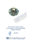
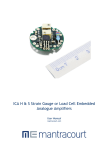
ICA5 S and A Versions
Strain Gauge or Load Cell Embedded
Analogue Amplifier
User Manual
www.mantracourt.co.uk
ICA5S and ICA5A Manual
Contents
Introduction to the ICAS and ICAH Range of In-Cell Amplifiers ................................................................ 2
Chapter 1 The ICAS and H Range ..................................................................................................... 3
Figure 1.1 Block Diagram ................................................................................................................ 3
Chapter 2 Installing The ICA5S and ICA5A .......................................................................................... 4
Pre Installation ............................................................................................................................ 4
Figure 2.1 Dimensions ................................................................................................................... 4
Power Connections ....................................................................................................................... 5
Figure 2.2 Connection Details .......................................................................................................... 5
Figure 2.3 Connection Details for Best EMC Immunity ............................................................................. 5
Table 2.1 ................................................................................................................................... 6
Output Connections ...................................................................................................................... 6
Output Shunt Resistance Formula ..................................................................................................... 6
Chapter 3 Setting Gain and Offset Values .......................................................................................... 7
Calculating the Gain Resistor (R2) ..................................................................................................... 7
Offset Resistor (R1) ...................................................................................................................... 7
Chapter 4 Calibration ................................................................................................................... 8
Figure 4.1 Connection Details for Calibration ....................................................................................... 8
Chapter 5 Troubleshooting ............................................................................................................ 9
Chapter 6 Product Care ............................................................................................................... 10
Chapter 7 Glossary ..................................................................................................................... 11
Chapter 8 Specifications .............................................................................................................. 13
Table 8.1 ICA5S – 4-20mA 2 wire Specifications .................................................................................... 13
Table 8.2 ICA5A – 4-20mA 2 wire Specifications ................................................................................... 14
Other Mantracourt Products.......................................................................................................... 15
1
Mantracourt Electronics Limited ICA5S and ICA5A User Manual
Introduction to the ICAS and ICAH Range of In-Cell Amplifiers
Two new families, the ICAS (industrial stability) and ICAH (high stability) have been introduced into the Mantracourt
range of In-Cell Amplifiers. They offer improved performance and easier installation over the original designs.
The following points detail the main changes:
The ICA1 and ICA2 output ranges have been changed to cover 0.1V to 10.1V and 0.1V to 5.1V respectively to
facilitate calibration and interpretation of the output level.
The linearity has been improved at the lower end of the scale (down to 70mV output).
Excitation is standardised at 5V DC on the ICA1,2,3,4 and 6.
The performance of the ICA family has been much improved over the operating temperature range by using
high performance, auto-zero amplifiers and low drift resistors.
The standard (‘S’) versions give a 200% improvement compared to the earlier versions.
The high performance (‘H’) versions are fitted with higher-specification resistors to offer a 400%
improvement over the earlier versions.
The user-selectable span resistor is mounted via two standard plated through holes in the printed circuit
board making it easier to change if required.
There is also provision for a second resistor (not normally fitted) to give an offset zero if required for
example, 5.1V ±5V for an ICA1.
All wire connections are via plated through holes instead of the single-sided pads used in the original design.
This allows all wires to enter from either side of the board resulting easier installation and improved joint
reliability.
Multi-layer printed circuit boards and additional filtering has been added to further improve the EMC
performance.
Faster and easier mounting/installation: The mounting hole size and position has been standardised on all
models and also provides the capacitive-coupling connection to the sensor body which further improves the
EMC performance.
The hole will accommodate a 2mm (#0-80) screw with adequate clearance for the head.
As this mounting method is compatible with our range of ‘D-Cell’ products, a single pocket design will
accept either digital or analogue conditioners.
An ATEX (Intrinsic Safety) certified version of the ICA5 will be introduced.
All variants are RoHS compliant.
All models have a reduced height of just 7.6mm. The diameter remains at 19.5mm.
A new model, the ICA6 has been introduced which will provide a ±10 Volt output from a uni-polar 15 to 28V
supply.
Non-interaction between the trimmers makes calibration easier and faster.
Mantracourt Electronics Limited ICA5S and ICA5A User Manual
2
Chapter 1 The ICAS and H Range
Figure 1.1 Block Diagram
The ICA is a Strain Gauge Amplifier, converting a strain gauge input to a Volt or mA output – otherwise known as a
Signal Conditioner.
The ICA provides a wide range of signal conditioning for Strain Gauges, Load Cells, Pressure and Torque Transducers.
Offered in 6 versions and two performance categories, ICAS and ICAH. The ICAH offers lower drift over the operating
temperature range.
ICA1
ICA2
ICA3
ICA4
ICA5
ICA6
-3
-3
-4
-3
–2
-3
wire
wire
wire
wire
wire
wire
- 0.1 to 10.1V
- 0.1 to 5.1V
- 10V / 15V supply
- 4 to 20mA
– 4 to 20mA
– 10V / 15-24V supply
This manual only deals with the ICA5 version, separate manuals exist for versions ICA1 & 2, ICA3 and ICA4.
The ICA5 is available in two versions, the standard ICA5S and the soon to be introduced ATEX (intrinsic safety)
ICA5A.
N.B. The ICA5 is designed for a 1k bridge, however 350R can be used with a reduced performance.
Transducer SENSITIVITY of between 0.5 mV/V and 55 mV/V are possible. It is optimized to 2.5 mV/V.
Sensitivity adjustment is achieved by a combination of gain (span) resistor ‘R2’ change and associated fine
adjustment by potentiometer.
Similarly transducer ZERO can be compensated for in the module. This adjustment is to compensate for slight errors
in the strain gauge and not to offset tare. The value of R1 (Figure 2.2) can be modified to increase the trim range of
the zero point.
3
Mantracourt Electronics Limited ICA5S and ICA5A User Manual
Chapter 2 Installing The ICA5S and ICA5A
Pre Installation
See Specification Details in Chapter 8 for details of Environmental Approvals.
Carefully remove the ICA unit from its shipment box. Check that the unit is complete and undamaged.
The ICA units can operated in any industrial environment providing the following limits are not exceeded
Operating Temperature
Humidity
Storage temperature
-40ºC to +85ºC
95% non condensing
-40ºC to +85ºC
The following installation practices are advised:
Minimise vibration
Do not mount next to strong electrical fields (transformers, power cables)
Ensure easy access to the module
Install electrical protection device as the unit is not internally fused
Always ensure the package is secure and protected
Figure 2.1 Dimensions
The module is designed to fit in the strain gauge pocket. Use the 2.1mm hole to secure the unit and to provide a
good ground connection.
The mounting hole will accept an M2 screw or American equivalent #0-80.
Important Note: DO NOT USE #2 screw size.
Take care when soldering cables to the pads. Use a temperature controlled soldering iron set to a maximum 330 ºC,
for no longer than 2 seconds per pad. Excessive heat or increased soldering time may result in damage to the PCB.
If changing resistor R1 or R2 do so at a workbench and not on site.
Check the relevant details for model ICA5– ensure the module matches the instructions.
The ICA5 solder pads are as shown
4 pads for the strain gauge
2 pads for power supply/signal
The fixing screw hole provides a ground connection to improve EMC performance.
Mantracourt Electronics Limited ICA5S and ICA5A User Manual
4
Power Connections
The power supply for the ICA5S should be between 7.5 and 28V
The minimum supply for the ICA5A version is 9V
Figure 2.2 Connection Details
The strain gauge cable should be attached to the solder pads as illustrated.
N.B The voltage between either of the power supply connections and the load cell chassis should not exceed 50V.
Any leakage will be greater than 10M Ohms.
Figure 2.3 Connection Details for Best EMC Immunity
The securing bolt should be used to provide a good electrical ground and mechanical support. This is important for
optimum EMC performance.
5
Mantracourt Electronics Limited ICA5S and ICA5A User Manual
Table 2.1
This typical cable data is provided for information only.
The cable should have 2 x twin twisted cables. Ideally each pair should be individually shielded and with an overall
shield.
Country
UK
Supplier
Farnell
Part No
118-2117
Description
Individually shielded twisted multipair cable (7/0.25mm)- 2 pair
Tinned copper drain. Individually shielded in polyester tape.
Diameter: 4.1mm
Capacitance/m: core to core 115 pF & core to shield 203 pF
Note: For easy connections the above 1 pair cable is recommend, however the ones below can be used:
UK
Farnell
585-646
UK
RS
626-4761
Individually shielded twisted multipair cable (7/0.25mm)- 3 pair
Tinned copper drain. Individually shielded in polyester tape.
Diameter: 8.1mm
Capacitance/m: core to core 98 pF & core to shield 180 pF
Braided shielded twisted multipair cable (7/0.2mm)- 1 pair
Miniature- twin -round Diameter: 5.2 mm
Capacitance/m: core to core 230 pF & core to shield 215 pF
The ground connection conductor should have sufficient cross-sectional area to ensure a low impedance path to
attenuate RF interference.
Output Connections
The ICA5 analogue output is 4 to 20mA. The power and signal are combined in a single pair cable, simplifying
installation.
N.B. Neither connection to the output load is electrically common to the load cell.
The following formula gives the suitable range of shunt resistance for low supply voltage operation.
Output Shunt Resistance Formula
ICA5S: the shunt resistance must be less than:
((Vsupply -7.5) / 20mA) – Rwiring
e.g. assuming 10 Ohms wiring resistance and 9V supply:
Max shunt resistance = ((9 - 7.5) / 0.02) –10 = 65 Ohms
ICA5A: the shunt resistance must be less than:
((Vsupply -9) / 20mA) – Rwiring
Mantracourt Electronics Limited ICA5S and ICA5A User Manual
6
Chapter 3 Setting Gain and Offset Values
The ICA5 (4 to 20mA) In-Cell strain gauge amplifier is supplied un-calibrated but optimized for a sensitivity of
2.5mV/V. To accommodate other sensitivities the gain resistor ‘R2’ as shown in Figure 2.2, can be changed
according to the following formulae.
N.B. a high quality component (e.g. 1% 50 ppm metal film device) should be used for optimum performance. It may
be necessary to use an E96 value for optimum trim range: -
Calculating the Gain Resistor (R2)
613.6
10 k Ohms
(mV / V ) Vexc
R2
Where mV / V is the sensitivity of the load cell (in mV/V), Vexc is the excitation voltage (in volts).
The following table gives calculated values of Vexc for various standard load cell impedances:
Load Cell Impedance
350
700
1000
1400
2000
5000
Excitation voltage (Vexc)
0.53
0.87
1.08
1.29
1.51
1.97
e.g. For a 2.5mV/V 1000 Ohm load cell : R2 = 217k Ohms – use 220k (nearest preferred value)
Use the following formulae to calculate the excitation voltage for cell impedances not given in the table:
1
(1/ Rcell ) 4.762 10 exp 6
Rx
Vexc
2.5 Rx
Rx 1300
Ohms
Volts
e.g. for a 500 Ohm load cell:
Rx = 498.8 Ohms
Excitation Voltage, Vexc = 0.693V
Offset Resistor (R1)
The value of R1 can be changed to offset the zero point, if outside the normal trimming range (±2% FS).
Its value will also depend on the impedance of the load cell. The factory-fitted value, 180k is optimised for a 1000
Ohm cell.
If a 350 Ohm cell is used, R1 should be reduced to 30k to achieve a trim range of ±2% FS
7
Mantracourt Electronics Limited ICA5S and ICA5A User Manual
Chapter 4 Calibration
Figure 4.1 Connection Details for Calibration
1. Apply the low calibration conditions (weight, force or mV/V). Set the output to 4mA using the ‘Z’ potentiometer.
2. Apply the known high calibration conditions (ideally between 75% and full scale) and adjust the ‘S’
potentiometer to give the required output current for the known input.
e.g. 16mA for 4-20mA final calibration with 75% input or 20mA if 100% input.
Mantracourt Electronics Limited ICA5S and ICA5A User Manual
8
Chapter 5 Troubleshooting
1.
a)
b)
c)
d)
e)
f)
g)
No Output
Check power supply is present and the correct polarity
Check the output connections are correct with no open circuit connections
Check terminations (ensure there are no dry joints)
Check the sensor is connected with the power off (impedance check)
Check the Excitation voltage is correct
Check the load is connected and is not open or short circuited
Check Span and Gain calibration
2. Low Output
This is when an output is present but not of sufficient magnitude to meet the required value. Remember to allow for
Tare Weight and ensure it is measured and allowed for in the output from the ICA
a) Check power supply is within specified limits (i.e. is not low – Voltage check)
b) Check the sensor is connected (typically reading 1000 Ohm across output + & -) with the power off
c) Check the Excitation voltage is at 1.1V dc for a 1k load cell (0.53V for 350R)
d) Check the calibration
e) Check the Zero (offset) is correct for the sensor, this too is a common reason for low outputs
3. High Output
This is when an output is present but higher (in span or zero) than expected.
High output is not normally a problem. It is most likely to be incorrect connections and as such the output would be
high and fixed.
a) Check the sensor is connected (Impedance check) with the power off
b) Check the Excitation voltage is at 1.1V dc (assuming a 1k load cell)
c) Check the Zero (offset)
d) Check the calibration
4. Unstable Output
This is when the output is unstable or varies. The cause could be (a) poor installation or (b) a noisy environment.
Poor Installation -This is when an output is present but higher or lower (in span or zero) than expected:
a) Check the installation for problems and repair where necessary
b) Poor termination
c) High resistance on cable leads
d) Low insulation impedance
e) Proximity to High Voltage Equipment – Transformers, Contactors, Motors etc.
Noisy Environmenta) Check if the source can be found and remove noise
b) Check the cable shielding and ensure it is correctly installed and terminated
5. Calibration
This section assumes that the unit is providing an output that is not stuck at top or bottom of the scale.
(See paragraphs 1-3 if this is the case)
Ensure you are connected to the correct sensor and not to another adjacent unit.
Ensure you have the correct calibration data from the sensor manufacturer. This must include a certified table with
offset, zero and linearity.
Ensure you have the calibration set-up correctly installed i.e. mV source and output as required.
Ensure the temperature and other environmental parameters are within specification and where necessary taken
into account when calibrating should such parameters have an effect on the calibration.
6. Fine Span (Gain) and Zero (Offset ) Adjustment Problems
If the adjustment cannot reach the maximum output desired then, check the tare is not too high.
If the potentiometer does not alter the output the unit must be repaired – remove from service.
It is always wise to check a known good ICA against the problem Installation before rejecting the suspect ICA.
9
Mantracourt Electronics Limited ICA5S and ICA5A User Manual
Chapter 6 Product Care
A worn out component, excessive use in harsh environments, an overly zealous operator; regrettably some
circumstances necessitate repair.
At Mantracourt Electronics Ltd we can't guarantee that a product will never require repairing. We can, however,
promise a repair service of exceptional quality, one which is governed by a rigorous procedure.
Detailed below is our pledge to you: a defined set of ground rules and procedures to which we will adhere. All we
ask in return is that you assist us with our procedure, such that we can maintain our promise to you. Please note
that warranty repairs may not be available on overdue accounts, and that a strict interpretation of our conditions of
trading invalidates warranty claims where late payment has occurred.
Please refer to ‘Customer Repair Service Procedure’ document – contact your supplier for a copy.
In the unlikely event you have problems with the ICA module we would advise that you take the following
precautions:The unit is installed as instructed.
Recommended spares are kept in stock. We can assist.
Sufficient expertise available for first line maintenance.
Routine maintenance checks are performed – annually is recommended.
The necessary documentation for the product is available to the maintenance personnel.
We recommend you keep on file – as a minimum
This Manual
The calibration figures for the attached sensors
A record of the ‘normal’ output – if applicable
A calibration record of the ICA
A contact phone number from the supplier for assistance
Mantracourt Electronics Limited ICA5S and ICA5A User Manual
10
Chapter 7 Glossary
AWG
Background Noise
Bipolar
Bridge Resistance
Calibration
CMR
(Common-Mode
Rejection)
Common Mode
Rejection Ratio
Drift
Excitation
Fine Adjustment
Full Bridge
Full Range Output
Gain
Ground
Linearity
Load
Load Impedance
Load Cell
Millivolt
Noise
Null
Offset
Potentiometer
Pressure
Transducer
Proportional
Outputs
11
American Wire Gauge.
The total noise floor from all sources of interference in a measurement system,
independent of the presence of a data signal. (See Noise)
The ability of a signal conditioner to display both positive and negative
readings.
The resistance measured across the excitation terminals of a Strain Gauge.
Adjustment of an instrument or compiling a deviation chart so that it’s reading
can be correlated to the actual value being measured.
The ability of an instrument to eliminate the effect of AC or DC noise between
signal and ground. Normally expressed in dB at DC to 60 Hz. One type of CMR is
specified between SIG LO and PWR GND. In differential meters, a second type
of CMR is specified between SIG LO and ANA GND (METER GND).
The ability of an instrument to reject interference from a common voltage at
its input terminals with relation to ground. Usually expressed in db (decibels).
Change of a reading/set point value over periods due to several factors
including change in ambient temperature, time and line voltage.
The external application of electrical voltage current applied to a transducer
for normal operation.
Zero and Span calibration have a Fine Adjustment to give accuracy to the
calibration. These are potentiometers P1 and P2 for Span and Zero
respectively.
A Wheatstone Bridge configuration utilizing four active elements or Strain
Gauges.
The algebraic difference between the minimum output and maximum output.
Gain is otherwise identified as SPAN. It relates to the proportional output to
the sensor input. Calibration of the ICA is determined by setting the Gain
(Span) and Offset (Zero). The amount of amplification used in an electrical
circuit.
The electrical neutral line having the same potential as the surrounding
ground.
The closeness of a calibration curve to a specified straight line. Linearity is
expressed as the maximum deviation of any calibration point on a specified
straight line during any one calibration cycle.
The electrical demand of a process expressed as power (watts), current (amps)
or resistance (ohms).
The impedance presented to the output terminals of a transducer by the
associated external circuitry.
The load cell is one of a series of STRAIN GAUGE sensors that the ICA input is
designed to accept. (Torque Sensor, Pressure & temperature transducers).
One thousandth of a volt, 10-3 volts symbol mV.
An unwanted electrical interference on the signal wires.
A condition, such as balance, which results in a minimum absolute value of
output.
Offset is otherwise identified as ZERO. Calibration of the ICA is determined by
setting the Offset (Zero) and Gain (Span).
Two potentiometers (variable resistors) are used in the ICA for fine calibration.
The Pressure Transducer is one of a series of Strain Gauge sensors that the ICA
input is designed to accept. (Torque Sensor, Load Cell and Temperature
Transducers).
The Voltage or Current outputs are calibrated to be directly proportional to the
input from the sensor. The output is, within the sensor limits, taken as linear
and no linearity compensation is required within the ICA.
Mantracourt Electronics Limited ICA5S and ICA5A User Manual
Resolution
Sensing Element
Sensitivity
Signal Conditioner
Single Card
Assembly
Span
Span Adjustment
Stability
Strain Gauge
Strain Gauge
Amplifier
Torque Transducer
Wheatstone Bridge
Zero
Zero Adjustment
Zero Offset
Zero Suppression
The input corresponding to a one-unit change in the least significant digit of
the data acquisition/display equipment. (Good resolution is not necessarily
equal to good accuracy.)
That part of the Transducer, which reacts directly in response to the input.
This is the relationship between the change in Strain Gauge input to the level
or magnitude of the output.
A circuit module that offsets attenuates, amplifies linearizes and/or filters the
signal. The ICA is essentially a Signal Conditioner –more specifically known as a
Strain Gauge Amplifier - in that it CONDITIONS (alters) the input signal from a
load cell to an electrical output.
The ICA has only the one Printed Circuit Board assembly on which all the
components are mounted. The assembly is then mounted inside an
environmentally rugged enclosure.
Span is otherwise identified as GAIN. It relates to the proportional output to
the sensor input. Calibration of the ICA is determined by setting the Span
(Gain) and Zero (Offset).
The ability to adjust the gain of a process or strain meter so that a specified
display span in engineering units corresponds to a specified signal span.
The quality of an instrument or sensor to maintain a consistent output when a
constant input is applied.
The Strain Gauge is a resistance bridge device where the bridge value alters
linearly and proportionally to the force exerted on it – be it pressure, torque or
load. The ICA is designed to convert this change in the Strain Gauge to a
proportional electrical signal.
The ICA1 & 2 is essentially a type of Signal Conditioner that it conditions
(alters) the input signal from a strain gauge to an electrical output
The Torque Transducer is one of a series of Strain Gauge sensors that the ICA
input is designed to accept.
A network of four resistance’s, an emf source, and a galvanometer connected
such that when the four resistance’s are matched, the galvanometer will show
a zero deflection or "null" reading.
Zero is otherwise identified as OFFSET. It relates to the proportional output to
the sensor input. Calibration of the ICA is determined by setting the Span
(Gain) and Zero (Offset).
The ability to adjust the display of a process or strain meter so that zero on
the display corresponds to a non-zero signal.
The difference between true Zero and an indication given by a measuring
instrument. See Zero Suppression.
The Span is Offset from Zero (Zero Suppressed) such that neither limit of the
Span will be Zero. For example, an instrument which measures a load of a
100kG Span from 400kG to 500kG is said to have 400kG Zero Suppression.
Units
AC
DC
Hz
kHz
mA
mm
SC
ICA
V
mV
Alternating Current
Direct Current
Hertz (Frequency)
kilohertz (Frequency)
milliamps
millimetres
Signal Conditioner
Strain Gauge Amplifier
Volts
millivolts
Mantracourt Electronics Limited ICA5S and ICA5A User Manual
12
Chapter 8 Specifications
Table 8.1 ICA5S – 4-20mA 2 wire Specifications
Environmental
Parameter
Supply voltage Range
Operating Temperature
Range
Storage Temperature
Range
Reverse polarity
Protection
Minimum
7.5
Typical
24
Maximum
30
Units
Volts
Notes
-40
-
85
Deg C
-40
-
85
Deg C
-30
-
-
Volts
Minimum
1.05
350
0.5
DC
-
Typical
1.11
1000
2.5
±2
±8
0.02
Maximum
1.16
5000
55
800
1000
-
Units
Volts
Ohms
mV/V
Ohms
Hz
%FR
%FR
%FR
Notes
Note 1
-
0.001
0.005
+/-%FR/Deg C
At 2.5mV/V
-
0.007
0.014
+/-%FR/Deg C
At 2.5mV/V
Measurement
Parameter
Bridge Excitation
Bridge Impedance
Bridge Sensitivity
Output load
Bandwidth
‘Zero’ adjustment
‘Span’ adjustment
Linearity
Temperature stability
‘Zero’ Temperature
Stability
‘Span’ Temperature
Stability
FR=Full Range (16mA)
Note
Note
Note
Note
Note 2
Note 3
Note 4
1: 1000 Ohm load cell – Typically 0.53V for 350 Ohm cell
2: Set by calibration resistor
3: 24V supply minimum.
4: 1000 Ohms load cell – change R1 to suit other load cell impedances.
Note: Recommended bridge impedance is 1,000 Ohms
Note: The voltage between either of the power supply connections and the load cell shield should not exceed 50V.
Any leakage will be greater than 10M Ohms.
13
Mantracourt Electronics Limited ICA5S and ICA5A User Manual
Table 8.2 ICA5A – 4-20mA 2 wire Specifications
Environmental
Parameter
Supply voltage Range
Operating Temperature
Range
Storage Temperature
Range
Reverse polarity
Protection
Minimum
9.0
Typical
24
Maximum
30
Units
Volts
Notes
-40
-
85
Deg C
-40
-
85
Deg C
-30
-
-
Volts
Minimum
1.05
350
0.5
DC
-
Typical
1.11
1000
2.5
±2
±8
0.02
Maximum
1.16
5000
55
700
1000
-
Units
Volts
Ohms
mV/V
Ohms
Hz
%FR
%FR
%FR
Notes
Note 1
-
0.001
0.005
+/-%FR/Deg C
At 2.5mV/V
-
0.007
0.014
+/-%FR/Deg C
At 2.5mV/V
Measurement
Parameter
Bridge Excitation
Bridge Impedance
Bridge Sensitivity
Output load
Bandwidth
‘Zero’ adjustment
‘Span’ adjustment
Linearity
Temperature stability
‘Zero’ Temperature
Stability
‘Span’ Temperature
Stability
FR=Full Range (16mA)
Note
Note
Note
Note
Note 2
Note 3
Note 4
1: 1000 Ohm load cell – Typically 0.53V for 350 Ohm cell
2: Set by calibration resistor
3: 24V supply minimum.
4: 1000 Ohms load cell – change R1 to suit other load cell impedances.
Note: Recommended bridge impedance is 1,000 Ohms
Note: The voltage between either of the power supply connections and the load cell shield should not exceed 50V.
Any leakage will be greater than 10M Ohms.
CE Approvals
European EMC Directive
2004/108/EC
BS EN 61326-1:2006
BS EN 61326-2-3:2006
Mantracourt Electronics Limited ICA5S and ICA5A User Manual
14
Other Mantracourt Products
www.mantracourt.co.uk
Signal Conditioning
SGA
STRAIN GAUGE AMPLIFIER
Connect up to 4 strain gauges
Proportional mA and/or Voltage output
Simple DIL switch configuration
Set Sensitivity and Low pass filter and output
Simple - Reliable - Rugged
RCA15
RACK MOUNTED INTELLIGENT
STRAIN GAUGE AMPLIFIER
Complete MULTI-CHANNEL system for Strain gauges.
Relay and/or serial outputs per channel
Multidrop serial link
19” Eurorack x 3U high.
Capability similar to the ADW 15.
High integrity / compact Data acquisition unit
LCA
IN-LINE INTELLIGENT
STRAIN GAUGE AMPLIFIER
2 Set Points
4 to 20 mA AND 0 to 10 V (isolated) outputs
RS 232/485 Communications port
On-Board easy to use Programmer
Auto tare–Auto calibrate–and much more…..
ADW15 Mantraweigh
72 mm DIN Module – Display & Controller
10 mm LED Display (Configurable)
Sensitivity from 0.5 mV to 200 mV/V
10 V @150 mA Excitation
Isolated I/O100mSec sample rate
Set Point Relays
4 to 20 mA Output
Programmable via keypad
FIELDBUS CONNECTIVITY IN TWO EXCELLENT PACKAGES
DSC The Digital Strain Card
‘D’Cell The ‘in-cell’ Digital Strain Puck
Mount this package adjacent to the strain gauge
Plug-in-and-go-sensor
Integrate the electronics with the loadcell,
remove the cost, space and bother of additional
electronics and have a direct output
provided in
REAL ENGINEERING UNITS.
Mount this package directly into the strain gauge
pocket
High accuracy
A quantum leap in the quality of measurement.
Accuracy (1 part in half a million)
Temperature compensated
Unwanted Signal noise filter
Sensor specific calibration
Elimination of induced noise on signals
ISO 9001
REGISTERED FIRM
C In the interests of continued product development, Mantracourt Electronics Limited reserves the right to alter product specifications
without prior notice.
Doc No. 517-178
15
Issue 1.4
Mantracourt Electronics Limited ICA5S and ICA5A User Manual
01.02.13