1
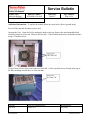
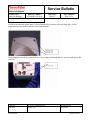
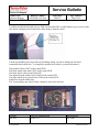
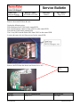
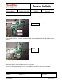
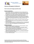
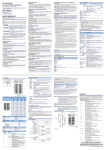
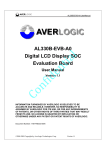
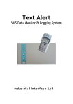
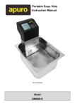
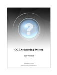
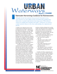
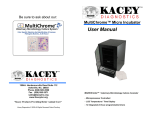
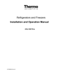
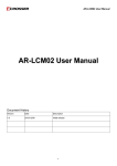
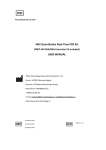
Service Bulletin
Service and Support
Product Line:
Bulletin Number:
Molecular Biology
0708-MB-AVL-0045
Model(s): HBPX2 ALL
Issue Date:
28/08/07
Page Number:
Page 1 of 6
Title:
User programs disappear after power down
Subject:
Release of new spare part (Battery Module) to resolve loss of user programs
Description:
The HBPX Thermal Cyclers contain a socket mounted battery module used to
power the SRAM that stores the users programs. The lithium energy source in
the module is not rechargeable. The battery provides back-up power after the
first time the PCB in the PX2 system is powered-up and then down. The
battery is providing back-up power through the manufacturing, shipping,
warehousing and distribution cycles. The battery is also discharging when ever
the customer powers down the PX2. The current process is to change the PCB
(P/N PCYL237).
.
Models Affected:
All HBPX2 Thermal Cyclers.
Production Range:
All
Resolution:
A new spare part is being released to allow for the replacement of the socket
mounted module as an alternative repair. The new P/N will be T00124 and
can be ordered from Asheville
AUTHOR:
CONTACT INFORMATION:
REVIEWED BY:
Mark Snow
800-843-1113
Gary Mello
Form SVC002
Revision 3/27/07
Service Bulletin
Service and Support
Product Line:
Bulletin Number:
Molecular Biology
0708-MB-AVL-0045
Model(s): HBPX2 ALL
Issue Date:
28/08/07
Page Number:
Page 2 of 6
Additional Information: To replace the module follow the steps below (Wear a ground strap):
Power off the unit and disconnect power cord.
Opening the Unit: Open the Lid by rotating the knob on the top. Remove the interchangeable block
assembly and put it to one side. Unscrew the four M4 x 12 Hex button head screws around the fan duct
using a 2.5mm hex driver
Using a 3mm A/F hex driver remove the two black M4 x 16 hex cap head screws located at the top of
the blue moulding towards the rear of the machine,
AUTHOR:
CONTACT INFORMATION:
REVIEWED BY:
Mark Snow
800-843-1113
Gary Mello
Form SVC002
Revision 3/27/07
Service Bulletin
Service and Support
Product Line:
Bulletin Number:
Molecular Biology
0708-MB-AVL-0045
Model(s): HBPX2 ALL
Issue Date:
28/08/07
Page Number:
Page 3 of 6
Carefully turn the unit upside down. Using a 3mm hex driver remove the two black M4 x 16 hex
cap head screws located towards the front of the machine,
Using a Philips screwdriver, remove the two screws that pass through the two rear feet, and remove the
rear feet,
AUTHOR:
CONTACT INFORMATION:
REVIEWED BY:
Mark Snow
800-843-1113
Gary Mello
Form SVC002
Revision 3/27/07
Service Bulletin
Service and Support
Product Line:
Bulletin Number:
Molecular Biology
0708-MB-AVL-0045
Model(s): HBPX2 ALL
Issue Date:
28/08/07
Page Number:
Page 4 of 6
Carefully turn the unit the right way up. Slide out the Peltier PSU a small distance to give access to the
rear chassis clamping screws and remove them using a 3mm hex driver.
Lift the top moulding away from the base moulding, taking care not to damage the electrical
connections that join the two. To completely separate the two halves you must disconnect:
The heated lid from CON7 on the control PCB.
The block signal cable from CON3 on the control PCB.
The block power cables from Peltier PSU.
The display/keypad module from CON10 on the control PCB.
The block sensor micro switch from CON9 on the control PCB.
Earth Wire from the baffle plate.
The Top moulding, may now be lifted completely away from the base,
AUTHOR:
CONTACT INFORMATION:
REVIEWED BY:
Mark Snow
800-843-1113
Gary Mello
Form SVC002
Revision 3/27/07
Service Bulletin
Service and Support
Product Line:
Bulletin Number:
Molecular Biology
0708-MB-AVL-0045
Model(s): HBPX2 ALL
Issue Date:
28/08/07
Page Number:
Page 5 of 6
Remove the main PCB from the unit:
Unplug the following wires:
The transformer from CON6 on the control PCB.
The communications connector from CON11 on the control PCB.
The fan from CON4 on the control PCB.
The 10 way IDC from the Peltier PSU from CON5 on the control PCB.
Locate and remove the six fixing screws for the control PCB,
Remove the PCB from the chassis and locate device IC6
IC 6
Pin 1
AUTHOR:
CONTACT INFORMATION:
REVIEWED BY:
Mark Snow
800-843-1113
Gary Mello
Form SVC002
Revision 3/27/07
Service Bulletin
Service and Support
Product Line:
Bulletin Number:
Molecular Biology
0708-MB-AVL-0045
Model(s): HBPX2 ALL
Issue Date:
28/08/07
Page Number:
Page 6 of 6
Carefully remove the top device in the stack. Noting the orientation of pin 1
SRam removed
Using a small flat blade, carefully insert between the socket and the module, pry the module up and
remove.
Module
removed
Install new module, reverse the steps above to re-assemble.
Follow the instructions on page 19 of the User Manual to set the Date and Time as needed.
AUTHOR:
CONTACT INFORMATION:
REVIEWED BY:
Mark Snow
800-843-1113
Gary Mello
Form SVC002
Revision 3/27/07