1
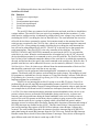
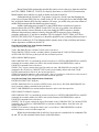
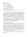
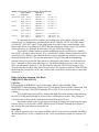
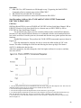
Serial I/O Routines
Serial I/O refers to the I/O (input/output) operations that occur over the serial bus. The serial port
connects the 64 and VIC to the serial bus. Several I/O devices such as disk drives and printers
can be connected to the serial bus. Each I/O device is an intelligent device that contains its own
microprocessor and ROM control program that allows the device to know how to respond to the
commands it receives over the serial bus from the 64/VIC.
During serial I/O, data is transmitted one bit at a time over the serial bus with the series
of bits normally representing a byte of data or a command. RS-232 communications also occur in
a bit by bit serial manner, but it uses separate lines for transmitting and receiving, while serial
I/O only uses one. Two other lines on the serial bus, the serial clock line and the serial attention
line, are also used during serial I/O. Within the 64 and VIC, the data and clock lines are both
divided into separate lines for incoming and outgoing signals: serial data input, serial data output,
serial clock input, and serial clock output. Only a serial attention output line is connected from
64/VIC hardware to the serial bus attention line. The unused serial attention input line is
connected to pin 9 of the user port. The serial bus has one additional signal line: serial service
request input. However, the Kernal serial I/O routines do not make use of this line
Another difference between RS-232 and serial I/O is in the number of bits that make up a
discrete unit of transmission. With RS-232, a unit can be less than eight bits, while in serial I/O a
unit is always eight bits. Each byte of serial data is transmitted and received from the low bit to
high bit direction. For example, ASCII A with a bit value of 0100 0001 is transmitted in this
sequence: 10000010.
The tables below show which CIA data port bits are used in serial I/O for the 64 and
which VIA data port bits are used in serial I/O for the VIC.
Commodore 64 Serial Port CIA Map
DD00: CIA #2 Data Port A
Bit 3 Serial attention output
Bit 4 Serial clock output
Bit 5 Serial data output
Bit 6 Serial clock input
Bit 7 Serial data input
DC0D: CIA #1 Interrupt Control Register
Bit 4 FLAG IRQ—serial service request input (not used by Kernal serial I/O routines)
VIC-20 Serial Port VIA Map
911F: VIA #1 Data Port A (without handshaking)
Bit 0 Serial clock input
Bit 1 Serial data input
Bit 7 Serial attention output
9120: VIA #2 Data Port B
CB1 Serial service request input (not used by Kernal serial I/O routines)
CB2 Serial data output
9121 VIA #2 Data Port A (with handshaking)
CA2 Serial clock output
1
The following table shows the serial I/O line functions as viewed from the serial port.
Serial Port I/O Lines
Pin Function
1
Serial service request input
2
Ground
3
Serial attention input/output
4
Serial clock input/output
5
Serial data input/output
6
Reset
The serial I/O lines are connected to all serial devices and each serial device should have
a unique address. The serial I/O lines are active low (meaning that the lines remain at +5 volts
while inactive, and bus activity is indicated by pulling a line to zero voltage). Any serial device
(including the 64/VIC) can bring the clock or data lines low. The serial attention line is used to
tell serial devices that a command is coming. No incoming signals on the attention line of the
serial port are recognized by the CIA/VIA chip—there's no serial attention input line connected
to the CIA/VIA—so any attempt by another serial bus device to bring the serial attention line
low will not be acknowledged by the 64/VIC. The 64/VIC is the only device that controls the
serial attention line. Thus, the 64/VIC is the only controller of the serial bus. The TALK,
LISTEN, UNTALK, and UNLISTEN commands are sent from the 64/VIC to one particular
serial device at a time. When the serial attention line is brought low by the 64/VIC, the serial
devices should then prepare for a command to arrive over the serial bus. The first five bits (the
low five bits) of the command contain the address of the serial device to which this command is
directed, and the last three bits specify the actual command to the serial device. With five bits, 32
possible serial devices can be addressed. However, see the caution by Michael G. Peltier in the
2542 Single Drive Floppy Disk Maintenance Manual about the maximum number of devices (five)
that should be connected to the serial bus at any one time.
Serial I/O can be performed either through BASIC commands or by calling Kernal
routines. The Kernal serial I/O routines are described later in this chapter. No examples of serial
I/O programs are included here. See the chapter on "Using Disk Storage" in Raeto Collin West's
Programming the Commodore 64 and Programming the VIC for some examples of using machine
language programs for serial disk I/O.
Serial I/O is not interrupt-driven like I/O to tape or to an RS-232 device. Tape I/O is
performed by the specific tape IRQ interrupt handling routines, and RS-232 I/O occurs from
within the NMI interrupt handler. Instead of using interrupts to determine when to send data out
or to sample data in, the Kernal serial I/O routines use interrupts (from timer B on CIA #1/timer
1 on VIA #2) to detect timeouts during the attention-response handshake when a device is not
present, to know when to perform the EOI handshake during serial receive, to detect read
timeouts, and to detect timeouts during the frame handshake at the end of each byte sent or
received. So serial I/O operates on the theory that everything is going to proceed in a timely
fashion, that the serial device is going to respond within a prescribed time period, and the
interrupts are used to enforce these time limits. During these detections of timeouts and timing of
EOI, IRQ interrupts are disabled on the 64/VIC. Thus the timer B/timer 2 interrupt that occurs
just sets the interrupt flag register at DC0D/912D to indicate a timer B/timer 2 timeout has
occurred. The serial routines that check for timeouts check the interrupt flag in DC0D/912D
rather than letting the actual IRQ interrupt from the CIA/VIA occur. Indeed, the IRQ Interrupt
Handler routine has no check for these timer B/timer 2 interrupts. Thus, the use of interrupts is
quite different with serial I/O than it is with tape or RS-232 I/O.
2
Kernal Jump Table routines that specifically send or receive data to or from the serial bus
(ACPTR, CHRIN, CHROUT, CIOUT) on a byte-by-byte basis, or LOAD/SAVE routines that
handle multiple byte transfers, are used to initiate and control serial I/O.
Although both the 64 and VIC Programmer's Reference Guides state that bringing the
serial service request (SRQ) line low results in the 64/VIC servicing the device that brought SRQ
low, no Kernal routines check for this condition. Of course, you could write your own routine to
enable SRQ interrupts and then handle any that occurred.
Another interesting item in serial I/O is that CHRIN from a serial device seems to
function almost like ACPTR. CHROUT and CIOUT are also very similar. One difference
between the routines is that a filename is only sent during the OPEN sequence. Another
difference between these routines is that by using the OPEN sequence you are limited to
secondary addresses 0-15 and device numbers 4-30. By using the TALK, TKSA, ACPTR or
LISTEN, SECOND, CIOUT sequences, it should be possible to use secondary addresses from 031 and device numbers 0-30. The following tables compare some of the serial input and output
routine sequences available on the 64/VIC.
Serial Kernal Jump Table Input Routine Similarities
TALK-TKSA-ACPTR Sequence
TALK: JSR ED09/EE14 to send $4x (TALK) to the serial device.
TKSA: JSR EDC7/EECE to send a secondary address command and do TALK-LISTEN turnaround.
ACPTR: JMP EE13/EF19 to get the byte from the serial data input line.
OPEN-CHKIN-CHRIN Sequence
OPEN: JSR ED0C/EE17 to command the current serial device to LISTEN; JSR EDB9/EEC0 to send $Fx
command, the secondary address for OPEN, and send the filename; JMP EDFE/EF04 to send an
UNLISTEN command to the serial device.
CHKIN: The X register contains the logical file number at entry. JSR ED09/EE14 to send the TALK
command to the serial device. JSR EDC7/EECE to the send secondary address and do the TALKLISTEN turnaround. Store BA in 99, the current input device.
CHRIN: If location 99 contains a value greater than 3, this is a serial device. If the device is not present, it
returns $0D. JMP EE13/EF19 to get byte from the serial data input line.
Serial Kernal Jump Table Output Routine Similarities
LISTEN-SECOND-CIOUT Sequence
LISTEN: JMP ED0C/EE17 to send $2x (LISTEN) to the serial device. SECOND: JMP EDB9/EEC0 to
send a secondary address command to the serial device.
CIOUT: JMP EDDD/EEE4 to send the buffered character on the serial data output line.
OPEN-CHKOUT-CHROUT Sequence
OPEN: JSR ED0C/EE17 to command the current serial device to LISTEN; JSR EDB9/EEC0 to send $Fx
command, the secondary address for OPEN, and send the filename; JMP EDFE/EF04 to send an
UNLISTEN command to the serial device.
CHKOUT: The X register contains the logical file number at entry. JSR ED0C/EE17 to send the LISTEN
command to the serial device. JSR EDB9/EEC0 to send the secondary address. Store BA in 9A, the
current output device.
CHRIN: If 9A contains a value greater than 3, this is a serial device. JMP EDDD/EEE4 to send the
buffered character on the serial data output line.
While the serial attention line is held low, bytes sent are considered to be commands. The
64 and VIC use the command values shown in the table below.
3
Serial Commands
$2x 001d dddd LISTEN
$3F 0011 1111 UNLISTEN all devices
$4x 010d dddd TALK
$5F 0101 1111 UNTALK all devices
$6x 011s ssss Secondary address
$Ex 1110 aaaa Secondary address for CLOSE
$Fx 1111 aaaa Secondary address for OPEN
$F1 1111 0001 SAVE memory to serial device*
$F0 1111 0000 LOAD memory from serial device*
aaaa = Secondary address (0-15) for OPEN/CLOSE
s ssss = Secondary address (0-31)
d dddd = Device address (0-30) for LISTEN and TALK.
Device 31 is pre-empted by use for UNLISTEN and UNTALK.
* As the 1541 disk drive manual states, channel numbers (secondary addresses) 0 and 1 are reserved for operating system loads
and saves, 2-14 are available, and 15 is the error channel.
As the above table indicates, you cannot send UNTALK or UNLISTEN commands just
one serial device: these commands are sent to all serial devices. The secondary address can range
from 0-31 (decimal). Notice also that there are no specific OPEN or CLOSE commands. Instead
OPEN and CLOSE are combinations of commands. OPEN is a LISTEN (possible devices 4-30),
followed by the $Fx OPEN secondary address, followed by the filename, followed by an
UNLISTEN to all devices. CLOSE is a LISTEN (possible devices 4-30), followed by the $Ex
CLOSE secondary address. Notice that OPEN for any device in its final step automatically
causes all serial devices to unlisten. It seems that only devices 0-30 are valid for LISTEN and
TALK, and 4-30 for OPEN, because device 31 is preempted for indicating the UNLISTEN and
UNTALK commands, and devices 0-3 are screened by the 64/VIC Kernal routines for OPEN to
indicate the keyboard, tape, screen, and RS-232 devices. The TALK and LISTEN routines do not
screen for device numbers 0-3. Notice that you can use a secondary address of 0-31 for TKSA
and SECOND, while you are limited to 0-15 for OPEN and CLOSE.
The Kernal serial routines also apparently prevent secondary addresses >= 128 decimal,
$80, from being sent for serial OPEN, LOAD, or SAVE.
Where to Get More Information
Serial I/O is a topic that could easily fill an entire book. This chapter discusses the Kernal serial
I/O routines, but doesn't get into specific details about disk drives and printers. The Commodore
1541 disk drive is extensively covered in Inside Commodore DOS by Immers and Neufeld and in
The Anatomy of the 1541 Disk Drive from Abacus Software, which contains an interesting
program that allows spooling of files directly from the disk to the printer while your 64/VIC is
busy doing other things. The program essentially commands the printer to listen and the disk to
talk. The hardware aspects of the 1541 are covered in the 1542 Single Drive Floppy Disk
Maintenance Manual by Michael G. Peltier. Also see the chapters about disk I/O in Raeto Collin
West's Programming the VIC and Programming the Commodore 64, both from COMPUTE!
Books. The Commodore VIC-1541 User's Manual and VIC-1525 User's Manual are also
occasionally useful. Also, the Commodore 64 Programmer's Reference Guide contains diagrams
and timings of serial I/O functions on pages 364-65.
The following table illustrates how the various values for the serial attention, clock, and
data lines may be set or read. These values indicate the actual setting of the line to high or low at
the serial data port.
4
Reading and Setting the Serial Clock, Data, and Attention Lines
Logic Value at
Where Set or
Line
Serial Port
Attention Out High — False = 1
Read: 64
DD00 bit 3 = 0
VIC
91 IF bit 7 = 0
Low = True = 0
DD00 bit 3 = 1
91 IF bit 7 = 1
Clock In
High = False = 1
Low = True = 0
DD00 bit 6 = 1
DD00 bit 6 = 0
91 IF bit 0 = 1
91 IF bit 0 = 0
Data In
High = False = 1
DD00 bit 7 = 1
91 IF bit 1 = 1
Low — True = 0
DD00 bit 7 = 0
91 IF bit 1 = 0
High = False = 1
DD00 bit 4 = 0
Low = True = 0
DD00 bit 4 = 1
CA2 control = 111
High = False = 1
Low = True = 0
DD00 bit 5 = 0
DD00 bit 5 = 1
CB2 control = 110
CB2 control = 111
Clock Out
Data Out
In examining the serial I/O routines, just looking at the code without referring to other
sources is not very enlightening. Jim Butterfield's article "How the VIC/64 Serial Bus Works"
(COMPUTE!, July 1983, pages 178-84) helps make the serial I/O logic comprehensible. Also,
Raeto Collin West's Programming the PET/CBM (like subsequent volumes on the VIC and 64)
clarifies the active low principle in which true is low (0), while false is high (1).
The serial I/O routines perform various handshaking sequences between the controller
(the 64/VIC), the talker (either the 64/VIC or a serial device), and the listeners (either the 64/VIC
or serial devices). Whenever the controller needs to send a command to a serial device, it brings
the serial attention line low. The actual transmission of a byte of data and the handshaking
sequences that occur for the data byte transfer are discussed in this chapter; see the Send Serial
Byte: Command or Data routine and Figure 8-3. The EOI handshake sequence is also covered
there, and illustrated in Figure 8-2. The EOI sequence when the 64/VIC is the listener is also
covered in the Receive Byte from Serial Device routine. The sequence called the TALK-LISTEN
turnaround that converts the 64/VIC into a listener and a serial device into the talker is described
in Figure 8-4.
Bring Serial Bus Attention Line High
EDBE/EEC5-EDC6/EECD
Called by:
Falls through from EDBB/EEC2 in Send Secondary Address After LISTEN, JSR at
EDD0/EED7 in Send Secondary Address After TALK and Do TALK-LISTEN Turnaround, JSR
at EF03/EF09 in Send UNLISTEN Command, JSR at F281/F33A in Open Serial Output
Channel.
This routine brings the serial bus attention line high. The serial attention output line from
the CIA/VIA chip passes through an inverter before reaching the serial port. Thus, setting the
CIA/VIA pin low (0) brings the serial attention line high at the serial port.
No separate routine exists for the converse function of bringing the serial attention output
line low. However, see the code at EDF3/EEF9 in Send UNTALK Command for a sample of
how to bring the serial attention output line low.
Operation:
64: AND the contents of the CIA register at DD00 with $F7 and store the result back into DD00,
thus turning off bit 3 in CIA #2 data port A. Bit 3 is the serial attention output line from the CIA
chip.
5
VIC: AND the contents of the VIA register at 91 IF with $7F and store the result back
into 91 IF, thus turning off bit 7 in VIA #1 data port A. Bit 7 is the serial attention output line
from the VIA chip.
Bring Serial Bus Data Line High
EE97/E4A0-EE9F/E4A8
Called by:
JSRs at ED24/EE2E and ED3A/EE43 in Do Attention Handshake with Serial Device, JSRs at
ED41/EE4A and ED7A/EE88 in Send Serial Byte: Command or Data, JSR at EE2A/EF26 in
Receive Byte from Serial Device, JMP at EE10/EF16 in Send UNLISTEN Command.
This routine brings the serial bus data line high. The serial data output line from the
CIA/VIA chip passes through an inverter before reaching the serial port. Thus setting the
CIA/VIA pin low (0) brings the serial data line high at the serial port.
Operation:
1. 64 :LDA DD00 (CIA #2 data port A). VIC: LDA 912C (VIA #2 peripheral handshaking
control register).
2. AND $DF (binary 1101 1111) to turn off bit 5.
3. 64: STA DD00 to set bit 5 of the port, serial data out, to 0. VIC: STA 912C to hold the CB2
handshaking line low. Data port bit 5 of CIA #1 of the 64 or the CB2 line of VIA #2 of the
VIC then passes through an inverter to reach the serial port data output line.
Bring Serial Bus Data Line Low
EEA0/E4A9-EEA8/E4B1
Called by:
JSR at ED75/EE83 in Send Serial Byte: Command or Data, JSR at EDCD/EED4 in Send
Secondary Address After TALK and Do TALK-LISTEN Turnaround, JSRs at EE47/EF45 and
EE76/EF75 in Receive Byte from Serial Device.
This routine brings the serial bus data line low. The serial data output line from the
CIA/VIA chip passes through an inverter before reaching the serial port. Thus setting the
CIA/VIA pin high (1) brings the serial data line low at the serial port.
Operation:
1. 64: LDA DD00 (CIA #2 data port A). VIC: LDA 912C (VIA #2 peripheral handshaking
control register).
2. ORA $20 (binary 0010 0000) to turn on bit 5.
3. 64: STA DD00 to set bit 5 of the port, serial data out, to 1. VIC: STA 912C to hold the CB2
handshaking line high.
Bring Serial Bus Clock Line High
EE85/EF84-EE8D/EF8C
Called by:
JSR at ED2B/EE35 in Do Attention Handshake with Serial Device, JSRs at ED49/EE53 and
ED7D/EE8B in Send Serial Byte: Command or Data, JSR at EDD3/EEDA in Send Secondary
Address After TALK and Do TALK-LISTEN Turnaround, JSR at EE0D/EF13 in Send
UNLISTEN Command, JSR at EE18/ EF1E in Receive Byte from Serial Device, JSR at FE2E in
System Reset (VIC).
6
This routine brings the serial bus clock line high. The serial clock output line from the
CIA/VIA chip passes through an inverter before reaching the serial port. Thus, setting the
CIA/VIA pin low (0) brings the serial clock line high at the serial port.
Operation:
1. 64: LDA DD00 (CIA #2 data port A). VIC: LDA 912C (VIA #2 peripheral handshaking
control register).
2. 64: AND $EF (binary 1110 1111) to turn off bit 4. VIC: AND $FD (binary 1111 1101) to
turn off bit 1.
3. 64: STA DD00 to set bit 4 of the port, serial clock out, to 0. VIC: STA 912C to hold the
CA2 handshaking line low.
Bring Serial Bus Clock Line Low
EE8E/EF8D-EE96/EF95
Called by:
JSR at ED37/EE40 in Do Attention Handshake with Serial Device, JSR at ED5F/EE6C in Send
Serial Byte: Command or Data, JSR at EDF0/EEF6 in Send UNTALK Command, JSR at FF36
in System Reset (VIC).
This routine brings the serial bus clock line low. The serial clock output line from the
CIA/VIA chip passes through an inverter before reaching the serial port. Thus, setting the
CIA/VIA pin high (1) brings the serial clock line low at the serial port.
Operation:
1. 64: LDA DD00 (CIA #2 data port A). VIC: LDA 912C (VIA #2 peripheral handshaking
control register).
2. 64: ORA $10 (binary 0001 0000) to turn on bit 4. VIC: ORA $02 (binary 0000 0010) to turn
on bit 1.
3. 64: STA DD00 to set bit 4 of the port, serial clock out, to 1. VIC: STA 912C to hold the
CA2 handshaking line high.
Read Serial Data In and Serial Clock In
EEA9/E4B2-EEB2/E4BB
Called by:
JSRs at ED44/EE4D, ED50/EE5A, ED55/EE60, ED5A/EE66, and EDA6/EEAC in Send Serial
Byte: Command or Data, JSR at EDD6/EEDD in Send Secondary Address After TALK and Do
TALK-LISTEN Turnaround, JSRs at EE1B/EF21 and EE37/EF35 in Receive Byte from Serial
Device.
On the 64, this routine first forces CIA #2 data port A, DD00, to stabilize, then loads the
accumulator from DD00 and does an ASL. This ASL leaves the bit from the serial data input line
in the carry flag of the status register and the bit from the serial clock input line in the high bit of
the accumulator.
On the VIC, this routine first forces VIA #1 data port A, 91 IF, to stabilize, then loads the
accumulator from 91 IF and does a LSR. This LSR leaves the bit from the serial clock input line
in the carry flag of the status register and the bit from the serial data input line in the low bit of
the accumulator.
7
The serial data and clock input lines from the serial port to the CIA/VIA chips do not
pass through any inverters. Thus, reading a value of 1 indicates the corresponding serial line is
high, and reading a value of 0 indicates the corresponding serial line is low.
Operation:
1. Wait for DD00/911F to stabilize by loading its value into the accumulator and comparing
this value to the current value in DD00/911F until the two are the same.
2. 64: ASL to shift the bit for the serial data input line into the carry bit and the bit for the serial
clock input line into the high bit of the accumulator.
3. VIC: LSR to shift the bit for the serial data input line into the low bit of the accumulator and
the bit for the serial clock input line into the carry bit.
Send LISTEN Command to Device
ED0C/EE17-ED10/EE1B
Called by:
JMP from Kernal LISTEN vector at FFB1, JSR at F648/F6E0 in Send Secondary Address for
CLOSE, JSR at F27A/F333 in Open Serial Output Channel, JSR at F3E3/F49F in Send OPEN,
LOAD, or SAVE Command to Device, JSR at F60D/ F6A5 in Save to Serial Device.
This routine prepares the accumulator, which contains the device number, to send a
LISTEN command to the device. The device number should be 0-30. RS-232 interrupts are
disabled, then this routine falls through to the Send Serial Control Character routine.
Operation:
1. The accumulator, which contains the current device number in the low five bits, is ORed
with $20 (binary 0010 0000) to set bits 5-7 to 001 to indicate a LISTEN command.
2. JSR F0A4/F160 to disable RS-232 interrupts.
3. Fall through to ED11/EE1C , which is the routine to send a serial command.
Do Attention Handshake with Serial Device
ED11/EE1C-ED3F/EE48
Called by:
Fall through from ED10/EE1B after Send TALK Command to Device or Send LISTEN
Command to Device, JSR at EE00/ EF06 in Send UNTALK Command or Send UNLISTEN
Command; alternate entry at ED36/EE40 by JSR at EDBB/EEC2 in Send Secondary Address
After LISTEN, JSR at EDC9/EED0 in Send Secondary Address After TALK and Do TALKLISTEN Turnaround.
If the serial deferred flag indicates that a character is buffered to be sent on the serial bus,
the end-or-identify (EOI) handshake and the buffered character are sent on the bus before the
command (control character) is sent. Also, the serial deferred flag and the EOI flag are then
turned off.
The command in the accumulator at entry, which had been temporarily saved on the
stack, is stored in 95, the serial buffered character. This buffered character is used later in the
Send Serial Byte routine when it is sent as a command with the serial attention line held low.
Next, the attention request sequence in Figure 8-1 is performed by the controller (the 64/VIC) to
inform the serial devices that a command is coming.
8
If the routine is entered at the alternate point, ED36/EE40, from the routines to send a
secondary address after TALK or LISTEN, only steps 3, 4, and 5 in Figure 8-1 are performed,
since the serial attention line should still be low.
Once step 5 in Figure 8-1 is finished, this routine falls through to the Send Serial Byte
routine at ED40/EE49 where the Send Serial Byte routine expects to find that a serial device has
responded to the attention request by bringing the serial data line low. If it doesn't find this
condition, it assumes the device is not present.
1.
2.
3.
4.
5.
Allow serial data line to go high.
Bring serial attention line low.
Bring serial clock line low.
Allow serial data line to go high.
Delay one millisecond. Listening devices must bring the data line low within this period to be recognized as
present on the bus.
One interesting question about the routine on the VIC is why the delay of one millisecond
is done with IRQ interrupts enabled (the SEI is not until EE49). Although it probably is unlikely
an interrupt would occur between the one millisecond delay and the following instruction, it is
possible and could force a false device-not-present condition. Indeed, on the 64 this oversight is
corrected by inserting the SEI before the one millisecond delay and also before bringing the
clock line low and allowing the data out to go high.
If this routine is entered from falling through from the serial send TALK command or the
serial send LISTEN command, the TALK or LISTEN command is placed in the serial buffered
character location to be sent on the serial data output line. Bringing the serial attention line low
causes all devices on the serial bus to listen for a command. Valid device addresses for the
command are 0-30. The listening devices on the serial bus can check the first five bits of the
command to see if they are the device to which this command is being sent. If the device number
is 31, all serial devices are being addressed for an UNLISTEN or UNTALK command. The
serial device that recognizes its address then reads the command from the three high bits of the
9
command.
For the alternate entry points for sending a secondary address after LISTEN or TALK,
the serial device should still be listening under attention and should read a secondary address of
0-31 from the lower five bits and read the secondary address command identifier in the three
high bits.
Operation:
1. If the serial output deferred flag, 94, has its high bit off, branch to step 5.
2. If the serial output deferred flag, 94, has its high bit on, the Send Serial Byte Deferred
routine at EDDD/EEE4 has been executed to set this flag. The flag indicates a character is
waiting to be sent. If the serial device is currently listening, the flag will be set. Set the high
bit of the end-or-identify (EOI) flag, A3, to 1.
3. JSR ED40/EE49 to send to the serial bus the EOI handshake and the buffered character.
4. Clear the high bits of 94 and A3 to indicate no character is awaiting transmission and the
EOI handshake is not to be done.
5. Store the value from the accumulator on entry to this routine in 95, the serial buffered
character.
6. 64: Disable IRQ interrupts.
7. JSR EE97/E4A0 to bring the 64/VIC serial data output line high. This will allow the serial
bus data line to go high.
8. The BNE at ED29/EE33 is an unconditional branch because the previous JSR EE97/E4A0
ANDs the accumulator with $DF (binary 1101 1111). Thus, a value of $3F (0011 1111)
could never remain in the accumulator upon return from the JSR, and hence the CMP $3F is
never equal to the accumulator. Both the 64 and the VIC have this apparent bug. It is unclear
what condition Commodore was trying to check for with this comparison for $3F, but if a
match would have been found, a JSR EE85/EF84 to allow the serial clock line to go high
would have been executed.
9. Set the 64/VIC serial attention output line low to bring the serial bus attention line low. On
the 64, store a 1 in bit 3 of DD00, the serial attention output line. On the VIC, store 1 in bit 7
of 91 IF, the serial attention output line. Remember that the lines from the CIA/VIA chip go
through an inverter before reaching the serial port.
10. ED36/EE40: Disable IRQ interrupts on the 64 only. JSR EE8E/EF8D to bring the serial
clock output line low.
11. JSR EE97/E4A0 to bring the 64/VIC serial data output line high, allowing the serial bus data
line to go high.
12. JSR EEB3/EF96 to delay one millisecond (1000 microseconds). On the VIC, VIA #2 timer
A is used to generate an interrupt after counting one millisecond. On the 64, a delay loop of
instructions that takes one millisecond to execute is used.
13. Fall through to the Send Serial Byte: Command or Data routine at ED40/EE49.
Send Serial Byte: Command or Data
ED40/EE49-EDAC/EEB3
Called by:
JSR at ED19/EE24 and fall through from ED3D/EE46 in Do Attention Handshake with Serial
Device, JSR at EDE7/EEEE in Send Serial Byte Deferred.
This routine is called to send either a command or a data byte on the serial data output
line. The data output line is from bit 5 of DD00 CIA #2 data port A on the 64, and from the CB2
handshaking line of VIA #2 port B on the VIC.
10
The 64/VIC first makes sure that it is not holding the data line low. The routine then tests
the data line, and if it is not low, the addressed serial device is not responding and is considered
not present.
If the data line is low, the device has responded and a byte can be sent to it. If the EOI
flag, A3, has its high bit on, indicating this will be the last data byte to be sent, the EOI
handshake shown in Figure 8-2 is performed before sending the buffered character.
Figure 8-2. EOI Handshake Sequence
1. The talker allows the clock line to go high when ready to send.
2. The listener allows the data line to go high when ready to receive.
3. If the talker has not brought the clock line low within 200 usec, the listener assumes this is an EOI handshake.
To confirm this, the listener brings the data line low again for 60 usec, then brings it high again.
4. To confirm the EOI handshake, the talker must not bring the clock line low within 60 usec.
Rather than the talker bringing the clock line low as it does when it is ready to transmit
normal bytes of data, the talker just loops waiting for the data line to go high. The data line goes
high when the listener is ready to receive data. The listener can hold off indefinitely allowing the
data line to go high until it is finally ready to receive data. The listener must monitor the clock
line, and if the talker does not bring the clock line low within 200 microseconds, it is notifying
the listener that the EOI sequence is to be performed and that the next byte is the last byte of the
file. The listener confirms the EOI sequence by bringing the data line low for at least 80
microseconds (for an external listener) or 60 microseconds (if the 64/VIC is the listener), then
allowing the data line to go high again. This routine for the 64/VIC watches for this sequence of
data line low, data line high to complete the EOI handshake. Then the final data byte is
transmitted in normal fashion, as shown in Figure 8-3.
11
Figure 8-3. Serial Byte Transmission and Handshake
1. The talker allows the clock line to go high when ready to send.
2. The listener allows the data line to go high when ready to receive. If the talker does not respond within 200 usec,
perform EOI handshake (see Figure 8-2).
3. The talker brings the clock line low to signal the start of transmission.
4. The talker sets the data line low for a bit value of 0 or high for bit value of 1.
5. The talker then brings the clock line high to alert the listener that a valid bit is present on the data line. The
listener must read the data line before the talker pulls the clock line low again to set the next bit value.
6. The talker brings the clock line low and the data line high between bits.
7. After all eight data bits have been sent, the listener must bring the data line low within 1000 usec to assure the
talker that the byte was successfully received.
The talker brings the clock line low after the listener has signaled it is ready to receive
data by bringing the data line high. The talker brings the clock line low within 200 microseconds
if the EOI handshake is not to be done. If the EOI handshake has been sent, the talker brings the
clock line low within 60 microseconds after the listener has brought the data line high to
complete the EOI handshake. When the talker brings the clock line low, either for EOI or nonEOI, the talker is ready to send the actual bits for this byte of data.
The routine then sets the serial byte data transfer counter, A5, to 8. The byte is sent one
bit at a time from low to high . The data output line is set high for a bit value of 1 and low for a
bit value of 0. Each bit has a set up time of around 70 microseconds during which time the clock
line is held low by the talker. Once the talker is ready to send the bit, it releases the clock line to
high to signal to the listener that the listener should sample the data line for the value of this bit.
The listener typically samples the data line within 20 microseconds. However, if the listener is
the 64, the 6567 VIC-II chip's cycle stealing for video matrix access or sprite access requires that
a minimum of 60 microseconds be allowed for the 64 to sample the data line. Between each bit
the data line should be high and the clock line held low. If the serial data input line is low
between bits, this routine branches to the read/write timeout status routine.
For each bit that is sent, the serial data transfer counter, A5, is decremented. It continues
sending bits until all eight bits have been sent or unless a read/write timeout occurs.
Once the A5 counter reaches zero, indicating all eight bits have been sent, the computer
sets CIA #1 timer B/VIA #2 timer 2 to $0400. Then it loops, waiting for the serial data input line
12
to go low. The serial data input line is brought low by the listener to indicate it has accepted the
byte. If the serial data input line does not go low within this countdown of $0400 (1000
microseconds), the timer B/timer 2 interrupt that occurs indicates a read/write timeout called a
frame error for this byte. If the serial data input line goes low within 1000 microseconds, the
listener has accepted the data. In this acceptance case, the computer will enable IRQ interrupts
and RTS.
During this routine IRQ interrupts are disabled. When IRQ interrupts are disabled, any
IRQ interrupt that occurs will not be serviced by the IRQ interrupt handler. However, by
checking the flag of the interrupt status register, you can still detect if a timer B/timer 2 interrupt
occurred. By this method, even though IRQ interrupts are disabled, interrupts can still occur and
be serviced.
Operation:
1. Disable IRQ interrupts.
2. JSR EE97/E4A0 to bring the serial data output line high. This will allow the serial bus data
line to go high.
3. JSR EEA9/E4B2 to sample the status of the serial data input line. If the serial data input line
has not been brought low by the listener, BCS to EDAD/EEB4 to set the status word, 90, to
indicate a device not present error condition.
4. JSR EE85/EF84 to bring the serial clock output line high.
5. If A3, the EOI flag, has its high bit off, branch to step 8. If the high bit is on, perform the
EOI handshake (see Figure 8-2) as this byte to be sent will be the last data byte for a file.
6. Loop until the serial data input line is brought high by the listener.
7. Loop until the serial data input line is brought low by the listener.
8. Loop until the serial data input line is brought high by the listener.
9. JSR EE8E/EF8D to set the serial clock output line low.
10. Set the serial byte data transfer counter, A5, to $08.
11. Force DD00 (CIA #2 data port A)/911F (VIA #1 data port A) to stabilize.
12. If the serial data input line is low (0) between data bits, branch to EDB0/EEB7 to set
read/write timeout status.
13. ROR 95, the serial buffered character, rotating the low bit into the carry.
14. If the carry is clear after the ROR, JSR EEA0/E4A9 to send a 0 by holding the serial data
output line low.
15. If the carry is set after the ROR, JSR EE97/E4A0 to send a 1 by holding the serial data
output line high.
16. JSR EE85/EF84 to set the serial clock output line high. Then delay for four NOP
instructions (about eight microseconds). When you combine the time required for these NOP
instructions with the time for the following LDA DD00/912C, AND $DF, ORA $10/$02,
STA DD00/912C, you see that the serial clock output line is held high for about 20 cycles.
These 20 cycles (20 microseconds) give the listener time to sample the data line.
17. Use the instructions just mentioned in step 16 to bring the serial clock output line low and
the serial data output line high.
18. Decrement the serial byte transfer counter, A5.
19. If all the bits in this byte are not yet sent (if A5 is not 0), branch to step 11 to check for a
timeout between bits (and to send the next bit if no timeout occurred).
20. After all eight bits have been sent, set CIA #1 timer B/VIA #2 timer 2 to $0400 to set a
delay of approximately 1 millisecond or 1000 microseconds. For the VIC, storing the $04 in
9129, the high byte of the latch value for timer 2, will load the counter from the latch values,
13
clear the VIA interrupt register, and start the timer countdown. However, for the 64 you
must separately order timer B to load its counter from the latches and start counting by
storing $19 into DC0F, the control register for timer B. Also, it is necessary to LDA DC0D
to clear any pending timer B interrupts.
21. If a timer B/timer 2 interrupt occurs (determined by looking at DC0D/912D, the interrupt
flag register), branch to EDB0/EEB7, the Set Status Word routine, to indicate a frame error
condition.
22. If the serial data input line stays high, loop to step 21.
23. If the listener brings the serial data line low before the timer B/timer 2 interrupt occurs (i.e.,
within one millisecond), then it is acknowledging that the byte has been received, so CLI
and RTS.
Send OPEN, LOAD, or SAVE Command to Device
F3D5/F495-F408/F4C6
Called by:
JSR at F37F/F43F in OPEN Execution, JSR at F4C8/F56A in Load or Verify from Serial
Device, JSR at F605/F69D Save to Serial Device.
For OPEN, LOAD, or SAVE operations to a serial device, the current device is
commanded to listen, then the secondary address and the filename are sent on the serial bus.
Finally, all devices on the serial bus are commanded to unlisten.
The secondary address must be less than 128 (decimal) and the filename must contain at
least one character.
Before sending the secondary address, this routine ORs the secondary address with $F0.
Thus, only secondary addresses of 0-15 are valid for OPEN, LOAD, or SAVE. A secondary
address of 0 indicates a LOAD operation, and a secondary address of 1 specifies a SAVE.
Secondary addresses 2-15 are available for OPEN.
Entry requirements:
B9 should hold the current secondary address. B7 should hold the number of characters in
filename. BA should hold the current device number. (BB) should point to the current filename.
(These values can be established using the Kernal SETLFS and SETNAM routines.)
Operation:
1. If B9, the current secondary address, >= $80 (128 decimal), branch to step 12. Only
secondary addresses < $80 (128) are acceptable for OPEN, LOAD, or SAVE.
2. If there are no characters in the filename, branch to step 12. B7 contains the number of
characters in the filename.
3. 64: Store 0 in 90 to clear the I/O status indicator.
4. LDA BA, the current device number.
5. JSR ED0C/EE17 to send a LISTEN command to the current device. The serial attention
output line is brought low to send the LISTEN command, and it will remain low upon
return.
6. LDA B9, the secondary address, then ORA $F0 to prepare to send the secondary address for
OPEN, SAVE, or LOAD.
7. JSR EDB9/EEC0 to send the secondary address to the device. The attention line is still low
from step 5 when the subroutine is called. However, the serial attention output line will be
set high upon return. Thus, the following filename is sent as regular bytes of data, not as a
command. (This is contrary to the information about how filenames are sent as commands in
14
the article "How the VIC/64 Serial Bus Works" by Jim Butterfield, COMPUTE! 1983.)
Test bit 7 of 90, the I/O status word. If bit 7 is set to 1, the preceding subroutine detected
that the specified device is not present. In this case, pull the current return address from the
stack so that the JMP to F707/F78A to display the DEVICE NOT PRESENT error message
will RTS to the routine that called for the OPEN, SAVE, or LOAD.
9. If the device is present, see if there are any characters in the filename. If not, branch to step
11.
10. If the filename contains characters, go through a loop that gets the next character in the
filename and outputs this character on the serial bus until all characters in the filename have
been transmitted. JSR EDDD/EEE4 to send each character as a byte of data.
11. JMP F654/JSR EF04. At F654 (on the 64), do a JSR EDFE. These instructions on the 64 and
the VIC command all devices on the serial bus to unlisten.
12. CLC and RTS.
8.
Send Secondary Address After LISTEN
EDB9/EEC0-EDBD/EEC4
Called by:
JMP from Kernal SECOND vector at FF93, JSR at F286/F33F Open Serial Output Channel, JSR
at F3EA/F4A6 in Send OPEN, LOAD, or SAVE Command to Device, JSR at F612/ F6AA in
Save to Serial Device, JSR at F651/F6E9 in Send Secondary Address for CLOSE.
This routine stores the secondary address passed in the accumulator in 95, the serial
buffered character, and does a JSR to ED36/EE40 to send the secondary address to the serial bus
as a command. Finally, it falls through to EDBE/EEC5 to bring the serial attention output line
high, the setting for transmitting normal data bytes.
Entry requirements:
The accumulator should hold the secondary address to be sent.
Operation:
1. STA 95, saving the secondary address in the serial buffered character location.
2. JSR ED36/EE40 to bring the serial clock output line low to indicate the talker is ready to
send another byte, delay one millisecond, and send the character in 95 to the serial data
output line. The serial attention output line should be set low when calling the subroutine, so
that the character in 95, the secondary address, will be considered to be a serial command.
3. Fall through to the routine at EDBE/EEC5 to bring the serial attention output line high.
Send Serial Byte Deferred
EDDD/EEE4-EDEE/EEF5
Called by:
JMP from Kernal CIOUT vector at FFA8, JSR at F3FE/F4BA in Send OPEN, LOAD, or SAVE
Command to Device, JSRs at F61C/F6B4, F621/F6B9, and F62B/F6C3 in Save to Serial Device,
JMP at F1D8/F288 in Determine Output Device.
This routine to send a character to the serial bus maintains a one-byte buffer, 95. The
character to be sent is stored in this buffer.
This routine first tests a flag, 94, which indicates whether the buffer, 95, already contains
a character. If the buffer contains a character, first it sends the buffered character in 95 to the
serial bus. Then it stores the current byte in the buffer, 95. If the buffer is empty at entry, it
15
simply stores the character to be sent in the buffer, 95.
Operation:
1. See if the high bit of the serial deferred flag, 94, is set. If so, branch to step 3.
2. If no character is in the buffer, set the high bit of 94 by setting the carry and rotating the
carry into bit 7 (ROR 94). Then branch to step 6.
3. Push the byte to be buffered onto the stack.
4. JSR ED40/EE49 to send the byte in 95, the serial deferred character, over the serial data
output line.
5. Pull the byte to be buffered from the stack.
6. Store the byte in 95, the serial deferred character.
7. CLC and RTS.
Set Status Word
EDAD/EEB4-EDB8/EEBF
Called by:
BCS at ED47/EE51 in Send Serial Byte: Command or Data; alternate entry at EDB0/EEB7 by
BCC at ED6F/EE7D and BNE at EDA4/EEAA in Send Serial Byte: Command or Data; alternate
entry at EDB2/EEB9 by JMP at EE44/EF42 Receive Byte from Serial Device.
Set 90, the I/O status word, to indicate an error condition. The condition indicated
depends on the entry point:
EDA0/EEB4: device not present.
EDB0/EEB7: read or write timeout.
EDB2/EEB9: read timeout.
Clear the carry, enable IRQ interrupts, bring the serial attention output line high, the
serial clock line output line high, and the serial data output line low.
Operation:
1. EDAD/EEB4: LDA $80 and fall through to step 3 by using a dummy BIT instruction.
2. EDB0/EEB7: LDA $03.
3. EDB2/EEB9: JSR FE1C/FE6A to set the I/O status word with ORA 90, STA 90.
4. Enable IRQ interrupts and clear the carry.
5. Branch to EE0E/EF09 to bring the serial attention output line high, enter a short delay loop,
bring the serial clock output line high, and bring the serial data output line low.
Delay One Millisecond
EEB3/EF96-EEBA/EFA2
Called by:
JSR at ED3D/EE46 in Do Attention Handshake with Serial Device.
For the 64, a series of instructions is executed that takes approximately one millisecond.
For the VIC, timer 2 of VIA #2, the timer count, is initialized to $0400. From this initial
value, timer 2 takes approximately one millisecond to countdown to zero and generate an
interrupt.
Operation:
For the 64:
1. TXA (2 cycles).
2. LDX $B8 (2 cycles).
16
3.
4.
5.
6.
DEX (2 cycles X 184 times = 368 cycles).
BNE to step 3 (3 cycles X 184 times = 552 cycles).
TAX (2 cycles).
RTS (6 cycles).
The JSR to call this routine also takes 6 cycles. Thus, for the 64 the total number of
cycles is 6 + 2 + 2 + 368 + 552 + 2 + 6 = 938 cycles, which when divided by the 64's clock
frequency of 1,022,370 cycles per second is 917 microseconds, or approximately one
millisecond.
For the VIC:
1. LDA $04.
2. STA 9129, VIA #2 high byte of timer 2 counter. When this STA is done, the timer 2
interrupt flag for VIA #2 is cleared, the low latch of the counter is transferred to the low
counter, and the counter begins decrementing at the system clock rate.
3. LDA 912D, VIA #2 interrupt flag register.
4. AND $20.
5. BEQ to step 3 as long as the timer 2 flag has not been set.
6. RTS.
A timer 2 value of $0400 counts down at the system clock rate. $0400 = 1024 decimal,
and 1024 cycles divided by 1,022,370 cycles per second is 1001 microseconds, approximately 1
millisecond.
Save to Serial Device
F5FA/F692-F641/F6D9
Called by:
Falls through from Determine Device for SAVE routine at F5ED/F685.
To save to a serial device, a filename must be specified. If no filename is given, jump to
the error routine to display the MISSING FILE NAME error message and exit.
Send the LISTEN command to the current serial device, send the secondary address
command of $61 to indicate a SAVE operation. Then, if the device is present, send all the
characters in the filename. If the device is not present, exit with the DEVICE NOT PRESENT
error message.
Set the pointer to the current byte to save, (AC), from the starting address to be saved.
This starting address is then sent over the serial bus, first AC and then AD. The address in (AC )
is incremented after each byte is sent to the serial device. When the address in these bytes equals
the address in (AE), the pointer to the end of the memory being saved + 1, the save is complete.
When the save is complete, command all serial devices to unlisten and fall through to the
routine at F642/F6DA to send the secondary address for a CLOSE command to the serial device.
The actual operation for saving each byte is to LDA with the next byte from the save
area, using (AC) as a pointer, and then send this byte over the serial bus. The routine also checks
to see if the keyboard STOP key has been pressed, and if it has, the save is halted and the routine
falls through to the routine to send the CLOSE command to the device. If the STOP key has not
been pressed, (AC), the pointer to the save area, is incremented. If the high byte of the pointer is
$00, save is halted and the routine falls through to the routine to send the CLOSE command.
Thus, you can't wrap your save from FFFF to 0000.
17
Entry requirements:
B7 should hold the number of characters in filename. BA should hold the current device number.
(Cl) should point to start of the save area. (AE) should point to the end of the save area + 1.
Operation:
1. LDA $61 and STA B9 to set the secondary address to $61 indicating a SAVE.
2. If the filename does not contain any characters (if B7 contains a 0), JMP F710/F793 to
display the MISSING FILE NAME error message, set the accumulator to 8, set the carry bit
to 1, and exit.
3. JSR F3D5/F495 to send the LISTEN command, send the secondary address of $61, send all
the characters in the filename, and then send the UNLISTEN command.
4. JSR F68F/F728 to display SAVING and the filename.
5. JSR ED0C/EE17 to send the LISTEN command to the current device, BA. Then JSR
EDB9/EEC0 to send the secondary address of $61 to the device.
6. JSR FB8E/FBD2 to set the pointer to the start of the save area, (AC), from (Cl). (Cl) was set
from two bytes in page zero during the Jump to SAVE Vector routine (see chapter 5).
7. Send the low byte of the starting address of the save area,
8. AC, to the serial bus by JSR EDDD/EEE4.
9. Send the high byte of the starting address of the save area,
10. AD, to the serial bus by JSR EDDD/EEE4.
11. JSR FCD1/FD11 to compare (AC) to (AE) to see if (AC), the pointer to the save area, is
greater than or equal to the pointer to (AE), the end of the save area + 1.
12. If (AC) >= (AE), branch to step 16.
13. LDA (AC),Y to get the next byte from the save area. The Y register is zero.
14. Send this byte onto the serial bus with JSR EDDD/EEE4.
15. JSR FFE1 (the Kernal STOP vector) to see if the STOP key on the keyboard has been
pressed. If it has, fall through to the routine at F633/F6CB to send the CLOSE command to
the serial device, load the accumulator with 0, set carry, and exit.
16. If the STOP key has not been pressed, branch to F63A/F6D2 to skip the CLOSE command,
then increment the pointer to the save area, (AC), by JSR FCDB/FD1B.
17. If this pointer's high byte, AD, is 0, fall through to step 16; otherwise, branch to step 9.
18. JSR EDFE/EF04 to send the UNLISTEN command to all serial devices.
19. Fall through to the routine at F642/F6DA to send the LISTEN command to this device, send
the secondary address command of $E1 to indicate a CLOSE for a SAVE. Then command
all serial devices to unlisten.
Stop Load or Save
F633/F6CB-F639/F6D1
Called by:
JMP at F4FE/F595 in Load or Verify from Serial Device, falls through from F632/F6CA in Save
to Serial Device.
This routine is executed if the keyboard STOP key is detected during a load or save for a
serial device.
JSR F642/F6DA to do the following: send the LISTEN command to this device, send
secondary address command for CLOSE ($E0 for LOAD, $E1 for SAVE), send the UNLISTEN
command to all devices, clear the carry, and RTS.
After the JSR returns, load the accumulator with 0, set the carry, and exit.
18
Operation:
1. JSR F642/F6DA to send the CLOSE command for SAVE or LOAD ($E1 or $E0
respectively), send UNLISTEN, CLC, and RTS.
2. LDA $00.
3. SEC.
4. RTS.
Send Secondary Address for CLOSE
F642/F6DA-F658/F6F0
Called by:
Falls through from F641/F6D9 in Save to Serial Device, JSR at F2EE/F3AE in Close Logical
File for Serial Device, JSR at F52B/F5C2 in Load or Verify from Serial Device, JSR at
F633/F6CB in Stop Load or Save; alternate entry at F6F4 by JMP at F406 in Send OPEN,
LOAD, or SAVE Command to Device (64).
If the current secondary address < $80 (128 decimal), send the LISTEN command to the
serial device, send the secondary address for a CLOSE command of $Ex (x varies depending on
what called this routine), send the UNLISTEN command to all serial devices, clear carry, and
RTS.
If the current secondary address >= $80 (128 decimal), just CLC and RTS.
Operation:
1. If the current secondary address >= $80, branch to step 6.
2. JSR ED0C/EE17 to send the LISTEN command to the current serial device.
3. LDA B9, the current secondary address. Then AND $EF (1110 1111 binary) to clear bit 4
and ORA $E0 to set bits 5-7 to 1. Thus, the command for CLOSE is produced—$Ex, where
x is the secondary address option. The x will be 0 for a CLOSE following LOAD, 1 for a
CLOSE following SAVE, and 2-15 for a CLOSE following OPEN.
4. JSR EDB9/EEC0 to send the secondary address command to the current device.
5. JSR EDFE/EF04 to command all serial devices to unlisten.
6. CLC and RTS.
Load or Verify from Serial Device
F4B8/F55C-F532/F5C9
Called by:
Falls through from F4B7/F55B in Determine Device for LOAD.
When loading from a serial device, you must specify a filename.
The routine displays SEARCHING FOR and the filename. It sends the LISTEN
command to the current serial device, a secondary address of $60 indicating a LOAD, and the
filename. It then sends the UNLISTEN command to all serial devices.
Next, it sends the TALK command to the current serial device and the current secondary
address of $60, and then receives a byte from the serial bus. Sending the TALK secondary
address command of $60 performs the TALK-LISTEN turnaround sequence where the serial
device becomes the talker and the 64/VIC becomes the listener. If the I/O status word indicates
the byte was not returned fast enough, a read timeout has occurred and FILE NOT FOUND is
displayed.
The first two bytes received from the serial device are used as the pointer to the starting
address of the load/verify area in (AE). However, if you set the secondary address to 0 and call
19
the load routine, the X and Y registers at entry to load are used to set the pointer to the start of
the load/verify area in (AE). After initializing (AE), the routine displays the message for
LOADING or VERIFYING.
Next, the following loop is executed until the status word, 90, indicates EOI (end of file):
• Turn off the status word read error bit.
• See if the STOP key is down. If so, send the LISTEN command to the serial device, the
CLOSE command secondary address of $E0, and the UNLISTEN command, then exit.
• Receive a byte from the serial device; bytes being received now are actual data values loaded
into memory (or verified against memory).
• If the current operation is a VERIFY, compare the byte received against the byte pointed to by
(AE). If no match, set the verify mismatch bit in the status word.
• If the current operation is a LOAD, store the byte received in memory location pointed to by
(AE).
• Increment the pointer to the load/verify area, (AE).
Once the EOI status is received from the serial device, the load/verify is considered complete and
(AE) points to the end of the load area + 1. Any bytes sent by the device after it has indicated
EOI are discarded by the 64/VIC. For EOI, the 64/VIC sends the UNTALK command to all
serial devices, which thus forces the serial device to send its last buffered character. After
UNTALK, the LISTEN command is sent to the serial device, followed by the CLOSE secondary
address of $E0, and the UNLISTEN command to all serial devices.
The final location of the pointer (AE), indicating the end of the load area + 1, is loaded
into X from AE and into Y from AF, and the routine exits.
Entry requirements:
B7 should hold the number of characters in filename. (C3) should point to the starting address
for LOAD. 93, the LOAD/VERIFY) flag, should indicate the operation: 0 for LOAD or 1 for
VERIFY. 90, I/O status word, should have a value of 0.
Operation:
1. If there are no characters in the filename, JMP F710/F793 to display the MISSING FILE
NAME message, set the carry, set the accumulator to 8, and exit.
2. 64: LDX with the current secondary address, B9. VIC: JSR to a patch area at E4BC to LDX
B9.
3. JSR F5AF/JMP F647 (from the patch area at E4BE on the VIC) to display SEARCHING
FOR and the filename.
4. Set the current secondary address, B9, to $60.
5. JSR F3D5/F495 to send the LISTEN command to the current device, the secondary address
of $60, the characters of the filename, and to send the UNLISTEN command to all serial
devices.
6. JSR ED09/EE14 to command the current device, BA, to talk.
7. JSR EDC7/EECE to send the current secondary address in B9 of $60 and to do the TALKLISTEN turnaround. Now the serial device is the talker, and the 64/VIC (and possibly other
serial devices) is the listener.
8. JSR EE13/EF19 to receive a byte from the serial bus, with the byte received returned in the
accumulator.
9. STA AE, since the first byte received should be the low byte of the pointer to the end of the
load area + 1.
10. If the I/O status word, 90, indicates a read timeout, branch and JMP F704/F787 to display
20
the FILE NOT FOUND error message, set accumulator to 4, set carry, and exit.
11. JSR EE13/EF19 to receive a byte from the serial bus, with the byte received returned in the
accumulator .
12. STA AF, since the second byte received should be the high byte of the pointer to the end of
the load area + 1.
13. 64: See if the secondary address specified when the load was called is 0. This secondary
address was saved in the X register at entry to this routine. If it is 0, the starting address for
the load is taken from the setting of the X and Y registers at the time load was called. If the
secondary address is 0, the X and Y values (found now in C3 and C4) are stored in AE and
AF. Thus, a secondary address of 0 for a load allows a relocatable load. After this, JSR
F5D2 to display the LOADING or VERIFYING message.
VIC: A patch is used for this test of the secondary address. JSR E4C1 to test the
secondary address in the same manner as the 64 did, and then JMP F66A to display the
LOADING or VERIFYING message.
14. Clear the I/O status word read error bit.
15. JSR FFE1 (the Kernal STOP vector) to test for the STOP key. If the STOP key is detected,
JSR F633/F6CB to send a LISTEN command to this serial device, send the CLOSE
secondary address command of $E0, send the UNLISTEN command to all serial devices,
LDA $00, SEC, and exit.
16. JSR EE13/EF19 to receive a byte from the serial device.
17. If the status word, 90, indicates read timeout, branch to step 13. Thus, a read timeout for the
individual bytes of data does not abort the entire load or verify.
18. If this is a LOAD operation, branch to step 19.
19. If this is a VERIFY operation, see if the last byte received from the serial device is the same
as the byte pointed to by (AE). If not, set the verify mismatch bit in the I/O status word with
LDA $10, JSR FE1C/FE6A. Then use a dummy BIT instruction to skip to step 20.
20. For a LOAD operation, store the byte received from the serial device at the current location
pointed to by (AE).
21. Increment (AE), the pointer to the load/verify area.
22. See if the I/O status word indicates EOI. If not, branch to step 13.
23. If EOI has been detected, JSR EDEF/EEF6 to send the UNTALK command to all serial
devices, JSR F642/F6DA to send the LISTEN command to this serial device, send the
CLOSE secondary address command of $E0, and send the UNLISTEN command to all
serial devices.
24. Clear the carry, LDX from AE, LDY from AF, and RTS.
Send TALK Command to Device
ED09/EE14-ED10/EE1B
Called by:
JMP from Kernal TALK vector at FFB4, JSR at F238/F2F1 in Open Serial Input Channel, JSR at
F4CD/F56F in Load or Verify from Serial Device.
The accumulator, which contains the device number, is ORed with $40, turning on bit 6
to indicate a TALK command. RS-232 interrupts are disabled. The routine then falls through to
ED11/EE1C, the Do Attention Handshake with Serial Device routine, to send the serial TALK
command.
21
Operation:
1. ORA $40. Use a BIT instruction to fall through to step 2, bypassing the Send LISTEN
Command to Device routine's entry point at ED0C/EE17.
2. JSR F0A4/F160 to disable RS-232 interrupts.
3. Fall through to the routine to send a serial command at ED11/EE1C.
Send Secondary Address After TALK and Do TALK-LISTEN Turnaround
EDC7/EECE-EDDC/EEE3
Called by:
JMP from Kernal TKSA vector at FF96JSR at F245/F2FE in Open Serial Input Channel, JSR at
F4D2/F574 Load or Verify from Serial Device; alternate entry at EDCC/EED3 by JSR at
F23F/F2F8 in Open Serial Input Channel.
For the normal entry point, store the secondary address in the serial buffered character
location at 95 and send the buffered character as a command (with the serial attention line held
low) on the serial bus. From this point on, the normal and alternate entry points perform the same
functions.
Disable IRQ interrupts. Then perform the TALK-LISTEN turnaround sequence shown in
Figure 8-4.
Once this turnaround is complete, the device is now the talker and the 64/VIC is the
listener. The talker is holding the clock low and allowing the data to go high. The listener
(64/VIC) is holding the data line low.
After these operations, the talker brings the clock line high to indicate it is ready to send data,
just as the 64/VIC
1. After the desired device has been commanded to talk, the 64/VIC brings the data output line low. This causes no
immediate change because the device will already be holding the data line low.
2. The 64/VIC brings the attention line high.
3. The 64/VIC brings the clock line high and waits for the clock line to go low again.
4. To acknowledge the turnaround, the serial device must bring the clock line low and release the data line to go
high. The data line will remain low, however, because the 64/VIC is holding its data output line low.
5. The serial device is now the talker and the 64/VIC is now the listener. Transmission of bytes will proceed as
shown in Figure 8-3.
22
does when it is the talker and is ready to send data.
The talker (the serial device) then sends the data to the listener (the 64/VIC and any other
listening serial devices) as shown in Figure 8-3.
The routine enables IRQ interrupts and then exits.
If the secondary address >= $80 (128 decimal) when opening a serial channel, the
secondary address is not sent.
Entry requirements:
The accumulator should contain the secondary address.
Operation:
1. STA (the secondary address) in 95, the serial buffered character.
2. JSR ED36/EE40 to send the secondary address as a command on the serial data output line.
3. EDCC/EED3: Disable IRQ interrupts.
4. JSR EEA0/E4A9 to hold the serial data output line low.
5. JSR EDBE/EEC5 to bring the serial attention output line high.
6. JSR EE85/EF84 to bring the serial clock output line high.
7. JSR EEA9/E4B2 to read the serial clock input line. Loop until the serial clock input line is
brought low by the serial device.
8. Enable IRQ interrupts and RTS.
Receive Byte from Serial Device
EE13/EF19-EE84/EF83
Called by:
JMP from Kernal ACPTR vector at FFA5, JSRs at F4D5/F577, F4E0/F582, and F501/F598 in
Load or Verify from Serial Device, JSR at F1B5/F26C in Get Character from Serial Input
Channel.
In this routine, the serial device is the talker, while the 64/VIC is the listener.
IRQ interrupts are disabled, and the serial byte data transfer counter is initialized to 0.
The serial clock output line is brought high. Next, loop until the serial clock input line
goes high, and then set the serial data output line low.
Set a timer interrupt for 250 microseconds. If the serial clock input line does not go low
within the 250 microseconds, perform the EOI handshake, which consists of bringing the serial
data output line low, the serial clock output line high, then the serial data output line high.
Set the EOI status bit in the I/O status word, 90. Check again to see if the serial clock
input line goes low within 250 microseconds. If it doesn't, set the read timeout status. If it does,
the listener is now ready to receive data.
If the serial clock input line goes low before the first 250-microsecond delay has
completed, the EOI sequence is not executed; the 64/VIC is ready to receive data.
For receiving the byte, loop until the serial clock input line goes low and receive eight
bits from the serial data input line. As the data comes in, a series of shifts builds the serial byte
received into location A4. Between bits, the serial clock output line goes low.
After all eight bits have been received, bring the serial data output line low. If the EOI
status is true, send the UNLISTEN command to all serial devices. Exit with the accumulator
containing the byte received, the carry clear, and IRQ interrupts enabled.
Although IRQ interrupts are disabled during this routine, the timer interrupt can occur
and still be detected by looking at the interrupt flag register in the CIA/VIA.
23
Operation:
1. Disable IRQ interrupts.
2. Set the serial byte data transfer counter, A5, to 0.
3. JSR EE85/EF84 to set the serial clock output line high. This allows the serial bus clock line
to go high.
4. JSR EEA9/E4B2 to read the serial clock input line. Loop until the serial clock input line is
brought high by the serial device, indicating it is ready to send.
5. 64: Set DC07, the high byte of CIA #1 timer B, to $01, preparing it for a timer count of
$0100. This will generate an interrupt in about 250 microseconds. Store $19 in DC0F to load
the timer B counter from the latched value and to start timing.
VIC: JSR E4A0 to bring the serial data output line high indicating to the serial device that
the VIC is ready to receive data.
6. 64: JSR EE97 to bring the serial data output line high indicating to the serial device that the
64 is ready to receive data. Clear any pending interrupts in CIA #1 with LDA DC0D.
VIC: Set 9129, the high byte of VIA #2 timer 2, to $01 to specify a timer count of $0100.
This will generate an interrupt in about 250 microseconds.
7. See if a timer B/timer 2 interrupt occurs by examining the flag bit for the timer in the
interrupt flag register, DC0D/ 912D. If an interrupt has occurred, branch to step 10.
8. If no timer B/timer 2 interrupt occurs, JSR EEA9/E4B2 to read the serial clock input line. If
the serial clock input line is still high, branch to step 7. If the serial clock input line is low,
continue with step 9.
9. When the serial clock input line goes low before a timer B/timer 2 interrupt, the serial device
is indicating that the EOI handshake should not be performed for the byte to follow, so
branch to step 16.
10. When a timer B/timer 2 interrupt occurs before the serial clock input line is brought low, the
serial device is assumed to be calling for an EOI handshake. If A5, the transfer counter, is 0,
branch to step 12.
11. If A5 is nonzero, this is the second time an interrupt has occurred while the clock line is
high. Thus, the serial device has not responded to the EOI handshake from the 64/VIC. Set
the read timeout status with LDA $02, JMP EDB2/EEB9, which also exits from this routine.
12. JSR EEA0/E4A9 to bring the serial data output line low for the EOI handshake.
13. 64: JSR EE85 to allow the serial clock output line to remain high.
VIC: JSR EFOC. At EFOC first enter a delay loop for about 52 microseconds, then JSR
EF84 to allow the serial clock output line to remain high and JMP E4A0 to bring the
serial data output line high.
Both the 64 and VIC acknowledge the EOI by bringing the data output line low for at
least 60 microseconds and then releasing the data line to high. The VIC performs the data
low/data high operations in steps 12 and 13, while the 64 performs the data low/data high
operations in steps 13 and 6.
14. Set the EOI status bit in 90, the I/O status word, with LDA $40 and JSR FE1C/FE6A.
Increment A5, which will now be used to indicate that if another timer B/timer 2 interrupt
occurs, it is a timeout and not an EOI.
15. Loop to step 5/step 6.
16. When the serial has indicated that it is ready to send the byte, set A5, the serial byte data
transfer counter, to 8.
17. Read and stabilize the data port for the serial data input line, DD00 (CIA #2 port A)/91FF
(VIA #1 port A).
18. 64: ASL to move the value of the serial clock input line to the high bit of the accumulator
24
19.
20.
21.
22.
23.
24.
25.
26.
27.
28.
29.
30.
31.
and the value of the serial data input line into the carry.
VIC: LSR to shift the value of the serial clock input line into the carry and the value of
the serial data input line into the low bit of the accumulator.
Loop to step 17 until the serial clock input line goes high. It is brought high by the serial
device (the talker in this case) when the device has completed the setup of the data line and
valid data exists. The valid data that exists when the clock line is brought high has already
been read by the 64/VIC in step 17.
VIC: LSR to shift the serial data input line value into the carry for the following ROR.
ROR A4 to move the serial bit just received (now in the carry bit) into the high bit of A4, the
serial byte being built.
Again read and stabilize DD00/911F.
64: ASL to move the serial clock input line value to the high bit of the accumulator.
VIC: LSR to shift the serial clock input line value into the carry.
Loop to step 22 until the serial clock input line goes low. When it does, the data is no longer
considered valid as the talker is doing the setup for the next bit.
Decrement A5, the serial byte transfer counter.
If A5 is not 0 after the decrement, branch to step 17 to read the next bit of data.
If A5 is now 0, all eight bits of serial input have been received. JSR EEA0/E4A9 to bring
the serial data output line low to indicate to the talker that the 64/VIC has accepted this byte.
64: Check 90, the I/O status word to see if the EOI status bit is set. VIC: Check 90 to see if
any I/O status bits are set. If the status is not flagged, branch to step 30.
If EOI (64) or any I/O status word condition (VIC) is indicated, JSR EE06/EF06 to first
execute a delay loop of approximately 50-60 microseconds, JSR EE85/EF84 to bring the
serial clock output line high, and then JMP EE97/E4A0 to bring the serial data output line
high.
LDA A4 to exit with the accumulator containing the serial byte that was built from the eight
bits of serial data received.
Enable IRQ interrupts, CLC, and RTS.
Open Serial Input Channel
F237/F2F0-F24F/F308
Called by:
BCS at F221/F2DA in CHKIN Execution.
The current device (with a device number > = 4) is commanded to talk.
If the current secondary address < $80 (128 decimal), the secondary address is sent on the
serial bus. However, a secondary address that >= $80 (128 decimal) is not sent.
If the serial device is not present, the DEVICE NOT PRESENT message is displayed. If
the serial device is present, the current device number, BA, is stored as the current input device
number, 99.
Entry requirements:
The accumulator should hold the device number. B9 should hold the current secondary address.
Operation:
1. TAX to preserve the accumulator value in X, then JSR ED09/EE14 to send a TALK
command to the serial device whose device number was passed in the accumulator .
2. If the secondary address >= $80, no secondary address is sent. Instead, just JSR
EDCC/EED3 to do the TALK-LISTEN turnaround, then JMP to step 4.
25
3.
4.
5.
6.
If the current secondary address < $80, JSR EDC7/EECE to send the secondary address and
do the TALK-LISTEN turnaround. Return with the attention line set high.
TXA to retrieve the device number value saved in step 1, then check bit 7 of 90, the I/O
status word, which indicates the device-not-present condition. If the specified serial device
is not present, JMP F707/F78A to exit with the DEVICE NOT PRESENT error message, set
the carry, and set accumulator to 5.
If the serial device is present, BPL to F233/F2EC to set the input device number, 99, from
the current device number in the accumulator.
CLC and RTS.
Get Character from Serial Input Channel
F1AD/F264-F1B7/F26E
Called by:
BCS at F173/F22A in Determine Input Device.
If any I/O status errors occur, load the accumulator with $0D (ASCII carriage return) and
exit from the routine.
If no I/O status errors occur, JMP EE13/EF19 to receive a byte from the serial device.
Exit with the byte in the accumulator.
Operation:
1. If any I/O status errors are indicated in 90, LDA $0D, CLC, and RTS.
2. If no I/O status errors are indicated, JMP EE13/EF19 to receive a byte from the current
serial device. Exit with the carry clear and with the accumulator containing the byte
received.
Open Serial Output Channel
F279/F332-F290/F349
Called by:
BCS at F266/F31F in CHKOUT Execution.
This routine opens an output channel for a serial device for subsequent CHROUTs to the
serial device. It sends a LISTEN command to the serial device and, if a secondary address < 128
(decimal) was specified, the secondary address is also sent.
Entry requirements:
The accumulator should contain the device number. B9 should hold the current secondary
address.
Operation:
1. TAX to preserve the accumulator value in X, then JSR ED0C/EE17 to send the LISTEN
command to the current serial device.
2. If the secondary address, B9, < $80 (decimal 128), branch to step 4.
3. If the secondary address >= $80, JSR EDBE/EEC5 to set the serial attention output line
high. Branch to step 5.
4. JSR EDB9/EEC0 to send the secondary address in B9 to the current serial device. Return
with the attention line set high.
5. TXA to retrieve the device number saved in step 1, then test the I/O status register, 90. If the
high bit of 90 is 1, JMP F707/F78A to display the DEVICE NOT PRESENT error message,
26
6.
7.
set the accumulator to 5, set the carry, and exit.
If the device is present, BPL to F275/F32E to set 9A, the current output device number,
from the device number value in the accumulator.
CLC and RTS.
Send UNTALK Command
EDEF/EEF6-EE12/EF18
Called by:
JMP from Kernal UNTALK vector at FFAB, JSR at F340/F400 in Clear Serial Channels and
Reset Default Devices, JSR at F528/F5BF in Load or Verify from Serial Device.
This routine performs the sequence necessary to send the UNTALK command to all
serial devices.
Operation:
1. JSR EE8E/EF8D to set the serial clock output line low.
2. Bring the serial attention output line low by storing a 1 in bit 3 of DDOO/bit 7 of 91 IF.
3. LDA $5F, the command for all devices to untalk. Use a dummy BIT instruction to fall
through to EE00/EF06, step 2 of the following routine, Send UNLISTEN Command.
Send UNLISTEN Command
EDFE/EF04-EE12/EF18
Called by:
JMP from Kernal UNLSN vector at FFAE, JSR at F339/F3F9 in Clear Serial Channels and Reset
Default Devices, JSR at F4C2 in Send OPEN, LOAD, or SAVE Command to Device (VIC),
JSRs at F63F/F6D7 and F654/F6EC in Save to Serial Device; alternate entry at EE03/EF09 by
BCC at EDB7/EEBE in Set Status Word; alternate entry at EE06/EF0C by JSRs at EF48 (VIC)
and EE7D/EF7C in Receive Byte from Serial Device.
This routine performs the sequences necessary to send the UNLISTEN command to all
serial devices.
1.
2.
3.
4.
5.
6.
LDA $3F, the command for all devices to unlisten.
JSR ED11/EE1C to do the attention handshake and send the command byte in the
accumulator over the serial data output line.
EE03/EF09: JSR EDBE/EEC5 to bring the serial attention output line high.
EE06/EF0C: TXA to preserve the X register value in the accumulator, then LDX with
$0A/$0B and DEX until it is zero to introduce a delay of approximately 50-60
microseconds. After the delay, TAX to restore the X register value.
JSR EE85/EF84 to bring the serial clock output line high.
JMP EE97/E4A0 to bring the serial data output line high and exit the routine.
Close Logical File for Serial Device
F2EE/F3AE-F2F0/F3B0
Called by:
BCS at F2A5/F353 in Determine Device for CLOSE.
If the current secondary address < $80 (128 decimal), send the CLOSE command to the
serial device and command all serial devices to unlisten.
27
If the current secondary address >= $80 (128 decimal), do not send the CLOSE or
UNLISTEN commands.
Fall through to the Common Exit for Close Logical File Routines routine at F2F1/F3B1
(see chapter 5). The common CLOSE routine decrements the number of open files and removes
entries for this file from the secondary address, logical file, and device number tables.
Operation:
1. JSR F642/F6DA. If the secondary address < $80 (128 decimal), send the LISTEN command
to the current device, convert the secondary address to $Ex to indicate the CLOSE command and
send this secondary address. Then send the UNLISTEN command to all serial devices.
2. Fall through to the common close logical file routine at F2F1/F3B1.
Set Serial Timeout Value
FE21/FE6F-FE24/FE72
Called by:
JMP from Kernal SETTMO vector at FFA2.
The IEEE timeout flag, 0285, is set to the value passed in the accumulator. However,
although the purpose of this Kernal routine has been described as setting a flag for timeout
conditions on the IEEE bus, nowhere in BASIC or the Kernal is this flag read.
Operation:
1. STA 0285, the timeout flag.
2. RTS.
28