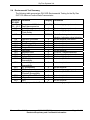
1
ISAT-100 Specifiations, Operating Instructions
and Install Manual
ISAT-100-OPD-SOI
Applies to: ISAT-100 Mod A
Document Revision: 01.048
September 08, 2006
SkyTrac Systems Ltd.
200-170 Rutland Rd N.
Kelowna, BC
Canada V1X 3B2
Tel. (250) 765-2393
Fax (250) 765-3767
Web: www.skytrac.ca
Email: [email protected]
Copyright © 2005 SkyTrac Systems Ltd.
All rights reserved.
Page 1 of 31
SkyTrac Systems Ltd.
Proprietary Notice: The Information contained in this document is proprietary and
confidential to SkyTrac Systems Ltd.
Document Revision History
Rev
ECO Page
01.20
-
Description
Initial Release
Date
July 2003
Approval
KWallace
01.30 012
Amendment to Install Notes:
Added upright mounting
requirement and vent hole
requirements.
Amendment to Install Notes:
Added paragraph on potential
Hydrogen release rate, suggested
install space and ventilation
requirements.
Amendment to Environmental
Test Summary: Section 9 and 22
Comments: Note 1.
Amendment to Continued
Airworthiness: Periodic
inspection notes
Amendment to Overview: Added
point 9 regarding PDA usage.
Amendment to Operating
Temperature
Amendment to EMI Test to be
consistent with EMI/RFI Test for
ISAT-100 (Doc # 238-50064-00)
Amendment to DO-160D:
Corrected DO-160D Category
Amendment to Operating
Temperature
DO-160D: Section 4.5 Add
Category A4
Revised second line to read
“Equipment near active
INMARSAT terminals”
Sept 18, 2003
KWallace
Oct 14, 2003
KWallace
Oct 16, 2003
KWallace
Oct 16, 2003
KWallace
Nov 7, 2003
KWallace
Nov 18, 2003
KWallace
Nov 18, 2003
KWallace
Nov 18, 2003
KWallace
Nov 20, 2003
KWallace
Nov 20, 2003
KWallace
Mar 3, 2004
KWallace
S 4.6
-
S 4.6
-
S 2.7
-
S 2.8
-
S 4.5
-
S 2.1
-
S 4.8.2
-
S 1.2
-
S 2.1
-
S 2.7
-
S 4, A-B
Pg 26
Document Rev. 01.048
ISAT-100-OPD-SOI
Restricted Proprietary and Confidential Information
Page 2 of 31
SkyTrac Systems Ltd.
Document Revision History Continued
Rev
ECO Page
S 1.4, Pg
6, S 2.3,
2.4, Pg 7,
S 4.5, Pg
10, S 4.7,
Pg 18
Fig 4-2,
Appendix
A REAR
Pg 8 *
01.40 019
-
S 4.6.1,
Pg 14
Table 4.1,
Pg 16
S 4.6.1
Fig 4.3
S 4.8
Fig 4.5
S 4.6
Fig 4-2,
S 4.6.1
Fig 4-4,
Table 4-2
01.41
01.42
01.43
022
026
01.44
-
Pg 1. Pg
6, Pg 14,
Pg 8,
01.45
-
P12
01.46
-
Pg 13
01.47
027
All
Description
Change discussion from two
separate antennae to one
combination antenna
Date
Apr 13, 2004
Approval
KWallace
Both modified to illustrate
connecting to one combination
antenna
* FAA Policy # 2001-01
Separate FADEC not required
Amendment to Data Connector
Diagram and Pin Description
Specified Pin J as Mission Switch
Apr 13, 2004
KWallace
June 1, 2004
KWallace
Aug 19, 2004
KWallace
Aug 19, 2004
KWallace
Dec 16, 2004
KWallace
Jan 5, 2005
KWallace
Updated Connector Diagram
according to Table 4.1
Updated Connector Pinout
Updated 10-Pin Connector Pinout & Jan 20, 2005
Description Table
KWallace
Updated Document Formatting
ISAT Rev 01.80 Release
Added instructions for identifying
the ISAT hardware version..
Added GPS not for navigational
purposes notice.
Remove reference to non existing
section.
Added installation requirement that
system connectors must be
connected before system power is
applied. Added instructions for
determining which Mod the ISAT is.
Updated SOI format implemented
Additional details on Maintenance
and Continued Airworthiness, and
Airworthiness Limitations were
added.
Feb 1, 2005
Feb 15, 2005
Apr 27, 2005
KWallace
G. Pringle
G.Pringle
May 30, 2005
K.Wallace
Document Rev. 01.048
ISAT-100-OPD-SOI
Restricted Proprietary and Confidential Information
Page 3 of 31
SkyTrac Systems Ltd.
Document Revision History Continued
Rev
ECO
01.048 088
Page
1, 5
Description
Updated Address
Date
Sept-08-06
Document Rev. 01.048
ISAT-100-OPD-SOI
Restricted Proprietary and Confidential Information
Approval
T.Ratch
Page 4 of 31
SkyTrac Systems Ltd.
Warning
Changes or modifications not expressly approved by SkyTrac Systems Ltd. could void the
user’s authority to operate the equipment.
Warranty Information
SkyTrac Systems Ltd (STS) warrants this product to be free of defects in materials and
workmanship, and that the product meets or exceeds approved factory acceptance test
requirements. STS reserves the right to replace any warranted product at its sole discretion
during the warranty period.
The Model ISAT-100 Airborne Data/Position Communicator is under warranty for one year
from date of purchase. Failed units caused by defective parts, or workmanship should be
returned to:
SkyTrac Systems Ltd.
200-170 Rutland Rd. N
Kelowna, B.C. Canada
V1X 3B2
Document Rev. 01.048
ISAT-100-OPD-SOI
Restricted Proprietary and Confidential Information
Page 5 of 31
SkyTrac Systems Ltd.
Table Of Contents
1
GENERAL .....................................................................................................................................8
1.1
1.2
1.3
1.4
2
INTRODUCTION ........................................................................................................................8
DESCRIPTION ..........................................................................................................................8
PURPOSE OF EQUIPMENT .......................................................................................................8
SYSTEM REQUIREMENTS ........................................................................................................9
SPECIFICATIONS .....................................................................................................................10
2.1
PHYSICAL PROPERTIES ........................................................................................................10
2.2
TECHICAL SPECIFICATIONS...................................................................................................10
2.2.1
GPS Receiver .............................................................................................................10
2.2.2
ISAT-100 Combination Antenna ..............................................................................10
2.2.3
Satellite Transceiver ..................................................................................................11
2.3
EMISSIONS COMPLIANCE ......................................................................................................11
2.4
ENVIRONMENTAL TEST SUMMARY........................................................................................12
3
AIRWORTHINESS LIMITATIONS..........................................................................................13
3.1
3.2
4
INSTALLATION LIMITATIONS...................................................................................................13
OPERATION LIMITATIONS ......................................................................................................13
INSTALLATION INSTRUCTIONS ..........................................................................................14
4.1
INSTALLATION REQUIREMENTS .............................................................................................14
4.2
UNPACKING AND INSPECTING ...............................................................................................14
4.2.1
Identifying Your ISAT.................................................................................................14
4.2.2
Equipment Packing Log ............................................................................................14
4.2.3
Installation Kit - Contents ..........................................................................................14
4.3
OVERVIEW .............................................................................................................................15
4.4
ISAT-100 INSTALLATION ......................................................................................................15
4.4.1
Pin Locations and Connections ...............................................................................17
4.5
ANTENNA INSTALLATION .......................................................................................................23
4.6
PROGRAMMING PORT ...........................................................................................................24
4.7
POST INSTALLATION TESTS ..................................................................................................25
4.7.1
Function Test ..............................................................................................................25
4.7.2
EMI Test.......................................................................................................................25
5
OPERATING INSTRUCTIONS................................................................................................27
5.1
5.2
6
OPERATING INSTRUCTIONS ..................................................................................................27
ACTIVATION ...........................................................................................................................27
MAINTENANCE AND CONTINUED AIRWORTHINESS ...................................................28
6.1
6.2
CONTINUED AIRWORTHINESS ...............................................................................................28
MAINTENANCE INSTRUCTIONS ..............................................................................................28
Document Rev. 01.048
ISAT-100-OPD-SOI
Restricted Proprietary and Confidential Information
Page 6 of 31
SkyTrac Systems Ltd.
7
APPENDIX A ..............................................................................................................................29
7.1
7.2
8
ISAT-100 FRONT PANEL DIAGRAM .....................................................................................29
ISAT-100 REAR PANEL DIAGRAM .......................................................................................30
APPENDIX B ..............................................................................................................................31
8.1
8.2
CAUSES OF RF INTERFERENCE ............................................................................................31
MITIGATION OF RF INTERFERENCE ......................................................................................31
Document Rev. 01.048
ISAT-100-OPD-SOI
Restricted Proprietary and Confidential Information
Page 7 of 31
SkyTrac Systems Ltd.
1
1.1
GENERAL
Introduction
This publication provides technical information for the ISAT-100 Position/Data
Communicator (Mod A), developed by SkyTrac Systems Ltd. The ISAT-100 will
provide position reporting and messaging with global coverage in near real time.
1.2
Description
The ISAT-100 contains a GPS (Global Positioning System) receiver, an L-Band
transceiver specifically designed to communicate with the Iridium® satellite system, a
battery which enables communications with the satellite system after airframe power
shutdown and a battery charging system. Control and interfacing is provided with a
low power single-board computer.
The ISAT-100 is compliant with RTCA DO-160D environmental category Cat.
[(A4)(D1)]XAB[(SMB)(UF)]XXXXXXZBBXXXHXXXX and carries an airworthiness
approval.
Appendix A illustrates the Front and Rear Panel layout of the ISAT-100.
1.3
Purpose of Equipment
The ISAT-100 is the primary hardware component of a system designed to provide
automatic message reporting, 2-way messaging and other data transfers between an
aircraft and any point in the world having Internet access, via the Iridium® Low Earth
Orbit (LEO) satellites. Present position and text messages from the aircraft can be
displayed on any computer with Internet access and SkyTrac software. Position
reporting intervals are user defined. Base software displays current and historical
position data including latitude, longitude, GPS time, relative position (to a known
way point), ground speed, altitude and heading, in tabular format and on a map.
Airtime, flight time, ETA, distance traveled, time elapsed and other flight data is also
displayed for instant viewing. Flight reports can also be generated by unit and time
frame (i.e. airtime/flight time per day/week/month).
Operationally, the ISAT system can compliment flight following requirements for
commercial operators and provide vital position data and messaging services to
those operators conducting flight activities in remote areas.
Document Rev. 01.048
ISAT-100-OPD-SOI
Restricted Proprietary and Confidential Information
Page 8 of 31
SkyTrac Systems Ltd.
1.4
System Requirements
1.5
The ISAT system must receive GPS signals to enable the determination of its present
position and communicate (send/transmit) with the Iridium® LEO satellite system.
A Windows-based PC and a dedicated email address are required at the Base
Location.
Minimum Operating System Requirements for SkyTrac Base Software
Windows 2000® OS
Pentium Type Processor – 500 MHz
64 Megabytes of RAM
350 Megabytes of Hard Disk Space
Email connection with POP3 and SMTP
CD-ROM drive
− Video Card capable of High Colour (16-bit) display
Display setting must be set to High Colour (16-bit) or better. This setting can be found
in Start ► Settings ► Control Panel ► Display Settings, or right-click on your
desktop select Properties ► Settings Tab.
−
−
−
−
−
−
Document Rev. 01.048
ISAT-100-OPD-SOI
Restricted Proprietary and Confidential Information
Page 9 of 31
SkyTrac Systems Ltd.
2
2.1
SPECIFICATIONS
Physical Properties
Operating Temperature
Size
Weight
Power Requirement
Mounting
2.2
-15ºC to +55ºC (RTCA DO-160D)
-40ºC to +65ºC (manufacture test)
10” (L) excluding connectors, 3.5” (H)
4.2” (W) plus 1.5 “ bottom mounting flange
2.3 kg (5.07 lbs)
Nominal standard 28VDC system bus via 3 Amp breaker.
*Actual consumption is 0.5 Amp typical, 1.5 Amp while
transmitting. Equipped with reverse voltage and transient
protection.
6 x 3AN bolts, flange mount horizontally with mounting
brackets on the bottom.
Normal air circulation required: Do not cover vent holes
in top cover or in sides (2) of unit.
Techical Specifications
2.2.1 GPS Receiver
Receiving Method
Acquisition time
Position accuracy
Acceleration
12 Channel, Parallel Receiver
48 seconds after power up (cold start)
0.1 seconds for re-acquisition.
Less than 25 m without Differential GPS
1-5m with Differential GPS - WAAS enabled
4 G max
2.2.2 ISAT-100 Combination Antenna
Active L1 GPS/Passive Iridium Antenna, low profile, moulded radome.
Height:
0.721 in. (18.31 mm)
Length:
5.026 in. (127.66 mm)
Width:
2.0 in. (55.88 mm)
Weight:
8.0 oz (226 g)
Voltage:
3.0 to 28.0 VDC @ 50 mA max
Gain (GPS antenna): 32dB min
The Iridium® satellite serving a Short Burst Data call can literally be anywhere in orbit
at a given moment in time. For this reason, it is imperative that the antenna be
mounted outside, as high as possible, in a horizontal position on the aircraft,
attempting to achieve a 360-degree view of the sky with minimal obstructions.
Document Rev. 01.048
ISAT-100-OPD-SOI
Restricted Proprietary and Confidential Information
Page 10 of 31
SkyTrac Systems Ltd.
2.2.3 Satellite Transceiver
Operating frequency
*Power consumption
1616 MHz to 1626.5 MHz
Transmit (max) 7W
*The ISAT-100 is not classified as “Equipment known to have a high potential for interference” in accordance with FAA
Policy No.: ASW-2001-01 dated April 25, 2002. Separate FADEC testing is not required for this installation.
2.3
Emissions Compliance
Entity
US FCC
US FCC
ETSI
Document Title
Title 47 Code of Federal Regulations
Title 47 Code of Federal Regulations 1997
Satellite Earth Stations and Systems (SES);
Harmonized EN for
Document Number
Section 15.109
Section 25.202
EN 301 441
Document Rev. 01.048
ISAT-100-OPD-SOI
Restricted Proprietary and Confidential Information
Page 11 of 31
SkyTrac Systems Ltd.
2.4
Environmental Test Summary
The following table summarizes DO-160D Environmental Testing for the SkyTrac
ISAT-100 Airborne Position/Data Communicator.
Section of
DO-160D
4.5
4.6, 4.6.2
6.0
7.0
8.0
9.0
10.0
11.0
12.0
13.0
14.0
15.0
16.0
17.0
18.0
Condition
Temperature & Altitude
Rapid decompression
Humidity
Operational Shock and
Crash Safety
Vibration 1)
Category Comments
[A4, D1]
Meets category requirements
A
B
Meets category requirements
Meets category requirements
SMB/UF
Meets fixed wing standard
vibration, helicopter robust vibration
No test required. See Note 1.
No test required
No test required
No test required
No test required
No test required
<0.3m for 1 degree deflection
Meets category requirements
Meets category requirements
No test required
Explosion Proofness
X
Waterproofness
X
Fluid Susceptibility
X
Sand and Dust
X
Fungus Resistance
X
Salt Spray
X
Magnetic Effect
Z
Power Input
B
Voltage Spike
B
AF Conducted
X
Susceptibility
19.0
Induced Signal
X
No test required
Susceptibility
20.0
RF Susceptibility
X
No test required
21.0
RF Emissions
H
Meets category requirements
22.0
Lightning Induced
X
No test required. See Note 1.
Transient Susceptibility
23.0
Lightning Direct Effects
X
No test required
24.0
Icing
X
No test required
25.0
ESD
X
No test required
Note 1: Analysis provided to Transport Canada meets category requirements.
Document Rev. 01.048
ISAT-100-OPD-SOI
Restricted Proprietary and Confidential Information
Page 12 of 31
SkyTrac Systems Ltd.
3
3.1
AIRWORTHINESS LIMITATIONS
Installation Limitations
The following installation regulations must be adhered to:
• The ISAT-100 must be installed with the attached mounting brackets on the bottom to
insure proper ventilation of the ISAT unit (see section 2.1 for details).
• The ISAT-100 must be installed in a location that provided adequate ventilation
space, as specified in section 4.4.
3.2
Operation Limitations
GPS Information provided by ISAT not intended for navigational purposes.
Document Rev. 01.048
ISAT-100-OPD-SOI
Restricted Proprietary and Confidential Information
Page 13 of 31
SkyTrac Systems Ltd.
4
INSTALLATION INSTRUCTIONS
IMPORTANT NOTICE: All system interconnect cables must be connected
before power is applied to the system.
4.1
Installation Requirements
When installing the ISAT-100 the installer must have a working knowledge of aircraft
electronics installation, and be a holder of either an FAA Repairman’s Certificate or a
Transport Canada equivalent. All installations should meet the requirements of FAA
advisory circular AC43.13-1B.
4.2
Unpacking and Inspecting
4.2.1 Identifying Your ISAT
If the ISAT has a Mod A Label, then this installation manual applies to the ISAT. If the
ISAT does not have a MOD A label, please use the version of this manual appropriate
for your ISAT.
4.2.2 Equipment Packing Log
Save the original shipping container in case of need for return due to damage or
warranty claims. Check that each item listed on the packing slip has been shipped in
the container. Verify and record the IMEI Number of the ISAT-100. This information is
required when contacting SkyTrac Systems to activate the satellite communications
services.
4.2.3 Installation Kit - Contents
The ISAT-100 Installation Kit (P/N 010000-2) consists of the following:
ISAT Installation Kit (P/N 010000-2) Parts List
2
2
1
1
SMA Male Connector (crimp type) for RG-400 or equivalent low-loss coaxial
cable with 0.200” O.D.
TNC Male Connectors (crimp type) for RG-400 or equivalent low-loss coaxial
cable with 0.200” O.D.
Circular MS Bayonet Lock Connector, Straight Plug with Strain Relief
(MIL-C-26482, Series 1), such as
Amphenol MS3126F12-10S or
Souriau 851-06RC12-10S50
Circular MS Bayonet Lock Connector, Straight Plug with Strain Relief
(MIL-C-26482, Series 1), such as
Amphenol MS3126F14-19S or
Souriau 851-06RC14-19S50
Document Rev. 01.048
ISAT-100-OPD-SOI
Restricted Proprietary and Confidential Information
Page 14 of 31
SkyTrac Systems Ltd.
4.3
Overview
The main tasks for this installation are listed below:
1. Check the contents of the installation kit (P/N 010000-2) against those listed in
Section 4.4 of this manual.
2. Determine the approximate location of the ISAT-100, combination GPS/Passive
Iridium antenna.
Note:
Factors to be considered to determine install location include
maximum antenna coax lengths and minimum distance between
existing GPS and ISAT-100 combination antenna.
If ISAT-100 is to be installed near an active INMARSAT terminal
or if the aircraft that the ISAT-100 is installed in operates near an
active INMARSAT terminal please see Appendix B.
3. Mount the ISAT-100.
4. Mount the ISAT-100 combination antenna.
5. Route the coax cables for Iridium and GPS antenna signals to the ISAT-100
combination antenna.
6. Create the wire harness for the ISAT-100.
7. Check the data port using a PDA loaded with ITrax software, as per ITrax user
manual (P/N MAN-TRAX-001).
8. If a PDA is used:
• Make sure it has a serial connector
• RS 232 cable should not exceed 40 ft.
o Must use shielded RS 232 cable
4.4
ISAT-100 Installation
The ISAT-100 is designed to be secured by its mounting rails to the airframe using six
(6) AN-3 bolts and should be installed using the ISAT installation kit (P/N KIT-ISAT100). Figure 4-1: ISAT-100 Mounting Rails illustrates the locations for mounting
screws in the mounting rails on the sides of the ISAT-100.
It is important to achieve a good electrical bond between the ISAT-100 enclosure
and the airframe. Remove paint if necessary and prepare the mounting holes.
Document Rev. 01.048
ISAT-100-OPD-SOI
Restricted Proprietary and Confidential Information
Page 15 of 31
SkyTrac Systems Ltd.
FIGURE 4-1
ISAT-100 Mounting Rails
Important Note:
The ISAT-100 contains a sealed lead-acid battery as a backup power source. Under
extreme fault conditions, this device may release Hydrogen gas at a rate of up to
0.84 in3 per minute. The installer must install this device in an area with sufficient
ventilation and comply with FAR 29.1353 (c) for the final installation design.
The ISAT-100 must be mounted in an upright position and none of the venting holes
in the top cover or in either side panel should be covered at any time.
The free air volume around the ISAT-100 installation must be at least 8 cubic feet.
Like any other transmitter, the ISAT-100 should be installed as far from aircraft
apertures (such as windows) and as far from radio receiver antennae as practical.
Figure 4.2 illustrates the Block Diagram for the ISAT-100.
Document Rev. 01.048
ISAT-100-OPD-SOI
Restricted Proprietary and Confidential Information
Page 16 of 31
SkyTrac Systems Ltd.
FIGURE 4-2
ISAT-100 Block Diagram
4.4.1 Pin Locations and Connections
The identification letters and descriptions for the 19-pin System Connector and 10-pin
Data Connector, located on the front of the ISAT-100, are listed in Tables 4-1 and 4.2
and illustrated in Figures 4-3 and 4.4 respectively.
Both Pin B and Pin C on the System connector must be grounded in order to
enable the internal battery.
Use AWG 20 wire to hook up the 28VDC aircraft main power source protected
through a 3 Amp breaker to the ISAT-100. It is important to remember that the ISAT100 will sense the onrush of 28VDC and will send this event, together with a
timestamp, to the dispatch centre in order to signal the beginning of a flight. Thus, the
ISAT-100 should receive mains power as soon as the aircraft’s master or avionics
switch is turned on. The remaining Pins on J1 are reserved for future firmware
implementations.
Document Rev. 01.048
ISAT-100-OPD-SOI
Restricted Proprietary and Confidential Information
Page 17 of 31
SkyTrac Systems Ltd.
FIGURE 4-3
System Connector Diagram
Document Rev. 01.048
ISAT-100-OPD-SOI
Restricted Proprietary and Confidential Information
Page 18 of 31
SkyTrac Systems Ltd.
Table 4-1
System Connector - Pin Description
19 Pin System Connector
Pin #
Description
A
+28 VDC Main Power In
B
Ground (Power)
C
Battery Disconnect
D
Analog Input #1 0-30VDC
E
Analog Input #2 0-30VDC
F
Analog Input #3 0-30VDC
G
Analog Input #4 0-30VDC
H
Analog Input #5 0-30VDC
J
Voltage Seeking - Digital Input #1 (Mission Switch)
K
Voltage Seeking - Digital Input #2
L
Ground Seeking - Digital Input #3
M
Voltage Seeking - Digital Input #4
N
Ground Seeking - Digital Input #5 (Squat Switch)
P
Voltage Seeking - Digital Input #6 (Engine On/Off)
R
Ground Seeking - Digital Input #7 (Emergency)
S
Current Sinking Digital Output #1
T
Current Sinking Digital Output #2
U
Current Sinking Digital Output #3
V
Differential GPS Input
The above digital inputs on Pin N, P & R are set as factory default. Contact SkyTrac if
different configuration is required.
Document Rev. 01.048
ISAT-100-OPD-SOI
Restricted Proprietary and Confidential Information
Page 19 of 31
SkyTrac Systems Ltd.
System Connector –Pin Descriptions (Detailed)
Pin A +28 VDC Main Power In
This is the main power supply to the ISAT-100. The operating range is 18 - 30VDC
Pin B - Ground (Power)
This is the power ground connection for the ISAT-100.
Pin C - Battery Disconnect
Connect pin C to pin B or ground to enable the ISAT-100’s internal battery. This
feature allows the ISAT-100 with the connector removed to be placed in storage for
several months without completely draining the internal battery, which could
otherwise result in damage.
Pin D - Analog Input #1
An analog voltage level between 0 and +30 volts, when applied to pin D, will be
converted to a digital value with 12 bits of resolution.
Pin E - Analog Input #2
An analog voltage level between 0 and +30 volts, when applied to pin E, will be
converted to a digital value with 12 bits of resolution.
Pin F - Analog Input #3
An analog voltage level between 0 and +30 volts, when applied to pin F, will be
converted to a digital value with 12 bits of resolution.
Pin G - Analog Input #4
An analog voltage level between 0 and +30 volts, when applied to pin G, will be
converted to a digital value with 12 bits of resolution.
Pin H - Analog Input #5
An analog voltage level between 0 and +30 volts, when applied to pin H, will be
converted to a digital value with 12 bits of resolution.
Pin J - Digital Input #1 – Voltage Seeking - (Mission)
A positive input between 5V and 28V, when applied to pin J, will produce a digital
logic high.
Pin K - Digital Input #2 - Voltage Seeking
A positive input between 5V and 28V, when applied to pin K, will produce a digital
logic high.
Pin L - Digital Input #3 - Ground Seeking
A ground input when applied to pin L, will produce a digital logic high.
Document Rev. 01.048
ISAT-100-OPD-SOI
Restricted Proprietary and Confidential Information
Page 20 of 31
SkyTrac Systems Ltd.
Pin M - Digital Input #4 - Voltage Seeking
A positive input between 5V and 28V, when applied to pin M, will produce a digital
logic high.
Pin N - Digital Input #5 -Ground Seeking (Squat switch)
Grounding pin N will produce a digital logic high. The default configuration uses pin
N to monitor the aircraft’s squat switch.
Pin P - Digital Input #6 - Voltage Seeking (Engine on/off)
A positive input between 5V and 28V, when applied to pin P, will produce a digital
logic high. The default configuration uses pin P to monitor the aircraft’s engine
(on/off).
Pin R - Digital Input #7 - Ground Seeking (Emergency)
Grounding pin R will produce a digital logic high. The default configuration uses pin R
to monitor an emergency or panic switch.
Pin S- Digital Output #1 –Current Sinking
The default use for Digital output #1 is to indicate a message in the pilot’s inbox. This
output has been configured as a sinking output and can sink up to 200mA at 30VDC.
Pin T - Digital Output #2 –Current Sinking
The default use for Digital output #2 is to indicate an overdue position report. This
output has been configured as a sinking output and can sink up to 200mA at 30VDC.
Pin U – Digital Output #3 - Current Sinking
Pin S is a sinking digital output. This output has been configured to sink up to 200mA
at 30VDC.
Pin V - Differential GPS Input
Pin V is an RS-232 Differential GPS (DGPS) input.
Use shielded AWG 22, or smaller, cable to make up a serial cable for a PDA or
computer connection. Use pin A, B, and C for default set-up. Connect pin B to pin 2
and pin C to pin 3 on a male DB 9 connector for a PDA device. Switch pin 2 and pin 3
for a female DB9 computer connection. The remaining pins on J2 are reserved for
special firmware implementation.
Document Rev. 01.048
ISAT-100-OPD-SOI
Restricted Proprietary and Confidential Information
Page 21 of 31
SkyTrac Systems Ltd.
Figure 4-4
Data Connector Diagram
Table 4-2
Data Connector Pin Description
10 Pin Data Connector
Pin #
A
Description
D
E
F
G
H
J
Ground (Signal)
RS-232 Channel #1 – Transmit (use this channel to
connect PDA)
RS-232 Channel #1 – Receive (use this channel to
connect PDA)
RS-232 Channel #2 - Transmit
RS-232 Channel #2 - Receive
RS-485 Channel #1 - Negative
RS-485 Channel #1 - Positive
Voice Ground
Voice Speaker
K
Voice Microphone
B
C
Document Rev. 01.048
ISAT-100-OPD-SOI
Restricted Proprietary and Confidential Information
Page 22 of 31
SkyTrac Systems Ltd.
4.5
Antenna Installation
Active L1 GPS Passive Iridium Antenna (P/N: STS-ISAT-ANT)
The standard ISAT-100 installation will use a combination, active L1 GPS/Passive
low profile, molded radome, Iridium antenna (P/N: STS-ISAT-ANT). This
recommended system antenna is only available directly from SkyTrac Systems Ltd.
Please contact SkyTrac Systems to discuss the feasibility of using alternate antenna,
if required.
The combination antenna must be installed at least three feet away from any
other GPS antenna. It is imperative that the antenna be mounted outside, as high as
possible and in a horizontal position on the aircraft, attempting to achieve a 360degree view of the sky with minimal obstructions.
IMPORTANT NOTE: This antenna uses SMA connectors for the GPS jack and
TNC connectors for the L-Band or Iridium jack. Immediate damage will occur to
the ISAT-100 if either cable is connected to the wrong jack.
The use of RG-400 low-loss coaxial cable restricts the maximum length of the cable
to 18 ft. If a longer run is required, use lower loss coax cable like ECS 310801,
311601, 311501, 311201 and refer to manufacturers specs for attenuation at 1.6
GHz. Attenuation of equal or less than 3dB is required. The bond between the
airframe and the antenna needs to be 10 milliohms or less.
Prepare the mounting location by drilling holes in the aircraft skin or through a
mounting plate. Use a doubler plate of 4 x 6 inches if antenna is installed on a nonmetallic aircraft surface to create a ground plane. The plate must have an electrical
connection to the antenna ground.
Installation of an antenna on the aircraft should be performed only as defined by the
aircraft manufacturer or in accordance with TC or FAA approved engineering data.
Special caution must be observed when installing antennae in pressurized aircraft.
Note: The ISAT combination antenna includes a rubber seal that must be
properly installed into the groove on the underside of the antenna prior to
mounting the antenna. This seal acts as an environmental seal from the
outside atmosphere. Any connections that are not protected from the outside
atmosphere by the rubber antenna seal should have an environmental seal
applied to them during installation.
Document Rev. 01.048
ISAT-100-OPD-SOI
Restricted Proprietary and Confidential Information
Page 23 of 31
SkyTrac Systems Ltd.
4.6
Programming Port
The programming port (Figure 4-5) is used to install new or revised firmware in the
ISAT-100. SkyTrac Systems will issue a PC executable file that will perform any
upgrade. A standard serial DB9 computer cable (RS-232) will be required to connect
a laptop or PC to the ISAT-100.
Figure 4-5
Programming Port (Rear Panel)
Document Rev. 01.048
ISAT-100-OPD-SOI
Restricted Proprietary and Confidential Information
Page 24 of 31
SkyTrac Systems Ltd.
4.7
Post Installation Tests
4.7.1 Function Test
The avionics installer must perform this test immediately after installation.
a) Move aircraft to a location with unrestricted visibility of the sky.
b) Turn on aircraft master/avionics switch. Power and Charge LED should light up
immediately followed by the BAT, MDM and GPS LED. Note that it may take up to
2 minutes for the GPS LED to light up, as the GPS has to lock on to at least 2
satellites.
c) Connect the PDA with SkyTrac ITrax software to the ISAT-100 Data Port using
the Data Cable. In the ITrax software verify communication with the PDA and
verify valid GPS time displayed on the PDA. For more information, please refer to
ITrax user manual (P/N MAN-TRAX-001)
Turn master/ avionics switch off. Power and Charge LED should turn off immediately.
Wait for up to 3 minutes, the BAT, MDM and GPS LED should turn off as the unit
goes into sleep mode. Contact dispatch to verify receipt of data. If dispatch is not
available or base software has not been set up, contact SkyTrac Systems.
4.7.2 EMI Test
(See Document EMI/RFI Tests for ISAT-100 (Document #238-50064-00))
The purpose of this test report is to verify that the operation of the ISAT-100 does not
interfere with basic aircraft systems and avionics. The ISAT-100 and PDA should be
installed and function tested.
The L-Band antenna (TNC connector) VSWR should be checked. A forward/reverse
power check with an in-line wattmeter should show no more than 10% reflected
power.
Most of the EMI tests can be accomplished on the ground. In some cases flighttesting is required or is easier. If the aircraft is approved for IFR operations, then it is
mandatory that interference between the ISAT-100 and the approach aids be
checked in-flight.
The existing on-board GPS should be operational and navigating with at least the
minimum compliment of satellites. The VHF Comm should be set to commonly used
frequencies with the squelch open. VOR/DME receivers should be selected for
display. If possible, set up a DME ramp test set on the frequencies indicated and
adjust the output until the flags are out of view. The transponder and encoder should
be monitored with ramp test equipment. Set the output of the transponder test set to
3db above the output necessary to achieve 90% reply. If possible set the ADF to a
nearby navigation station.
Document Rev. 01.048
ISAT-100-OPD-SOI
Restricted Proprietary and Confidential Information
Page 25 of 31
SkyTrac Systems Ltd.
Operate the ISAT-100 unit for at least 10 minutes in default mode (i.e. factory set to
transmit to the satellite system every one minute). This will provide 10 transmissions
during the test procedure. DO NOT CHANGE THE DEFAULT TRANSMISSION
INTERVAL UNITL AFTER ALL POST INSTALLATION TESTS ARE COMPLETED.
Observe the GPS for any degradation in satellite status, availability or flags. Listen for
any noise or detected audio signals on the VHF Comm(s). Listen for any noise or
detected audio signals on the VOR/LOC receiver audio; look for any movement of
flags or needles on the VOR/LOC/GS navigation display(s). Observe the transponder
for any loss of reply or spurious reply.
List the power plant, fuel and other electric instruments on the EMI/RFI Test Report
(Document #238-50064-00) and note any anomalies that occur while transmitting.
Assess the results.
If the aircraft is equipped with an autopilot or a stability augmentation system, then
test fly the aircraft and verify that operation of the ISAT-100 unit does not have
adverse effects on these systems. After checking for gross effects at a safe altitude,
fly an approach with each of the different navigation systems coupled to the autopilot
(ILS, GPS ETC.) and look for any anomalies.
If the installed system passes all of the applicable EMI tests, then no further action is
required. If interference is observed then the interference must be assessed against
the appropriate standards of airworthiness for the system in question. For example it
is permissible for a VFR certified GPS to lose navigation capability while the ISAT100 unit is transmitting, providing that it recovers properly and promptly, but it is not
permissible for an IFR Approach certified GPS to be affected in the same way. A
complete discussion of all the standards of airworthiness to be applied in assessing
EMI effects is beyond the scope of this document.
Document Rev. 01.048
ISAT-100-OPD-SOI
Restricted Proprietary and Confidential Information
Page 26 of 31
SkyTrac Systems Ltd.
5
5.1
OPERATING INSTRUCTIONS
Operating Instructions
There are no specific instructions for operation of the ISAT-100 in the airframe once it
has been correctly installed and activated by SkyTrac Systems. The LED function
and status lights indicate normal ISAT-100 operation. All LED lights should be on
steady if the ISAT is working properly and the ISAT has strong Iridium satellite link
and GPS lock. The position-reporting function of the ISAT-100 is transparent to the
aircraft crew. The position-reporting interval can be set using a portable PDA (using
Palm OS 3.5 and SkyTrac software). Text messages may be accessed or sent (i.e.
to/from the aircraft) also using a portable PDA prior to and after a flight. The SkyTrac
PDA software for the Palm OS 3.5 is called “ITrax” and can be downloaded from the
SkyTrac website.
5.2
Activation
To establish your communications contract and/or activate your ISAT-100 unit(s)
please contact customer service at:
SkyTrac Systems Ltd.
200-170 Rutland Rd N.
Kelowna, BC Canada
V1X 3B2
Ph: 250 492-5363
Fax: 250 487-7607
www.skytrac.ca
Please check the SkyTrac web site to confirm that your software is the latest version.
Please allow two business days to activate your units on the Iridium® Satellite
Network.
Document Rev. 01.048
ISAT-100-OPD-SOI
Restricted Proprietary and Confidential Information
Page 27 of 31
SkyTrac Systems Ltd.
6
6.1
MAINTENANCE AND CONTINUED AIRWORTHINESS
Continued Airworthiness
The ISAT-100 does not require any maintenance if installed in an actively flying
aircraft, other than the battery replacement as per note below.
NOTE:
All batteries are subject to service life restrictions. The built-in sealed
lead-acid battery must be replaced by SkyTrac Systems after a service
life of five (5) years.
If the ISAT-100 is not installed in an actively flying aircraft for a period of
time that is greater than 3 months, apply 28 Volts to System connector
for six (6) hours to maintain battery charge.
Periodic inspection is required as follows:
• Operator is to inspect the Mains Power breaker once every six months
to verify proper operation of the breaker.
• Operator is to inspect the ISAT-100 LED’s once every six months to
verify proper operation of the ISAT-100 charging circuit.
6.2
Maintenance Instructions
With the exception of the backup lead-acid battery (see maintenance details in section 6.1
above), the ISAT-100 does not require any maintenance.
Document Rev. 01.048
ISAT-100-OPD-SOI
Restricted Proprietary and Confidential Information
Page 28 of 31
SkyTrac Systems Ltd.
7
7.1
APPENDIX A
ISAT-100 Front Panel Diagram
Document Rev. 01.048
ISAT-100-OPD-SOI
Restricted Proprietary and Confidential Information
Page 29 of 31
SkyTrac Systems Ltd.
7.2
ISAT-100 Rear Panel Diagram
REAR
Dimensions – inch (mm)
Document Rev. 01.048
ISAT-100-OPD-SOI
Restricted Proprietary and Confidential Information
Page 30 of 31
SkyTrac Systems Ltd.
8
8.1
APPENDIX B
Causes of RF Interference
Some subscribers have contacted Iridium® regarding the loss of signal quality when they
operate their equipment near active INMARSAT terminals.
The power with which INMARSAT units transmit can overpower the Iridium® unit’s ability to
properly maintain a quality connection with the Iridium® satellite constellation. INMARSAT
terminals are often found in the same locations as Iridium® subscribers’, generally airports
and harbors (especially aboard ships).
In relation to the Iridium® unit’s antenna, the location of the INMARSAT unit’s antenna plays
a significant role in determining the degree of signal degradation an Iridium® subscriber will
experience. All Iridium® units are susceptible to this interference, regardless of the type of
antenna being used.
Susceptibility to interference from an INMARSAT terminal applies to all Iridium® end-user
products (9500 and 9505 equipment, including the L-Band Transceiver (LBT), which is
contained in products developed by SkyTrac Systems). Generally speaking, an Iridium® unit
located within 15 to 45 meters (50 to 150 feet, respectively) of an operating INMARSAT
mini-M or Standard-C terminal, will likely experience interruption in the unit’s performance.
Other sources of RF interference such as Globalstar® units, radar devices and broadcast
stations can cause interference for Iridium® units, but usually are not encountered as
frequently as INMARSAT terminals.
8.2
Mitigation of RF Interference
Degradation of service due to RF interference to the Iridium® unit can be significantly
improved by performing either or both of the following actions: a) increasing the distance
and moving the Iridium® antenna off axis from the source of the interference, b) using an
external band pass filter and an external antenna.
In determining the optimal location for mounting an external Iridium® antenna in a location
where INMARSAT antennae are also located, be certain that the Iridium® antenna is
mounted either to the side or behind the INMARSAT antenna, as well as above or below it.
Also note that the length of the feed line (the cable running from the Iridium® unit to the
antenna) plays an important role in the performance of the unit.
Document Rev. 01.048
ISAT-100-OPD-SOI
Restricted Proprietary and Confidential Information
Page 31 of 31