1
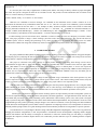
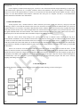
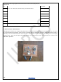
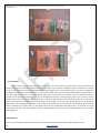
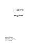
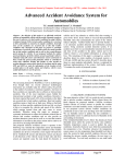
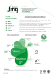
International Journal of Engineering Research and General Science Volume 3, Issue 3, May-June, 2015
ISSN 2091-2730
Accident Detection System using AT89C51 Microcontroller
K.N.Dongre, R.P.Kamdi, S.K.Tiwari, S.S.Roy, .Y.S.Kale,
Assistant Professor, Electronics & Telecommunication Engg. Dept. Yeshwantrao Chavan College of Engg. Nagpur,
[email protected] , #9665934468
Abstract- The Rapid growth of technology and infrastructure has made our lives more easy . The advent of technology has also
increased the traffic hazards and the road accident take place frequently which causes huge loss of life and property because of the
poor emergency facilities. Our project will provide an optimum solution to this draw back. According to this project when a vehicle
meets with an accident immediately Vibration sensor will detect the signal. Microcontroller sends the alert message through the GSM
MODEM including the location to police control room or a rescue team. So the police can immediately trace the location through the
key for location, after receiving the information. Then after conforming the location necessary action will be taken. If the person meets
with a small accident or if there is no serious threat to anyone`s life, then the alert message can be terminated by the driver by a switch
provided in order to avoid wasting the valuable time of the medical rescue team. This paper is useful in detecting the accident
precisely by means of both vibration sensor and smoke sensor. As there is a scope for improvement and as a future implementation we
can add a wireless webcam for capturing the images which will help in providing driver`s assistance.
Keywords - Accident Automatic Detection, GSM, smoke sensor, vibration sensor. Wireless webcam, MODEM
1. INTRODUCTION
There is a drastic increase in the number of vehicles in these days which also cause a steep rise in the number of accidents with
a lot of people losing their lives. According to the World Health Organization, an estimated 1.2 million people lose their lives every
year due to car accidents.India's road accident records 16 % of the world's road accident deaths, whereas India has only 1 % of the
world's road vehicles. It is due to the increase in the number of vehicles without a subsequent increase in the road facilities required
for it. In most of the accident cases, the victims
lose their lives because of the unavailability of medical facilities at the right time. To solve problems like these, this project came into
existence.
This project is mainly used to track the position of the Vehicle by the owner with the help of GSM technology and location
keys. In case of any accident, the system sends automated messages to the pre-programmed numbers. We can send messages to any
number of mobiles. The owner of the vehicle, Police to clear the traffic, Ambulance to save the people can be informed by this device.
This uses a location keys to know the exact position of the vehicle with an accuracy of a few feet. GSM is used to receive SMS from
the user and reply the position of the vehicle through a SMS.
.A 8051 microcontroller is used to control and co-ordinate all the parts used in this system. When there is any accident, the vibration
sensor gives the signal to the microcontroller, which sends the information to the LCD display through GSM network.
The automatic accident tracking system module uses an IR pair. The transmitter circuit transmit the IR waves towards the target
and in receiver section, receiver receive the IR signals with variations and give suitable output to the microprocessor. If there ia sn
occurance of fire during accident, the smoke detector will detect the smoke which in turn will activate the location keys to tract the
position of the vehicle to give a suitable input to the microcontroller. The microcontroller circuit processes the input and sends the
appropriate output according to the programming done
GSM Technology
GSM (Global System for Mobile Communications, originally Group Spécial Mobile), is a standard developed the European
Telecommunications Standards Institute (ETSI) to describe protocols for second generation (2G) digital cellular networks used by
mobile phones. The GSM Based System is one of the most important systems, which integrate GSM technologies.
925
www.ijergs.org
International Journal of Engineering Research and General Science Volume 3, Issue 3, May-June, 2015
ISSN 2091-2730
It is necessary due to the many of applications of GSM systems and the wide usage of them by millions of people throughout
the world. This system is designed to detect the car accidents on road that provides real-time information such as location of the
driver in a concise and easy-to-read format to
provide medical facility on occurrence of the accident.
GSM uses AT commands to send text messages. AT commands are the instructions used to control a modem. AT is the
abbreviation for Attention. Every command line starts with “AT” or “at” . There are two types of AT commands. [1] basic commands
are AT commands that do not start with a “+”. For example, D (dial), A(answer), H(hook control), and O(return to online data
state).[2] Extended commands are AT commands that start with a “+”. All GSM AT commands are extended commands. For
example, +CMGS (Send SMS Message), +CMGL (List SMS Messages) and +CMGR (Read SMS Messages). Contents of Text
sms are as follows:[1]Accident has occurred.[2]Longitude = 18 38.6878 N[3]Latitude = 73 45.3423 E.
A vehicle tracking system is an electronic device, installed in a vehicle to enable the owner or a third party to track the vehicle's
place. This paper proposed to design a vehicle tracking system that works using GSM technology. This system built based on
embedded system, used for tracking and positioning of any vehicle by using keys for location and Global system for mobile
communication (GSM). This design will continuously watch a moving Vehicle and report the status of the Vehicle on demand
2.
LITERATURE REVIEW
The papers published in IEEE journals regarding vehicle position tracking system and its implementation on Fpga has helped to
develop this project by analyzing the defects and using the effective ways from all resources available. The concept of the reference
papers and how it helped in designing this system is described in the following subsections.
This project is referenced to the paper ―Design of vehicle position tracking system using short message services and its
implementation on fpga‖ done by Arias Tanti Hapsari , Eniman Y Syamsudin and, Imron , Pramana. In this reference paper author
used ‗GPS module„ to receive the vehicular position and, ‗short messaging service via mobile phone„ to receive user request and
tosend the vehicle„s position. These components are controlled by a system which is designed using VHDL on Altera MAX plus I1
software, and it is implemented on FPGA chip Altera UPlX demoboard (Altera FLEX 10KEPF). In this way the author gets the
position of the vehicle and send it to any user who gives the request for tracking.
The objective of this project is to achieve a design of such system that can give information of the vehicle position every time
there's a request for it. Safety and security is a major concern for all vehicle owners . This vehicle tracking system ensures safety and
security of vehicle by tracking its position and sending it to owner or any people whenever it is requested by them.
And also GPS system ensures maximum accuracy in finding the vehicular position rangingwithin few feets. Using the mobile
phone attached in the system ,the position of the vehicle is sent as―short message service‖(SMS) to the requested people. The
designed system is implemented on Altera UPlX demohoard. There are two testing and verification procedures of this system.
Another paper referenced is‖ GPS-based Vehicle Tracking System-on-Chip‖. Modern powerful reconfigurable systems are
suited in the implementation of various data-stream, data parallel ,and other applications . An application that needs real-time, fast,
and reliable data processing is the global positioning system (GPS)-based vehicle tracking system (VTS). This system is designed
using a system-on-chip (SOC) replacement of the current microcontroller-based implementation. The proposed SOC is built on a field
programmable gate array (FPGA) promising a cheaper design, a more cohesive architecture, a faster processing time and an enhanced
system interaction .Reconfigurable systems enable extensive exploitation of computing resources. The reconfiguration of resources in
different parallel topologies allows for a good matching with the inherent intrinsic parallelism of an algorithm or a specific operation
The introduction of a new paradigm in hardware design called Reconfigurable Computing(RC) offers to solve any problem by
changing the hardware configurations to offer the performance of dedicated circuits. Reconfigurable computing enables mapping
software into hardware with the ability to reconfigure its connections to reflect the software being run. The ability to completely
reprogram the computer„s hardware implies that this new architecture provides immense scope for emulating different computer
architectures.
926
www.ijergs.org
International Journal of Engineering Research and General Science Volume 3, Issue 3, May-June, 2015
ISSN 2091-2730
As the complexity of FPGA-based designs grow, a need for a more efficient and flexible design methodology is required. One
of the modern tools is Quartus II. It is a compiler, simulator, analyzer and synthesizer with a great capability of verification and is
chosen to be used for this implementation. It consists of two main parts, the Base Station (BS) and the Mobile Unit (MU). The BS
consists of a PIC Microcontroller based hardware connected to the serial port of a computer. The MU is a self-contained PIC
Microcontroller based hardware and a GPS module.
3. PROPOSED METHOD
In this proposed work, a normal method of vehicle detection system used to track the vehicle by using keys and GSM
technology. If there is an accident the vibration sensor senses the vibration level and if it exceeds the threshold limit, the system will
consider that there is an occurrence of accident in that particular location. Then the system will activate the keys to gather the location
detail and sends the location of the vehicle through GSM to the control station.If any interruption occurs, then the IR sensor senses
the signals and SMS sends to the microcontroller. The controller issues the message about the place of the vehicle to the car owner or
authorized person. The microcontroller then sends suitable output to the GSM via MAX232.
When the vehicle detects abrupt change in the g-forces with the help of vibration sensor, which set the flag bit of
microcontroller 89c51RD2 as soon as accident is detected .We set the effective sensitive value for vibration sensor, in which accident
or crash can be detected .When microcontroller detects the accident or set bit through vibration sensor, it further give the display in
LCD that accident had occurred and indicate the accident through LED. Simultaneously Microcontroller activates the GSM module
[10], which have a manually saved phone number of police control room or family member of accident victim, sends a pre stored SMS
to that number .
If there is an occurrence of fire during the accident the system also consists of a smoke sensor to detect the smoke . A GSM
modem is interfaced with the microcontroller unit (MCU). The GSM modem sends an SMS to the predefined mobile number and
informs about the accident.ATS is built around the AT89C51RD2 microcontroller from Atmel. This microcontroller provides all the
functionality of the SMS system .It also takes care of filtering of the signals at the inputs. Only after an input remains unchanged for
30 milliseconds, is the new signal level is passed on for processing by the microcontroller program. This time can be varied by
adopting small change in the source code.
4. BLOCK DIAGRAM
The Block diagram of Automatic Vehicle detection system based on GSM technology is shown in the figure1.
927
www.ijergs.org
International Journal of Engineering Research and General Science Volume 3, Issue 3, May-June, 2015
ISSN 2091-2730
It consists the power supply section, keyboard, GSM, GPS, microcontroller, MAX232driver, relay driver, IR Transmitter, IR
receiver, LCD. The GSM board has a valid SIM card with a sufficient recharge amount to make outgoing calls. The circuits powered
by +5v Dc.
5. CIRCUIT DESCRIPTION
VIBRATION SENSOR:
In case of any accident, the vibration in vibration sensor increases the limit and information to the GSM module.
The GSM module can send message to respective authority. Thus this system ensures the life security.
In information sending module module GSM vibration sensor are used. In this, the system vibration sensor, GSM is placed in the
vehicle. If an accident occurred the vibration sensor senses the vibration level and if it exceeds the threshold limit the system will
consider that there is an occurrence of accident in that particular location.
MAX 232:
Signal coming from microcontroller is between 0 to 5v, but GSM requires signal in between -9 to 9v. so the conversion in the
amplitude is done by MAX 232. It is basically a level shifter .
POWER SUPPLY:
+5v power supply which is useful when experimenting with digital electronics, small inexpensive wall transformer with variable
output voltage.
features
•
Brief description of operation: Gives out well regulated +5V output, output current capability of 100 mA
•
Circuit protection: Built-in overheating protection shuts down output when regulator IC gets too hot
•
Circuit complexity: Very simple and easy to build
•
Circuit performance: Very stable +5V output voltage, reliable operation
•
Availability of components: Easy to get, uses only very common basic components
•
Design testing: Based on datasheet example circuit, I have used this circuit succesfully as part of many electronics projects
•
Applications: Part of electronics devices, small laboratory power supply
•
Power supply voltage: Unreglated DC 8-18V power supply
•
Power supply current: Needed output current + 5 mA
928
www.ijergs.org
International Journal of Engineering Research and General Science Volume 3, Issue 3, May-June, 2015
ISSN 2091-2730
•
Component costs: Few dollars for the electronics components + the input transformer cost
Description
This circuit is a small +5V power supply, which is useful when experimenting with digital electronics. Small inexpensive wall
tranformers with variable output voltage are available from any electronics shop and supermarket. Those transformers are easily
available, but usually their voltage regulation is very poor, which makes then not very usable for digital circuit experimenter unless a
better regulation can be achieved in some way. The following circuit is the answer to the problem.
This circuit can give +5V output at about 150 mA current, but it can be increased to 1 A when good cooling is added to 7805 regulator
chip. The circuit has over overload and terminal protection.
Pinout of the 7805 regulator IC.
•
1. Unregulated voltage in
•
2. Ground
•
3. Regulated voltage out
GSM MODEM:
GSM product provides full functional capability to serial devices to send sms. The product is available as broad level or enclosed in
metal box. The product has sim card holder to which 5V Regulated power supply activated sim card is inserted for normal use.it
provides great feasibility for devices in remote location to stay connected which otherwise would not have been possible where
telephone lines does not exist.
SMOKE DETECTOR:
Smoke detector is a circuit that used to detect any smoke in the particular range.Smoke detector circuits uses an IC 555 that is a timer
IC. This circuit uses very simple approach to detecting smoke in the air. It uses an (LDR) as a light detector.As fire comes across the
LDR range, the resistance of the LDR changes, which is turn trigger an alarm.
CONCEPT: LDR is enclosed in cylindrical case so it remains in dark and having a high resistance in normal condition. When smoke
enters in the case the LDR resistance decreases and hence desired output is obtained.
IC 555:
555 IC is an integrated circuit which is used in a variety of timer application. The 555 can be used to provide time delays.555 includes
25 transistor, 2 diodes and 15 resistor,on a silicon chip installed in an 8 pin mini dual in line package.It uses an IR pair. The
transmitter circuit transmit the IR waves and in receiver section receive the IR signals with variations & give suitable output to
microcontroller.IR photoreceiver is a two terminal PN junction device which operates in a reverse bias . It has a small transparent
window which allows light to strike the PN junction.
AT89C51:
929
www.ijergs.org
International Journal of Engineering Research and General Science Volume 3, Issue 3, May-June, 2015
ISSN 2091-2730
AT89C51 is an 8-bit microcontroller and belongs to Atmel's 8051 family. ATMEL 89C51 has 4KB of Flash programmable and
erasable read only memory (PEROM) and 128 bytes of RAM. It can be erased and program to a maximum of 1000 times.
In 40 pin AT89C51, there are four ports designated as P1, P2, P3 and P0. All these ports are 8-bit bi-directional ports, i.e., they can be
used as both input and output ports. Except P0 which needs external pull-ups, rest of the ports have internal pull-ups. When 1s are
written to these port pins, they are pulled high by the internal pull-ups and can be used as inputs. These ports are also bit addressable
and so their bits can also be accessed individually.
Port P0 and P2 are also used to provide low byte and high byte addresses, respectively, when connected to an external memory. Port 3
has multiplexed pins for special functions like serial communication, hardware interrupts, timer inputs and read/write operation from
external memory. AT89C51 has an inbuilt UART for serial communication. It can be programmed to operate at different baud rates.
Including two timers & hardware interrupts, it has a total of six interrupts.
Pin Diagram:
AT89C51 Microcontroller Pin Diagram, PinouT
Pin No
Function
Name
1
P1.0
2
P1.1
3
P1.2
4
8 bit input/output port (P1) pins
P1.3
5
P1.4
6
P1.5
7
P1.6
930
www.ijergs.org
International Journal of Engineering Research and General Science Volume 3, Issue 3, May-June, 2015
ISSN 2091-2730
8
P1.7
9
Reset pin; Active high
Reset
10
Input (receiver) for serial communication
RxD
P3.0
11
Output
(transmitter)
communication
TxD
P3.1
12
External interrupt 1
Int0
P3.2
13
External interrupt 2
Int1
14
Timer1 external input
T0
P3.4
15
Timer2 external input
T1
P3.5
16
Write to external data memory
Write
P3.6
17
Read from external data memory
Read
P3.7
for
serial
8 bit input/output
port (P3) pins
18
P3.3
Crystal 2
Quartz crystal oscillator (up to 24 MHz)
19
20
Crystal 1
Ground (0V)
Ground
21
P2.0/ A8
22
P2.1/ A9
23
8 bit input/output port (P2) pins
P2.2/ A10
24
/
P2.3/ A11
25
High-order address bits when interfacing with external memory
P2.4/ A12
26
P2.5/ A13
27
P2.6/ A14
28
P2.7/ A15
29
Program store enable; Read from external program memory
PSEN
Address Latch Enable
ALE
Program pulse input during Flash programming
Prog
External Access Enable; Vcc for internal program executions
EA
Programming enable voltage; 12V (during Flash programming)
Vpp
8 bit input/output port (P0) pins
P0.7/ AD7
30
31
32
931
www.ijergs.org
International Journal of Engineering Research and General Science Volume 3, Issue 3, May-June, 2015
ISSN 2091-2730
33
34
P0.6/ AD6
Low-order address bits when interfacing with external memory
P0.5/ AD5
35
P0.4/ AD4
36
P0.3/ AD3
37
P0.2/ AD2
38
P0.1/ AD1
39
P0.0/ AD0
40
Supply voltage; 5V (up to 6.6V)
Vcc
6. RESULTS AND COMPARISIONS
This paper gives a different way of approaching the problem. The accident location can be located easily and the detection of accident
is precise unlike the prior approaches, where detection of accident is done by either of the two sensors. In this approach the accident is
detected by both the vibration and smoke sensor and there is an alternative way provided to stop the whole process of messaging
through a switch. Where the other approaches provide only one way of detecting the accident. Hence this paper has an edge over the
other earlier approaches.
932
www.ijergs.org
International Journal of Engineering Research and General Science Volume 3, Issue 3, May-June, 2015
ISSN 2091-2730
.
7.CONCLUSION
With the advent of science and technology in every walk of life the importance of vehicle safety has increased and the main
priority is being given to reduce the alarming time when an accident occur, so that the wounded lives can be attended in lesser time by
the rescue team. This paper provides the design which has the advantages of low cost, portability, small size and easy expansibility.
The platform of the system is Vibration sensor, keys for location, GSM, smoke sensor interfacing which shortens the alarm time to a
large extent and locate the site of accident accurately. This system can overcome the problems of lack of automated system for
accident location detection. Consequently, the time for searching the location is reduced and the person can be treated as soon as
possible which will save many lives. The accident can be detected by both vibration sensor and smoke sensor which will give the
accurate information. The controller will process the data, as soon as input is received by the controller message is sent through the
GSM module. The geographical coordinates of the accident is detected by the keys for location. The accident location automatic
detection will help us to provide security to the vehicles and to the lives of the people. The high priority is given to the lives of the
people. Hence, this paper provides a feasible solution to traffic hazards and it gives security to vehicle and reduces loss of valuable
lives and property.
REFERENCES:
[1] Yao Jin. The discussion of Road Traffic Safety Countermeasures System[J]. Private Science and Technology, 2010.
933
www.ijergs.org
International Journal of Engineering Research and General Science Volume 3, Issue 3, May-June, 2015
ISSN 2091-2730
[2] Wang Wei. Embedded Microcontroller MC9S08AW60 Principles and Application [M]. Beijing: Beijing Aerospace
University Press, 2008.
[3] Zhu Yi, Yang Shubo. MMA series of acceleration sensor principles and application [J].Medical equipment, 2008.
[4] TAYLORRK, SCHROCKMD, BLOOMFIELDJ, Dynamic testing of GPS receivers [J]. Transactions of the ASAE,
2004,47 (4).
[5] SIEMENS, TC35i Hardware Interface Description [M]. April 14,2003
[6] Ma Chao. Embedded GSM message interface hardware and software design [J]. Microcontroller and Embedded
Systems, 2003,
[7] Wang Wei and Fan Hanbo, Traffic accident automatic detection and remote alarm device, IEEE proc.ICEICEpp910-913, April 2011.
[8] Raj Kamal, EMBEDDED SYSTEMS achitecture,programming and design, Second Edition, TATA McGraw-Hill
publishing Company Limited, 2008.
[9] Steve Furber, ARM SYSTEM-ON-CHIP ARCHITECTURE, SECOND EDITION, Pearson Education Limited,
2000.
[10] GSM User Manual, SIMCOM LTD, August 2006.
[11] Arm User Manual, Phillips, August 2005.
[12] MEMS User Manual, Freescale Semiconductors, 2009.
[13] GPS Beginner`s Guide, Garmin LTD, 2008
934
www.ijergs.org