1
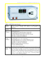
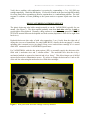
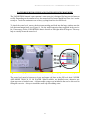
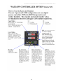
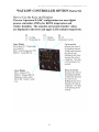
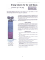
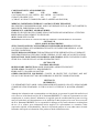
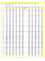
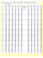
VAPORTRON ® H100BL/H100CL
Series Precision Humidity Lab
P
P
Users Guide – January 2012
BUCK RESEARCH INSTRUMENTS, LLC
PO Box 19498
Boulder, CO 80308
© 2012. Buck Research Instruments, LLC All rights reserved
Buck Research Instruments, LLC - VAPORTRON® H100BL/H100CL Series
Table of Contents
1. INTRODUCTION
Overview
Specifications
2. THEORY OF OPERATION
Philosophy of Design
Relationship Between Dewpoint and Relative Humidity
3. INSTRUMENT DESCRIPTION
Thermal Control System
Humidity Control System
4. SETUP AND VERIFICATION
5. USE AND CALIBRATION
General Practices
Calibration
Calibration of Sensors and Transmitters with the VAPORTRON
Recommended Calibration Procedure (or Trial-Run)
Sensor Response Analysis
Sensor/Transmitter Adjustment Procedure
Special Low-End Trim
Other Guidelines
Operating at High Relative Humidity
Desiccant/Drier Cartridge Service
Water Reservior Check and Water Service Procedure
6. TROUBLESHOOTING
Chamber Too Moist or Too Dry
Chamber Too Moist – No Control
Chamber Too Dry – No Control
No Control – L1, L2 Pump LEDs Lit
APPENDIX
Watlow Controllers
Material Safety Data Sheets
Sample Certificate of Calibration
Humidity Related Tables
Product Listing
Warranty
1
3
3
3
3
3
3
5
6
8
10
12
12
12
12
13
13
14
15
15
15
16
17
18
18
18
19
19
20
22
26
27
29
30
Buck Research Instruments, LLC - VAPORTRON® H100BL/H100CL Series
Appendix
Watlow Controllers
Material Safety Data Sheets
Sample Certificate of Conformance
Humidity Related Tables
Product Line Description
2
Buck Research Instruments, LLC - VAPORTRON® H100BL/H100CL Series
1. INTRODUCTION
Overview
The VAPORTRON series calibration system is a high-performance, stand-alone
temperature/humidity reference generator. It features a thermal servo system to stabilize
temperature in the range of 15 to 60°C at ± 0.2°C stability. Relative humidity is rapidly
generated in range of 3 to 95%RH at ± 0.2% RH stability. RH accuracy is ±1.5% at
maximum between 20-90% RH At temperatures near ambient, a typical accuracy of +/- 1%
RH is achieved. The chamber volume is 2 liters in a 12 cm (5 inch) diameter by 34 cm (7
inch) cylindrical space.
A thermoelectric cooler provides a means of stabilizing the chamber working temperature
at a differential centered near the ambient air conditions in the room..
The servo based humidity control provides a system with the precision needed for
laboratory and research needs. It also provides the overdrive required for production
operations where large surface area or multiple sensor calibrations are processed. Due to
the design of VAPORTRON, the typical settling time to a 1% RH stability is only 2-3
minutes.
Specifications
MODEL #
OPTIONS
15-60°C at ±0.2°C stability,
as above with Watlow 96 PID, serial data link,
RH & Temp, & software
H-100BL
H-100CL
2. THEORY OF OPERATION
Philosophy of Design
The VAPORTRON system was developed around a solid-state capacitive polymer sensor. This
philosophy differs somewhat from conventional humidity generators as we rely on a carefully
calibrated transfer-standard (the polymer) instead of "first principal" methods, i.e. gravimetric,
two-pressure, divided flow, dewpoint referenced feedback, etc. The VAPORTRON system
excels for the following reasons:
•
•
We generate relative humidity directly (via servo action against the reference), thus no
calculations or conversions are required to read out the chamber humidity. The chamber
environment is AT the humidity displayed on the readout panel.
The reference sensor output is monotonic. There is no secondary control system to hamper or
distort the sensor response to changes in moisture. This provides for a controlled, rapid
approach to the desired humidity and a stable humidity output thereafter.
3
Buck Research Instruments, LLC - VAPORTRON® H100BL/H100CL Series
•
There is no phase change ambiguity or oscillation introduced when the dewpoint, measured
or generated, goes below 0 °C.
•
A wide dynamic range of chamber output is possible. The 2-98% RH range corresponds to a
-24 to +24 ºC dewpoint range.
•
The polymer is immune to dust and salt contamination and requires little maintenance. A six
month to one year service period is typical for 1% accuracy.
•
The polymer reference sensor is approximately 1/10th the cost of a chilled mirror hygrometer
of similar sensing accuracy. It is compact, rugged, and produces no waste heat in the
chamber. This allows us to offer a complete temperature controlled generator package for a
price comparable to our most affordable chilled mirror hygrometer.
•
The VAPORTRON system takes advantage of the high stability and physical durability of the
world's best polymers. Only ROTRONIC premium sensors meet the stringent standards
required for use in the VAPORTRON.
•
This system was designed with generation of relative humidity as a major concern. For this
reason, it excels at development, calibration and evaluation of other RH sensors. The great
speed and precision of the VAPORTRON servo type generator saves both time and cost.
•
VAPORTRON is ideal for industrial or commercial transmitter calibrations where multiple
sensors can be calibrated at once, with exceptionally low unit-to-unit variation.
As standard final certification, we verify each VAPORTRON output RH using a CR-4 chilled
mirror hygrometer and a Rotronic Hygropalm. Both hygrometers support better than 1% RH
accuracy in this range. This comparison allows NIST traceability for our systems.
Relationship between Dewpoint and Relative Humidity
Figure 1 was calculated from the Clasius-Clapeyron general equation with the Goff-Gratch
equivalent integration, and used in a computer program developed at Buck Research. Shown is
the exponential dependence of dewpoint when RH is used as the reference input (or vice versa).
This curve should be consulted when trying to cross -reference humidity measuring instruments
of different types.
As can be seen, when generating high RH levels, a corresponding high accuracy should be
realized in dewpoint (due to the shallow slope). Conversely, a small RH change at the dry end
can result in large dewpoint changes.
4
Buck Research Instruments, LLC - VAPORTRON® H100BL/H100CL Series
Figure 1. Relative humidity vs. dewpoint at a fixed air temperature of 25 °C
3. INSTRUMENT DESCRIPTION
Figure 2 shows the 2.0 L working volume of the chamber. It consists of a 12 cm diameter by 34
cm long insulated plastic cylinder. The chamber is designed as an isothermal mixing vessel with
a small turbo-axial fan stirring air inside it. A high-efficiency heat sink is situated near the main
cabinet fan (outside of chamber) for thermal exchange of heat to/from the outside. Located
between the chamber internal heatsink and the cabinet heat-sink is a high capacity Peltier cooler
(Model -Ll single stage, -L2 dual stage) which is operated conservatively at 5 volts and
approximately 2.5 to 5 Amps (15 to 30 watts).
Figure 2 Photo of inside of the 2 liter workspace. RH reference sensor is on top, PT-100 sensor
is on the bottom
5
Buck Research Instruments, LLC - VAPORTRON® H100BL/H100CL Series
Thermal Control System
The thermal design of the VAPORTRON is depicted in Figure 3. The chamber temperature is
maintained by a Watlow series 965 (for -BL models) and Watlow 96 (for -CL models) microprocessor based PID controller (see Appendix for details on Watlow controllers). The controllers
measure a platinum resistance sensor element that is placed in the chamber vessel near the rear
center. Chamber setpoint is made via the controller digital front panel, which has a 0.1 °C
resolution. The PID controller maintains the chamber internal air temperature at a +/- 0.1 °C
stability.
The PID controller applies PWM (pulse-width-modulation) signals to the bases of a power
MosFET driver transistor array. The FETS operates as current switches to the Peltier module
attached to the chamber heat-sink. The Peltier module’s heat-pumping is automatically bidirectional in polarity. That is, either heating or cooling is possible, depending on environmental
conditions. This configuration allows the maximum thermal efficiency as well as fastest chamber
temperature rate of change when needed.
The PID controller can be set from 0 to +50°C (60°C for –L2) by simply pressing the up or down
arrows to change the setpoint. The chamber will typically arrive at a new stable temperature
within 3 to 5 minutes after changing the command value. Up to 20 minutes should be allowed at
the coldest and warmest program temperatures. The “M” and "A/M" buttons are disabled and
have no function in this configuration.
The temperature output of the temperature sensor in the Rotronic probe is amplified and scaled to
degrees celcius ranges and is available at the rear panel as a recordable analog output The range
is 0-5 V for 0 to 100°C
6
Buck Research Instruments, LLC - VAPORTRON® H100BL/H100CL Series
Figure 3. Thermal design concept diagram for VAPORTRON.
7
Buck Research Instruments, LLC - VAPORTRON® H100BL/H100CL Series
Humidity Control System
The VAPORTRON humidity control scheme is essentially a reference based, closed loop servodemand flow network (see Figure 4). After being thermally stabilized by the system described in
Figure 4, the working volume (2.0 Liters) is essentially a continuously stirred constant
temperature atmosphere. The present relative humidity is sensed by a high grade, fast response
polymer type reference sensor located approximately in the center rear third of the chamber. The
RH signal is compared by an error amp processor inside the RH PID controller to its LED
indicated set-point (command) as input by the user.
Rotronic Hygroclip
S or S2
Figure 4. VAPORTRON H-100 B Humidity Control Drawing.
If the chamber RH compares lower than desired, a proportional PWM signal is output by the
controller to a solid state 120 VAC (or 230 VAC for non-US models) relay which in turn feeds a
small AC type diaphragm pump (PW). The pump draws chamber air, pumps it through the
specially designed saturator vessel and outputs it back into the chamber. The output is vented
directly into a 20 lpm internal circulator fan such that rapid molecular mixing occurs inside the
chamber working volume.
8
Buck Research Instruments, LLC - VAPORTRON® H100BL/H100CL Series
Conversely, if the reference sensor senses a humidity that is moister than the present setpoint, a
PWM error signal is output by the controller to another SSR which in turn powers a separate
pump. The PD pump flow is essentially in parallel with the wet side, but they do not operate at
the same time. The dry side pump feeds chamber air into a Calcium Sulfate filled cartridge which
dries the air to a 0.2% RH or a dewpoint of approximately -40 C. Molecular sieves can also be
used in the cylinders for better dry-end performance. Silica-gel, while slightly less efficient, can
be used for minimum particulate generation when feeding Raoult-sensitive sensors. Finally the
air is again mixed thoroughly with the chamber air upon its entrance.
Because of the servo nature of this system, the chamber responds rapidly to either a change in
setpoint or a sudden change in chamber humidity loading. The servo pumps provide an ample
overdrive capability such that only 2-3 minutes are required for most step changes in command
value. At the extreme ends (<10% and > 90% RH) the system can take 10-15 minutes to reach
the desired humidity. This is due to reduced drive differential and chamber container (and any
contents) surface uptake/outgassing at each end of humidity extremes.
Typical control errors (deviation from setpoint) are +/- 0.1% RH from 10 to 90% RH setpoint to
around 1% error at the ends of the controlled range (3 to 98% RH). To allow for near 100% RH
at chamber temperatures of 25 C and above, the vapor saturator is electrically heated.
Additionally, a very low heat is maintained on the saturator delivery plumbing to ensure that
condensation limits are above ambient temperature.
9
Buck Research Instruments, LLC - VAPORTRON® H100BL/H100CL Series
4. SET UP AND VERIFICATION
The VAPORTRON control functions are shown in Figure 5. A description is listed roughly from
Left to Right in Table 2. See Appendix (pages A-1 and A-2) for detailed description of
temperature and RH controllers.
1. Unpack the VAPORTRON from the shipping carton and protective carrying case.
2. Remove the power cord and desiccant cartridge from side pouch and make sure the line
voltage is correct. Plug power cord into power outlet.
3. Unfold desiccant holder hooks at rear panel, install fresh cartidge and connect plastic hoses to
each end of the cartridge. (Place silver cap to INSIDE end of machine).
4. Switch on POWER (lower left). Both “RH DISPLAY” (green upper digits) and
“TEMPERATURE” display (red upper digits) should read the approximate room conditions.
Open white chamber for a few seconds. The RH reading should rise a few percent as the
internal reference sensor responds to your skin humidity.
5. Replace door and install rubber stopper in aluminum port fitting (a test sensor may be
inserted instead; seal around any cracks using the clay as provided in the kit).
6. Switch on “CONTROL”. A muffled, high pitched sound should indicate proper operation of
air circulator fan inside the chamber. The command or setpoint is read and adjusted in the
lower displays. Press the UP and DOWN ARROWS to change the command humidity – set
the RH command between 20 and 80% RH and allow 5 seconds for the new command to be
updated. The setpoint for temperature is similarly adjusted using the UP and DOWN
ARROWS. Set point is read off the lower display. Use a set point of 25.0 C to start out (i.e.
use a value close to ambient temperature).
7. The VAPORTRON displays should begin to ramp toward the values that were set. Normally,
the RH reading will stabilize within 10-60 seconds when the value desired is within 10% to
90% RH. The red L1 and L2 LEDs (right side or top of each controller) will indicate when
moist or dry air is pumping into the chamber.
8. The temperature control may take from a few minutes up to approximately 15 minutes near
the extreme range ends. At room temperature, normal achievable control control range in the
chamber is 15 to 50oC (L1), 10 to 60oC (L2).
9. The VAPORTRON has been filled with an adequate supply of distilled water for
approximately 1 month of normal operation. However, check the rear panel reservior
window weekly.
10
Buck Research Instruments, LLC - VAPORTRON® H100BL/H100CL Series
Figure 5. VAPORTRON H-100BL front panel.
Table 2. VAPORTRON control functions
POWER
Powers up all measuring and readout displays. All control systems are
SWITCH
disabled. Chamber is "floating" and is allowed to reach equilibrium with
ambient air.
CONTROL
Enables both temperature and RH Controllers. Turns on internal chamber fan.
SWITCH
RH
(Watlow model 965A)
CONTROL
TOP GREEN LED; 0-100% RH display of chamber RH
LOWER GREEN LED: RH command or setpoint value
UP/DOWN ARROWS: press to raise or lower RH command
DRY AIR; is on when red L2 led blinks on
WET AIR; is on when red Ll led blinks on
TEMPER(Watlow model 965A)
ATURE
TOP RED LED; 0-50 ºC (L1) air temperature
CONTROL
BOTTOM RED LED; 0-50 ºC air temp COMMAND VALUE
UP/DOWN ARROWS: press to increase or lower temperature
COOLING: is on when red Ll led blinks on
HEATING: is on when red L2 led blinks on
DISPLAY RANGE: limited to 0 to 50 (or 60) ºC.
ACTUAL CONTROL RANGE:
15 TO 50 ºC (L1), 10 TO 60 ºC (L2)
CHAMBER
The main circular door is approximately 5 inches on the inside. The door is
DOOR AND normally fitted with a single 25 mm (actually 26 mm clearance) gland sealed
PORTS
type access fitting. optionally, two ports can be supplied on the door. Port
fitting size adaptors are available for most commonly available sensor probes,
typically; 12, 13 mm; TESTO and VAISALA small diameter 3/8 inch; Hy-cal
probes 15, 16 mm; Rotronic small probes 18 mm ; Vaisala large (HMP-35
series) 20, 21 mm; TESTO large diameter
11
Buck Research Instruments, LLC - VAPORTRON® H100BL/H100CL Series
5. USE AND CALIBRATION
General Practices
For best dewpoint accuracy, the user is urged to use the output from the air-immersed PRT
temperature sensor that is co-located with the RH sensor. This allows for actual AIR
temperatures to measured from the place where the RH level is slaved.
Some general practices to observe include:
•
To minimize mixing with ambient air and RH over/underload, temporarily shut off the
Control Switch when opening chamber door.
•
Keep RH setting low (20-30%) when changing chamber temperatures ESPECIALLY WHEN
COOLING DOWN.
•
Before chamber shutdown, set RH to a low value (20-30%) to avoid condensation inside
chamber during storage.
•
Replace humidifer level with distilled water as required (typically once per month is
adequate).
•
Use LAB ALGAECIDE or 1 DROP of Clorox (chlorine bleach) per filling to inhibit mold.
The water tank is accessed by removal of red rubber cap at the center of the rear panel.
•
Add water slowly with a small syringe. Typically, add only 20 cc of water. * WARNING * IF
THE WATER LEVEL IS OVERFILLED (SEE ROUND WINDOW AT BOTTOM REAR
PANEL) LIQUID WATER MAY BE INADVERTENTLY PUMPED DIRECTLY INTO
THE CHAMBER WORKING VOLUME! ** BE CAREFUL**
Calibration
CALIBRATION OF SENSORS AND TRANSMITTERS WITH THE VAPORTRON
In the past, the most widely used method for RH calibration has been with saturated salts. With
salts, it is possible to attain sub 1% RH accuracies but usually at the expense of a lot of time
spent on the slow equilibration times, especially above the 75% RH level.
An additional related problem is that most sensor/electronic combinations exhibit interactions
between the calibration adjustment points. When long times are needed for the salt and the sensor
to stabilize, it is not usually time-efficient to properly address the interaction problem (i.e.
through iteration).
With the VAPORTRON system, we have chosen to accept slightly less final generation accuracy,
(circa 1.5%) but to greatly accelerate the time to change RH values and associated settling times.
12
Buck Research Instruments, LLC - VAPORTRON® H100BL/H100CL Series
The VAPORTRON stabilizes to a new RH value from 10 to 100 times faster than most salt
derived methods. The benefit of this is that the product of calibration throughput and final
accuracy is greatly enhanced.
In addition, due to the speed of generation, it is possible (and normally expected in metrology
practice) to provide an “as found-as left" record of sensors tested, so that post-deployment
corrections can be applied if needed to the sensor data.
One other advantage is that (especially through automated ramp and soak option) it is easier to
identify faulty or non-linear sensor output and deal with it BEFORE a lot of personnel time is
wasted on attempting calibration of a malfunctioning sensor!
RECOMMENDED CALIBRATION PROCEDURE (OR TRIAL-RUN)
For a typical "as found" or exploratory run, we advise to start at low RH (typically 20 or 30%
RH). Allow the Devices Under Test (DUT's) to sit in the VAPORTRON chamber for 2 minutes
for every Deg C difference between room temperature in the lab and the VAPORTRON chamber
temperature. As a rule of thumb -- 5 minutes is usually enough at low RH. Once the temperature
is fully stable (use the readings of the DUT's temperature output if available) follow the
procedure below:
1. Note or log sensor readings at the low RH
2. Command a mid-range RH value of 50% RH and after 5 minutes (minimum) and record
sensor readings.
3. Command a high-scale or "span-check" of 70 to 80% RH and allow another 5 minutes, again
record the sensor values.
4. Finally, set the VAPORTRON for an RH of 90 or 95% and allow the sensors approximately
10-15 min to "soak". Record the sensor readings after 5 minutes and again at 15 minutes.
Most normal RH polymers will show a small upward "creep". However, this change in RH
should be less than 0.5% RH.
5. Return the VAPORTRON RH to the initial low RH and allow 10 minutes for full
stabilization.
SENSOR RESPONSE ANALYSIS
Plotting the four recorded measurements from the calibration procedure on a linear-linear graph
will make it easier to determine if sensor adjustments are necessary. The lines behavior and
suggested adjustments are as follows:
If a DUT output shows a constant "offset" to a perfect 1:1 line (curve A on Figure 6) - adjust the
DUT’s "zero" or "low RH" potentiometer.
If a DUT shows an output that crosses the straight line but is either flatter or steeper than 1:1
(curve B on Figure 6) – adjust both the DUT’s "zero" and "span" (or "HIGH") potentiometer.
If a DUT shows a "hump", “sag”, or severe non-linearity through the middle of the range (or
excessive slope above the 75% to 95% range) then an iterative/compromise set of adjustments
13
Buck Research Instruments, LLC - VAPORTRON® H100BL/H100CL Series
will need to be made to get a best fit. If it is necessary to have the ideal sensor response at a
restricted RH range, the non-linearity may be ignored.
Sensor Linearity Graph
Ideal (1:1)
100
90
B
RH Reading (%) - Sensor
80
70
Ideal (1:1)
60
A
B
A
50
C
C
40
30
20
10
0
0
20
40
60
80
100
Actual RH (%) - VAPORTRON
Figure 6. Sensor linearity curves. Sensor curve A can be corrected by adjustment of “offset”
only. Sensor curve B can be corrected by both “offset” and “span” adjustment. Sensor curve C
linearity cannot be corrected, however closer average agreement to “ideal” can be made by
lowering “offset” and raising the “gain” setting slightly.
SENSOR/TRANSMITTER ADJUSTMENT PROCEDURE
Once a preliminary analysis is made through the pre-calibration and exploratory runs, use the
following steps to calibrate the sensor/transmitter:
1. Adjust each DUT's "low" or "zero" to within 1% of the actual VAPORTRON RH. (Assuming
you are still at the 20-30% RH step)
2. Set the VAPORTRON to the "high" end point where you want to optimize the slope or
"span" of the sensor (i.e. 75 to 80% RH), allow 10 minutes soak time, then adjust the "gain"
or ''span" potentiometer of the DUT for within 1% of actual RH.
3. Return to the dry end, wait 5 minutes and make a final (usually < 0.5%) adjustment to the
"zero" adjustment.
4. If necessary, return to the High RH and make a final trim to the span.
14
Buck Research Instruments, LLC - VAPORTRON® H100BL/H100CL Series
5. Set the VAPORTRON to mid-scale (50%) and allow sensors to stabilize. It is at this point
that true sensor linearity can be tested and any compromise adjustments can be contemplated.
Usually the "low" or "zero" adjustment is may now be trimmed to allow for a
"split-the-difference" trade-off deviation to be made for the low and high-end RH regions.
SPECIAL LOW-END TRIMS
Some sensor/transmitters, especially for industrial ovens or dryers will have an additional
adjustment for the very dry end of the RH spectrum (usually in the 5 to 10% RH range). Once the
general output is adjusted as per the above sequence, it is safe to make minor adjustment trims by
setting the VAPORTRON to approximately 10% RH and allowing 15 minutes for dryout, then
adjusting the special "LOW" or "DRY" potentiometer. If a total change is 5% or more in this
region, it is advised to again return to the normal 20-30% range to verify that circuit interaction is
not excessive (> 0.5 to 1%).
Other Guidelines
OPERATING AT HIGH RELATIVE HUMIDITY
This calibration chamber is designed for optimum performance near or slightly above the
ambient air temperature. The unit will generate RH at cooler and warmer temperatures but at
some sacrifice in the range of humidity output. (The RH range that is possible will be narrowed
at both the moist and dry ends by 10% or more.)
When operating the system at very high RH levels (>90%), it is important to realize that
gradients in temperature (i.e. cold surfaces) can cause condensation of liquid water on that
surface. When this occurs, attempting to maintain or increase the RH setting will only cause
more condensation and the actual air-volume humidity will remain the same.
In other words, the limits of high RH operation will depend on how much cooling is being
demanded of the heat-exchanger. The most reliable way to get RH values above 90%RH is to set
the chamber temperature a little above ambient (1-2 ºC) and start by increasing the RH command
by 1%RH intervals. Each time after the %RH value stabilizes, decrease the %RH value by
1%RH. If the chamber responds quickly, then increase the RH command by 1%RH and continue
increasing the %RH value by 1%RH increments. When the chamber no longer quickly responds
to a decrease of 1%RH, then it is at or near physical saturation. It is also wise to make sure the
chamber is stable and not oscillating or ramping in temperature when running at high RH levels.
15
Buck Research Instruments, LLC - VAPORTRON® H100BL/H100CL Series
Verify that a problem with condensation is occuring by commanding a -5 to -10% RH step
setting temporarily. Watch the RH display. If it freezes or holds at the previous high RH reading
for a long time before responding to the new setpoint there is a condensation problem. The slow
response is evidence of water puddling as the system waits to evaporate liquid water from the
walls.
DESICCANT/DRIER CARTRIDGE SERVICE
The plastic desiccator tube holds enough material to run the VAPORTRON typically for one
month. (See Figure 7). The dryer material gradually turns from dark blue when dry to pink or
greyish white when depleted. Normally a sharp contrast is seen when using granular CALCIUM
SULFATE material between the depleted and fresh section (depletion is from left to right from
back view).
Replenish desiccant when edge of pink color approaches 2 cm (1 inch) from the right end of
drying tube (on rear of instrument); use only DARK BLUE, ultra dry desiccant (approx. 1 month
operating time is normal service per charge). Keep covers on desiccator cartridge if it is stored
while NOT connected to the VAPORTRON system hoses.
For VAPORTRONs with the dew point option (-DP), we normally supply the desiccator tube
filled with ½ molecular sieve and ½ calcium sulfate . The molecular sieve dries the air by a
mechanical method as opposed to chemical and is less “dusty”. This allows longer use of chilled
mirrors before mirror contamination occurs. We advise to change the desiccant at 1 inch to left
of the red line when using the molecular sieve filled drier cartridges.
Figure 7. Rear panel with desiccant cartidge correctly installed.
16
Buck Research Instruments, LLC - VAPORTRON® H100BL/H100CL Series
WATER RESERVIOR CHECK AND WATER SERVICE PROCEDURE
The VAPORTRON internal vapor saturator/ water reservior is designed for long service between
re-fills. Depending on the amount of use, the normal refill of water should last from 4 to 6 weeks
to only to 1 week for continuous use or heavy cycling from hi to low RH levels.
To check the water level, remove the desiccant cartridge and look into the large window near the
left desiccant hangar hook (see Figure 8). Use the small inspection lamp supplied in the service
kit. If necessary, tilt the VAPORTRON chassis fore/aft or left/right about 20 degrees. This may
help to visually locate the water level.
Figure 8. Water guage window location (left). Detailed figure of guage window decal (right).
The water level must be between to lower and upper red lines on the fill level decal. NEVER
ADD MORE THAN 30 CC OF WATER. When available, use distilled water, otherwise use
clean tap water or bottled water. A blunt-needle syringe was included in the service kit to aid in
filling the reservior. Always re-install the small cap after adding water.
17
Buck Research Instruments, LLC - VAPORTRON® H100BL/H100CL Series
6. TROUBLESHOOTING
In normal operation, the control system will respond quickly to bring the RH reading to very
close to the digital command LED setting. If the pumps run for a long time and/or the RH
reading does not quickly settle in, it could be caused by the following: (First, shut off main power
for 1 second, then back on. This action assures immediate re-entry of correct setpoints in case the
system has been left idle with the CONTROL switch off.)
CHAMBER TOO MOIST OR TOO DRY
Possible Cause
Suggested Action
Leaks in or near the chamber door or through Check and apply clay or tape shut.
rubber port gland or rubber stopper.
Open return fitting (no cover or hose on fitting) Replace cover or tape the fitting shut.
on "SAMPLE RETURN".
Abnormally cold or hot chamber temperatures. Bring chamber close to ambient temperature,
see if control improves.
CHAMBER TOO MOIST - NO CONTROL
Possible Cause
Condensation on chamber walls.
Suggested Action
Open chamber, wipe walls with dry cloth,
allow to air-dry for 5-10 minutes.
Desiccator cartridge used-up (all pink or grey Check desiccator cartridge. Replace if all pink
in color) or has become physically or grey. Reconnect hose if disconnected.
disconnected from the chamber hoses. * Note
that the system can actually work without the
dryer connected, but the chamber will be
limited to = or > than whatever the prevailing
room humidity is!
Hygroscopic load! Some materials have Remove any objects you suspect could be too
TREMENDOUS water capacity in the vapor hygroscopic.
phase, eg; Nylons, PVC plastics, and woods
etc.
18
Buck Research Instruments, LLC - VAPORTRON® H100BL/H100CL Series
CHAMBER TOO DRY -- NO CONTROL
Possible Cause
No liquid water in saturator vessel
Suggested Action
Check back sight glass and tilt cabinet front to
back to confirm the water level
Cabinet of VAPORTRON unit too cold
Allow system to run in the power-on only (no
control) for a period of time.
Hygroscopic load! Some materials have Remove suspect material
TREMENDOUS water capacity in the vapor
phase, eg; Nylons, PVC plastics, and woods
etc.
NO CONTROL -- L1, L2 PUMP LEDS LIT, BUT NO REGULATION
Possible Cause
"CONTROL" switch not activated.
Electronic failure.
Suggested Action
Check that it is pressed on
Consult technical documents or the factory
19
Buck Research Instruments, LLC - VAPORTRON® H100BL/H100CL Series
20
Buck Research Instruments, LLC - VAPORTRON® H100BL/H100CL Series
21
Buck Research Instruments, LLC - VAPORTRON® H100BL/H100CL Series
22
Buck Research Instruments, LLC - VAPORTRON® H100BL/H100CL Series
23
Buck Research Instruments, LLC - VAPORTRON® H100BL/H100CL Series
MATERIAL SAFETY DATA SHEET
IDENTITY: INDICATING DRIERITE
DESCRIPTION: 1/16" TO I/4" BLUE GRANULES
DATE PREPARED: 7-9-96
SECTION I
MANUFACTURER'S NAME: W. A. HAMMOND DRIERITE CO., LTD
ADDRESS: P. 0. BOX 460, 138 DAYTON AVE. XENIA, OH 45385
EMERGENCY PHONE NUMBER: (513) 376-2927
INFORMATION PHONE NUMBER: (513) 376-2927
SECTION II
INGREDIENTS
OSHA PEL ACGIH TLV UNITS
C.A.S. #
10
mg/m3
7778-I8-9
0.05*
mg/m3
7646-79-9
CHEMICAL IDENTITY
%
CALCIUM SULFATE 97
15
COBALT CHLORIDE 3
0.05*
*(AS COBALT METAL)
HAZARDOUS MATERIALS IDENTIFICATION SYSTEM (HMIS)
HEALTH
FLAMMIBILITY
REACTIVITY
PROTECTIVE EQUIPMENT
1
0
1
E
SECTION III
PHYSICAL/CHEMICAL CHARACTERISTICS
SPECIFIC GRAVITY: (H20=1): 1.87
SOLUBILITY IN WATER: 0.25 GRAMS PER LITER
MELTING POINT: 1450 oC DECOMPOSES
APPEARANCE: BLUE GRANULES; NO ODOR
SECTION IV
FIRE AND EXPLOSION HAZARD DATA
FLASH POINT: NONE
EXTINGUISHING MEDIA: NOT COMBUSTIBLE
SPECIAL FIREFIGHTING PROCEDURES: NONE
UNUSUAL FIRE AND EXPLOSION HAZARDS: NONE
SECTION V
REACTIVITY DATA
STABILITY: STABLE
INCOMPATIBILTY (MATERIALS TO AVOID): STRONG ACIDS
HAZARDOUS DECOMPOSITION BYPRODUCTS: CL2 AT 318o; S03 @ 1450 oC
HAZARDOUS POLYMERIZATION: WILL NOT OCCUR
SECTION VI
HEALTH HAZARD DATA
EYES: PARTICLES MAY CAUSE IRRITATION.
SKIN: THIS MATERIAL IS NOT TOXIC. MAY DRY OR IRRITATE SKIN
INHALATION: MAY CAUSE AN IRRITATION OF RESPIRATORY ORGANS OF SENSITIVE
PERSONS RESULTING IN THE OBSTRUCTION OF AIRWAYS WITH SHORTNESS OF BREATH.
INGESTION: MAY CAUSE VOMITING, DIARRHEA AND SENSATION OF WARMTH
SIGNS AND SYMPTOMS OF OVER EXPOSURE: EYE, NOSE, THROAT, OR RESPIRATORY
IRRITATION
24
Buck Research Instruments, LLC - VAPORTRON® H100BL/H100CL Series
CARCINOGENICITY OF INGREDIENTS:
MATERIAL
IARC
NTP
OSHA
CALCIUM SULFATE, NOT LISTED NOT LISTED NOT LISTED
COBALT CHLORIDE YES*
NO
NO
*(COBALT & COBALT COMPOUNDS ARE CLASSIFIED AS GROUP 2B)
MEDICAL CONDITIONS GENERALLY AGGRAVATED BY EXPOSURE:
PRE-EXISTING UPPER RESPIRATORY AND LUNG DISEASE SUCH AS, BUT NOT LIMITED TO,
BRONCHITIS, EMPHYSEMA & ASTHMA
EMERGENCY AND FIRST AID PROCEDURES:
EYES: FLUSH WITH WATER. IF IRRITATION CONTINUES OBTAIN MEDICAL ATTENTION.
DUST: INHALATION: REMOVE TO FRESH AIR
SKIN: WASH WITH WATER
INGESTION: IF PATIENT IS CONSCIOUS, INDUCE VOMITING. OBTAIN MEDICAL ATTENTION.
SECTION VII
SPILL AND LEAK PROCEDURES
STEPS TO BE TAKEN IN CASE MATERIAL IS RELEASED OR SPILLED: SWEEP OR
VACUUM MATERIAL INTO APPROPRIATE WASTE CONTAINER FOR DISPOSAL. AVOID
DUSTING CONDITIONS.
WASTE DISPOSAL METHOD: THIS MATERIAL MUST BE DISPOSED OF IN ACCORDANCE
WITH PROCEDURES ACCEPTABLE UNDER. FEDERAL, STATE AND LOCAL REGULATIONS.
PRECAUTIONS TO BE TAKEN IN HANDLING AND STORING: KEEP CONTAINER CLOSED
STORE IN A COOL DRY PLACE AVOID GENERATING DUST
SECTION VIII
CONTROL MEASURES
RESPIRATORY PROTECTION: MASK NIOSH/OSHA APPROVED FOR DUST
VENTILATION: TO MEET TLV REQUIREMENTS
EYES: SAFETY GLASSES OR GOGGLES
OTHER PROTECTIVE EQUIPMENT: GLOVES OR PROTECTIVE CLOTHING ARE NOT
USUALLY NECESSARY BUT MAY BE DESIRABLE IN SPECIFIC WORK SITUATIONS.
SECTION IX
REFERENCES
U.S. DEPARTMENT OF LABOR - OSHA FORM APPROVED OMB NO.1218-0072. OSHA HAZARD
COMMUNICATION STANDARD - 29 CFR 1910.1200 U.S GYPSUM CO. & SOGEM-AFROMET
INC.
Although the information and recommendation set forth herein are presented in good faith and believed
to be correct as of the date hereof, the W.A. Hammond DRIERITE Co. makes no representation as to the
completeness or accuracy thereof. Information is supplied upon the condition that the person receiving
same will make their own determination as to its suitability for their purpose prior to use. In no event will
the W.A. Hammond DRIERITE Co. be responsible for damages of any nature whatsoever resulting from
the use of or reliance upon information herein supplied. No representations or warranties, either
expressed or implied, of merchantability, fitness for it particular purpose of or any other nature are made
hereunder with respect to information or the product to which information refers.
25
Buck Research Instruments, LLC - VAPORTRON® H100BL/H100CL Series
CERTIFICATE OF CONFORMANCE
Customer Name
Serial #
Model #
VAPORTRON
NIST TRACEABLE
STANDARD %RH
11.4
32.7
48.2
57.7
75.3
84.2
CUSTOMER UNIT
%RH
11.0
32.2
48.4
58.0
74.5
83.2
Date
2K-0104-TD100XXXXX
Hygroclip S 11XXXX
DIFFERENCE
-0.4%RH
-0.5%RH
+0.2%RH
+0.3%RH
-0.8%RH
-1.0%RH
SPECIFICATION OF UNIT
± 1.5%RH
± 1.5%RH
± 1.5%RH
± 1.5%RH
± 1.5%RH
± 1.5%RH
NIST TRACEABLE CALIBRATION EQUIPMENT
Humidity Standard
Manufacturer
Buck Research Instruments
Model
CR-3
Cal Due
2/1/2006
Serial #
301
Temperature Standard
Manufacturer
Logan
Model
PlatinumRTD
Cal Due
3/15/2006
Serial #
9251-12
Voltage Standard
Manufacturer
Agilent
Hewlett Packard
Model
34401A
34401A
Cal Due
5/27/2006
5/27/2006
Serial #
US36112687
US36043947
Pressure Standard
Manufacturer
Druck
Model
DPI-740
Cal Due
2/12/2006
Serial #
740 01260
TESTED BY: ________________________
PO Box 19498, Boulder, CO 80308
main: 303.442.6055
fax: 303.443.2986
1.800.HUMIDITY
WWW.HYGROMETERS.COM
26
05/03/2006
Buck Research Instruments, LLC - VAPORTRON® H100BL/H100CL Series
27
Buck Research Instruments, LLC - VAPORTRON® H100BL/H100CL Series
28
Buck Research Instruments, LLC - VAPORTRON® H100BL/H100CL Series
PRODUCT LISTING
TABLE-TOP HUMIDITY LABORATORY - VAPORTRON® H-100 SERIES
(line powered portables 115/230V 50/60HZ)
H-100BL
Basic unit with manual set-points and no computer interface.
RH range of 3-95 % RH, 10 to 60 Deg C
H-100CL
Advanced unit with manual/computer interface and PC
operated ramp & soak with logging to disk- file.
INSTALLED OPTIONS: Available in "BL". or "CL" version:
-230
-DP
-DPR
230VAC, 50Hz option (standard is 110VAC, 60Hz)
CiS dew point sensor with LCD readout and output
LCD dew point display from Rotronic Sensor
VAPORTRON ACCESSORIES AND SUPPORT ITEMS:
DRIER H-100
DOOR-OSTD
DOOR-1
DOOR-2
SPARES
H-100 MAN
DOOR-ESP
DOOR-ESP-4
RECAL
Desiccant cartridge
Blank insulated door
Standard single-port door; 25mm diameter fitting, insulated
Standard dual-port door; 25mm diameter fitting, insulated
Accessory kit for VAPORTRON
Operators' manual
Heavy duty 3/8” machined polycarbonate door with face o-ring seal and
thumbscrew lockdowns –blank –no holes -clear
Same as above with 4 drilled ports at 12-25 mm dia – clear
(customer specify each port diameter at order placement)
NVLAP certified calibration with documents
29
Buck Research Instruments, LLC - VAPORTRON® H100BL/H100CL Series
APPENDIX 3:WARRANTY
Manufacturer warrants that the items delivered shall be free from defects (latent and patent) in
material and workmanship for a period of one year after acceptance of the specific goods by
Buyer. The Buyer’s sole and exclusive remedy under this warranty shall be limited to repair or
replacement. Defective goods must be returned to the Manufacturer promptly after the discovery
of any defect within the above referenced one-year period. Transportation expenses to return unit
to Manufacturer shall be borne by the Buyer. Return shipping to Buyer shall be borne by
Manufacturer for valid warranty claims. This warranty shall become inapplicable in instances
where the items have been misused or otherwise subjected to negligence by the Buyer
NOTWITHSTANDING ANY OTHER PROVISION OF THIS CONTRACT, NO OTHER
WARRANTIES WHETHER STATUTORY OR ARISING BY OPERATION OF LAW,
EXPRESSED OR IMPLIED, INCLUDING BUT NOT LIMITED TO THOSE OF
MERCHANTABILITY OR FITNESS FOR PARTICULAR PURPOSE, SHALL APPLY TO
THE GOODS OR SERVICES PROVIDED HEREUNDER, OTHER THAN THE REPAIR
AND REPLACEMENT WARRANTY ABOVE . SELLER SHALL IN NO EVENT BE LIABLE
TO BUYER OR ANY THIRD PARTY FOR ANY DAMAGE, INJURY OR LOSS,
INCLUDING LOSS OF USE OR ANY DIRECT OR INDIRECT INCEDENTAL OR
CONSEQUENTIAL DAMAGES OF ANY KIND.
30