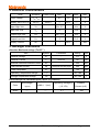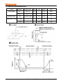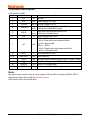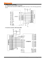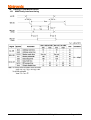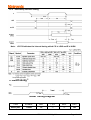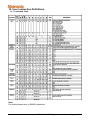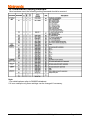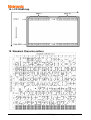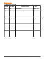
1
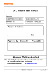
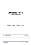
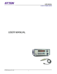
LCD Module User Manual
Customer
:
MASS PRODUCTION CODE
: TG320240A-05WA0
DRAWING NO.
: m-TG320240A-05WA0_A00
Approved By Customer:
Date:
Approved By
Checked By
Prepared By
Vatronix Holdings Limited
ADD:5F,No.10 Blg,WenGuang Industrial Zone,XiLi,Nanshan District,Shenzhen,China
TEL:0086-755-83234801 33207538 FAX:0086-755-33207539
E-mail:[email protected]
Http://www.vatronix.com
TG320240A-05WA0_A00
Page 1 of 14
Contents
1. Precautions in Use of LCD Module-----------------------------------P3
2. General Specification-------------------------------------------------------P3
3. Absolute Maximum Ratings-----------------------------------------------P3
4. Electrical Characteristics--------------------------------------------------P4
5. Backlight Information-------------------------------------------------------P5
6. Optical Characteristics-----------------------------------------------------P5
7. Interface Description--------------------------------------------------------P6
8. Contour Drawing & Block Diagram--------------------------------------P7
9. Application circuit----------------------------------------------------------P8
10. Timing Characteristics -----------------------------------------------P9
11. Reset timing -----------------------------------------------------P10
12. User instruction Definitions -------------------------------------------P11
13. Initialization Setting Example ----------------------------------------P12
14. LCD RAM map -----------------------------------------------------------P13
15. Standard Character pattern -------------------------------------------P13
16. Revision records------------------------------------------------------P14
TG320240A-05WA0_A00
Page 2 of 14
1. Precautions in Use of LCD Module
(1) Avoid applying excessive shocks to the module or making any alterations or
modifications to it.
(2) Don’
t make extra holes on the printed circuit board, modify its shape or change the
components of LCD Module.
(3) Don’
t disassemble the LCM.
(4) Don’
t operate it above the absolute maximum rating.
(5) Don’
t drop, bend or twist LCM.
(6) Soldering: only to the I/O terminals.
(7) Storage: please storage in anti-static electricity container and clean environment.
2. General Specification
ITEM
STANDARD VALUE
UNIT
Number of dots
320X240
Dots
Outline dimension
139.0(W)X120.0(H)X13.0MAX.(T)
mm
View area
103.0(W)X79.0(H)
(5.1 ")
mm
Active area
95.97(W)X71.97(H)
mm
Dot size
0.27 (W)X0.27(H)
mm
Dot pitch
0.30(W)X0.30 (H)
mm
LCD type
FSTN, Negative, transmissive
View direction
6 o’
clock
Backlight
White LED
Controller
RA8835
3. Absolute Maximum Ratings
ITEM
SYMBOL
MIN.
Operating Temperature
TOP
-20
Storage Temperature
TST
MAX.
UNIT
-
+70
℃
-30
-
+80
℃
VI
-0.3
-
VDD +0.3
V
Supply Voltage For Logic
VDD
0
-
5.5
V
Supply Voltage For LCD
VDD-VEE
0
-
30
V
Input Voltage
TYPE
TG320240A-05WA0_A00
Page 3 of 14
4. Electrical Characteristics
ITEM
SYMBOL
Logic Voltage
VDD-VSS
Supply Volt.For LCD
VDD-VO
CONDITION
Ta=25℃
MIN.
TYPE
MAX.
UNIT
4.5
5.0
5.5
V
---
25.0
---
V
Input High Volt.
VIH
-
VDD -2.2
-
VDD
V
Input Low Volt.
VIL
-
0
-
0.8
V
Output High Volt.
VOH
-
VDD –0.3
-
VDD
V
Output Low Volt.
VOL
-
0
-
0.3
V
Supply Current
IDD
-
---
---
mA
22.0
5. Backlight Information
Absolute Maximum ratings (Ta=25℃)
Item
Symbol
Conditions
Rating
Unit
Reverse voltage
Vr
-
5.0
V
Reverse Current
Ir
Vr=5.0V
80
uA
240
mA
240
mA
Absolute maximum forward Current
Ifm
Peak forward current
Ifp
Power dissipation
Pd
755
mW
Operating Temperature Range
Toper
-30~+80
℃
Storage Temperature Range
Tst
-40~+90
℃
I msec plus 10% Duty Cycle
0
Electrical/Optical Characteristics (Ta=25 C,If=240mA)
Color
White
Wavelength
λp(nm)
---
Spectral line half
widthΔλ(nm)
---
Operating Voltage(v)
(±0.15V)
3.1
TG320240A-05WA0_A00
Forward
Current (mA)
200
Page 4 of 14
6. Optical Characteristics
ITEM
SYMBOL
CONDITION
MIN
TYPE
MAX
UNIT
View Angle
(V)θ
CR≧2
10
-
120
deg.
(H)φ
CR≧2
-45
-
45
deg.
Contrast Ratio
CR
Ta=250C,Vop
4.0
5.5
8.0
-
Response Time
T rise
-
-
120
180
ms
T fall
-
-
140
210
ms
TG320240A-05WA0_A00
Page 5 of 14
7.Interface Description
LCD interface CON1:
Pin No.
Symbol
Level
1
VSS
0V
2
VDD
3
V0(Vlcd)
4
/WR(RW)
Description
Ground
5.0V Power supply for Logic
5
/RD (E)
6
/CS
-20.0V
L
(H/L)
L
(H/L)
L
7
A0
H/L
8
/RST
L
9~16
DB0~DB7
H/L
8-bit Data bus
17
18
SEL1
H/L
Microprocessor interface type:H:6800 ,L:8080
19
VEE
A(LED+)
20
K(LED-)
Driving voltage for LCD
8080 family:Write signal,active LOW
6800 family: Read/Write signal
8080 family:Read signal,active LOW
6800 family: Enable clock
Chip enable,active LOW
/RD=L /WR=H
A0=L: Data and cursor address Read
A0=H :Status read
/RD=H /WR=L
A0=L: Display data and parameter Write
A0=H :Command write
LCD reset,active LOW
Note*
-25V Negative voltage output (Optional)
+5V Anode of LED Backlight
0V
Cathode of LED Backlight
Note:
Microprocessor interface type is set by jumper J68 and J80 or setting by PIN18 “SEL1”
8080 family:J80=0 Ohms,J68 open.Default setting.
6800 family:J68=0 Ohms,J80 open.
TG320240A-05WA0_A00
Page 6 of 14
8. Contour Drawing & Block Diagram
TG320240A-05WA0_A00
Page 7 of 14
9. Application circuit
9.1 Interface with the 8080 family MPU
The LCD can be used with an 8080 family MPU as shown in the following application
circuit.
9.2 Interface with the 6800 family MPU
TG320240A-05WA0_A00
Page 8 of 14
10. Timing Characteristics
10.1
8080 family interface timing
TG320240A-05WA0_A00
Page 9 of 14
10.2
6800 family interface timing
Note:
tCYC6 indicates the interval during which CS is LOW and E is HIGH.
11. Reset timing
Reset Timing Diagram
ITEM
SYMBOL
MIN.
TYPE
MAX.
UNIT
Reset plus
Treset
1.0
---
---
ms
TG320240A-05WA0_A00
Page 10 of 14
12. User instruction Definitions
12.1 Command Table
Note:
For details,please refer to RA8835 datasheet.
TG320240A-05WA0_A00
Page 11 of 14
13. Initialization Setting Example
After hardware reset, the following setting command should be excuted.
Note:
1.For details,please refer to RA8835 datasheet.
2.It is an example only,these settings can be changed if necessary.
TG320240A-05WA0_A00
Page 12 of 14
14. LCD RAM map
15. Standard Character pattern
TG320240A-05WA0_A00
Page 13 of 14
16. Revision records
Version
Ref.page
A00
All
Reversion Items
New release
TG320240A-05WA0_A00
Date
2009.11.28
Page 14 of 14