1
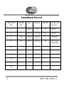
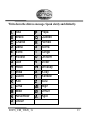
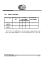
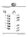
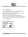
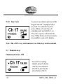
USERS MANUAL
Jotron AS
P.O. Box 54, NO-3280 Tjodalyng, Norway
Tel: +47 33 13 97 00 | Fax: +47 33 12 67 80
www.jotron.com
Tron TR20 GMDSS
Tron TR20 PLUS
www.jotron.com
EC Declarations of Conformity, available at www.jotron.com
Read this Users Manual fully to familiarise yourself with the
equipments functions and facilities.
Abbreviations and definitions
CLOCK
A precisely spaced, stable train of pulses generated within an electronic system
to synchronize the timing of digital operations within the system.
DEFAULT
A condition that the navigator assumes automatically if no other condition is
initiated by the operator.
DW
Dual Watch. Receiver altering between two different channels.
GMDSS
Global Maritime Distress & Safety System
IEC
International Electro-technical Commission.
IMO
International Maritime Organization
2
80078_UM_ TR20_ G
IP rating
Joint factor (to indicate the waterproofing of the equipment)
ITU
International Telecommunication Union.
LED
Light Emitting Diode.
SMA
SubMiniature version A connector
TW
Triple Watch. Receiver altering between three different channels.
VHF
Very High Frequency -A set of frequencies in the MHz region.
VSWR
Voltage standing wave ratio
80078_UM_ TR20_ G
3
Amendment Record
AMENDMENT
NO.
INCORP.
BY
REASON FOR
CHANGE
DATE
PAGE(S)
VERSION
1
10.09.03
10
D
EM4038
2
04.03.04
1-5, 8,10
E
EM4197
3
ES
03.10.06
56 total
F
CN 05309
4
ES
18.04.07
Total: 56
G
New company
name & logo
5
6
7
8
9
10
4
80078_UM_ TR20_ G
The information in this book has been carefully checked and is believed
to be accurate. However, no responsibility is assumed for inaccuracies.
CAUTION!
This equipment contains CMOS integrated circuits. Observe handling
precautions to avoid static discharges which may damage these devices.
Jotron AS reserves the right to make changes without further notice to any
products or modules described herein to improve reliability, function or design.
Jotron AS does not assume any liability arising out of the application or use of
the described product.
80078_UM_ TR20_ G
5
LIST OF CONTENTS
1 GENERAL DESCRIPTION............................................................................14
1.1
1.2
1.3
1.4
INTRODUCTION ...............................................................................................14
FEATURES.......................................................................................................15
LICENSING ......................................................................................................16
GETTING STARTED ..........................................................................................17
2 TECHNICAL SPECIFICATION ...................................................................18
2.1
2.2
2.3
2.4
3
GENERAL ........................................................................................................18
RECEIVER .......................................................................................................19
TRANSMITTER ................................................................................................19
CHARGER .......................................................................................................20
FUNCTIONAL DESCRIPTION...................................................................21
3.1
3.2
3.3
3.4
3.5
RADIO UNIT....................................................................................................21
AUXILIARY CONNECTOR .................................................................................22
ANTENNA .......................................................................................................22
BATTERY REMOVAL AND REPLACEMENT ........................................................23
PRIMARY BATTERY .........................................................................................24
3.5.1
Description ......................................................................................24
3.5.1.1
When to change battery ..............................................................24
3.5.1.2
Special care.................................................................................25
3.6 SECONDARY BATTERY AND CHARGER ...........................................................25
3.6.1
Using the NiMH battery ..................................................................25
3.6.2
Charging the secondary battery .......................................................26
6
80078_UM_ TR20_ G
3.6.3
Battery endurance............................................................................27
4 INSTALLATION .............................................................................................28
5 OPERATING INSTRUCTIONS.....................................................................29
5.1
5.2
CONFIGURING THE TRON TR20 ......................................................................29
MENU FLOWCHART ........................................................................................30
5.2.1
Standard screen................................................................................31
5.2.2
Key Lock .........................................................................................32
5.3 FUNCTION KEYS..............................................................................................32
5.4 CHANNEL 16...................................................................................................34
5.5 MAIN MENU ....................................................................................................35
5.5.1
Contrast ...........................................................................................36
5.5.2
Single / DW / TW............................................................................36
5.5.3
Key tone ..........................................................................................40
5.5.4
Info ..................................................................................................40
5.5.5
Battery selection ..............................................................................41
5.6 TR20 PLUS FUNCTIONS .................................................................................41
5.6.1
Personal Channels ...........................................................................41
5.6.2
Backlight .........................................................................................42
5.6.3
Scanning ..........................................................................................43
5.6.4
Select different channel sets ............................................................44
6 MAINTENANCE AND TROUBLESHOOTING..........................................45
6.1
6.2
6.3
6.4
7
HOW TO TAKE CARE OF YOUR TRON TR20 .....................................................45
REGULAR TEST PROCEDURE............................................................................46
CLEANING OF DIRT AND OIL............................................................................47
SERVICE AND WARRANTY ..............................................................................47
80078_UM_ TR20_ G
6.5
GUIDE TO TROUBLESHOOTING ........................................................................48
7 MARITIME VHF CHANNELS......................................................................50
8 PRACTICAL USE, VHF TRANSMISSION RANGE ..................................53
9 SPARE PARTS AND ACCESSORIES ..........................................................54
10 SERVICE AGENTS.........................................................................................55
8
80078_UM_ TR20_ G
BATTERY SAFETY DATA SHEET
(Form: EEC directive 91/155)
(2) SAFETY ADVICE
S2
Keep out of reach from children.
S8
Keep container dry.
S26
In case of contact with eyes, rinse immediately with
plenty of water and seek medical advice.
S43
S45
In case of fire, use D type extinguishers. Never use water.
In case of accident or if you feel unwell, seek medical
advice immediately (show the label where possible).
(3) FIRST AID MEASURES
In case of contact of cell contents with eyes, flush immediately with water for 15 min. With skin, wash
with plenty of water and take off contaminated clothes. If inhalation, remove from exposure, give
oxygen, seek medical advice.
(4) FIRE-FIGHTING MEASURES
Extinguishing media
Suitable:
Type D fire extinguishers
Not to be used:
Water - CO2 - Halon, dry chemical or foam extinguishers
80078_UM_ TR20_ G
9
Special exposure hazards
Generation of chlorine, sulfur dioxide, disulfur dichloride during thermal decomposition.
Special protective equipment
Use protective working boots, rubber apron and safety glasses with side shields.
INSTRUCTIONS FOR KEEPING THE RADIO LOG AND THE RADIO OPERATORS
OBLIGATION ACCORDING TO NATIONAL AND INTERNATIONAL REGULATION.
1. The radio log shall be kept in accordance with requirements in the Radio Regulations, SOLAS
Convention, national regulations regarding radio installations and the STCW Convention (STCW 95
including the STCW Code) including relevant regulation regarding watch keeping on board passenger- and
cargo ships.
2. Unauthorized transmissions and incidents of harmful interference should, if possible, be identified,
recorded in the radio log and brought to the attention of the Administration in compliance with the Radio
Regulations, together with an appropriate extract from the radio log. (STCW Code B-VIII/2 No.32)
TEST OF RADIO EQUIPMENT AND RESERVE SOURCE OF ENERGY
Weekly:
GMDSS handheld VHF transceivers to be tested without using the mandatory required emergency
batteries.
10
80078_UM_ TR20_ G
TEST AND MAINTENANCE RECORD
DATE
N/T/B
SIGN
INSP
N=NEW RADIO INSTALLED, T=TEST, B=NEW BATTERY
80078_UM_ TR20_ G
11
EXAMPLE OF DISTRESS PROCEDURE FOR MARITIME VHF.
USE CHANNEL 16, FULL POWER.
START:
MAYDAY-MAYDAY-MAYDAY
THIS IS: BLUE DUCK-BLUE DUCK-BLUE DUCK WA1234
CAPE HENRY LIGHT BEARS 185 DEGREES MAGNETICDISTANCE 2 MILES
STRUCK SUBMERGED OBJECT
NEED PUMPS-MEDICAL ASSISTANCE AND TOW
THREE ADULTS, TWO CHILDREN ONBOARD
ONE PERSON COMPOUND FRACTURE OF ARM
ESTIMATE CAN REMAIN AFLOAT TWO HOURS
BLUE DUCK IS THIRTY TWO FOOT CABIN CRUISER-WHITE
HULL-BLUE DECK HOUSE
OVER
Repeat at intervals until an answer is received.
12
80078_UM_ TR20_ G
Write down the distress message. Speak slowly and distinctly.
A
B
C
D
E
F
G
H
I
J
K
L
M
N
O
Alfa
Bravo
Charlie
Delta
Echo
Foxtrot
Golf
Hotel
India
Juliett
Kilo
Lima
Mike
November
Oscar
80078_UM_ TR20_ G
P
Q
R
S
T
U
V
W
X
Y
Z
Æ
Ø
Å
Papa
Quebec
Romeo
Sierra
Tango
Uniform
Victor
Whiskey
X-ray
Yankee
Zulu
Ægir
Ørnulf
Ågot
13
1 GENERAL DESCRIPTION
1.1 Introduction
The Tron TR20 comes in two versions, Tron TR20 GMDSS and Tron
TR20 PLUS.
Tron TR20 GMDSS is specially designed for GMDSS applications.
It confirms to ETS 300 225 standard and is waterproof to IP67. The
housing is made from glass-reinforced polycarbonate in a highly
visible colour.
Tron TR20 PLUS is designed for commercial and leisure use and
conforms to the EN 301 178 standard. This version is equipped with
connectors for use of external headset and/or microphone. IP rating
on this version is IP54. The housing is made in the same material as
the Tron TR20 GMDSS, but the colour is dark grey as opposed to the
orange GMDSS version.
14
80078_UM_ TR20_ G
1.2 Features
Watertight
Tron TR20 GMDSS is watertight to a depth of 1 metre (IP67).
Tron TR20 PLUS is spray proof (IP 54).
Rugged design
Tron TR20 is made to resist a drop from 1 metre onto a hard surface.
It is also resistant to seawater, oil and sunlight.
Handling
Tron TR20 is made for easy operation, with a brief operating
instruction printed on the rear. It is possible to fully operate Tron
TR20 with one hand, even when wearing gloves. Both display and
keys have integrated backlighting to ease operation in low light
conditions.
Housing
Tron TR20 is of small size (62mm x 160mm x 41mm), and has no
sharp edges to damage raft or clothing. Belt clip is standard, wrist
strap (standard for GMDSS) and carrier case are available options.
80078_UM_ TR20_ G
15
Low power consumption
Tron TR20 has low power consumption and with transmit, receive
and standby ratio of 1: 1: 8 the battery lifetime is exceeding 12 hours
with Lithium battery.
Graphical display
Tron TR20 is equipped with a high contrast graphical display with
built in backlight for clear indication of the radios settings.
Service
Handheld VHF service is available through the Jotron AS worldwide
service network. See details on www.jotron.com.
1.3 Licensing
Prior to use please check your national requirements for the operators
of VHF radios and also that your radio will conform to local
regulations before use.
Regulations for VHF radios may vary from country to country.
16
80078_UM_ TR20_ G
1.4 Getting started
Congratulation on your Tron TR20 purchase.
To ensure this unit gives trouble free performance from the outset,
please adhere to the following safeguards:
Connect the antenna before use and charge the battery fully before
connecting to the equipment.
Follow this manuals menu selection and set the battery option being
used on the equipment to ensure the battery state indicator gives a
true reading.
Follow the menu selection and set the squelch such that the
background noise just disappears when in receive mode.
Follow the menu selection and adjust the contrast on the display to a
level giving good contrast.
80078_UM_ TR20_ G
17
2
TECHNICAL SPECIFICATION
2.1 General
Frequency range:
Channel spacing:
Operating temperature range:
Battery life:
154 – 163 MHz
25kHz (12.5kHz optional).
–20 to +55°C.
> 12 hours (Lithium battery, 2W
power output, 10-10-80 @ -20ºC).
> 11 hours (1500mAh NiMH battery,
5W power output, 5-5-90 @
+20ºC).
Antenna connector:
Microphone connector:
Headset connector:
AF output power internal:
AF output power external:
SMA
2.5mm jack (Tron TR20 PLUS)
3.5mm jack (Tron TR20 PLUS)
>200mW.
>100mW.
Size, WHD:
Weight:
62mm x 160mm x 41mm
Approx. 420g with NiMH battery
Approx. 350g with Lithium battery
18
80078_UM_ TR20_ G
2.2 Receiver
Maximum usable sensitivity:
Adjacent channel rejection:
Blocking:
Spurious response:
Harmonic distortion:
Intermodulation rejection:
2.3 Transmitter
RF output power:
Harmonics and spurious:
Frequency error:
Adjacent channel power:
80078_UM_ TR20_ G
< 1µV for 20dB SINAD
> 70dB
> 90dB
> 70dB
< 5%
> 68dB
1W (Lo) / 5 W (Hi)
1W (Lo) / 2 W (Hi)
< 0.25µW
< +1.5kHz
< -70dBc
TR20 PLUS
TR20 GMDSS
19
2.4 Charger
Dual slot fast charger with trickle charging.
Operates on 12 –24 DC, or 115/230VAC with external mains adapter.
Wall and table mountable.
Size, WHD:
155mm x 69mm x 83mm
Weight:
Approx. 300g
20
80078_UM_ TR20_ G
3 FUNCTIONAL DESCRIPTION
3.1 Radio Unit
1 - PTT (Push To Talk)
2 - Up
3 - Menu
4 - Channel
5 - High / Low power
6 - Channel 16
7 - Battery release
8 - ON / OFF
9 - Down
10 - Squelch
11 - Enter DW/TW
12 – Auxiliary connector (TR20 PLUS)
13 - Antenna
Figure 3.1 Location of controls and facilities of the Tron TR20
80078_UM_ TR20_ G
21
3.2 Auxiliary connector
The auxiliary connector on the Tron TR20 PLUS enables the user to
connect an external microphone or headset.
1 - Mic ground
2 - Mic
3 - Speaker
4 - Speaker ground
Figure 3.2 Drawing of auxiliary connector
3.3 Antenna
The antenna for Tron TR20 is fitted with a standard SMA connector.
A remote antenna can be connected for fixed applications.
22
80078_UM_ TR20_ G
3.4 Battery removal and replacement
To release the battery, press both battery release clips and gently pull
the battery away from the radio.
To replace the battery, slide the battery into position, and make sure
the battery clips fully engage.
Note! The radio is not watertight without the battery in place!
Figure 3.4 Battery release
80078_UM_ TR20_ G
23
3.5 Primary battery
3.5.1 Description
The primary battery unit is a 9V / 2900mAh lithium battery. This unit is
specially designed for GMDSS emergency use to preserve a long shelfand operating-life. This battery cannot be recharged.
Type no. of battery: 80060
Colour:
Orange
3.5.1.1 When to change battery
Replace the lithium battery before expiry date. The lithium battery pack
has a shelf life of 5 years. If Tron TR20 is indicating low voltage during
normal use, the lithium battery will have to be replaced. Please refer to
chapter 3.4 for battery replacement.
To prevent the possibility of being in an emergency situation with a
Tron TR20 equipped with a used battery, we strongly recommend
storing an extra battery, in lifeboats and rafts. Store this battery
without breaking the sealing.
24
80078_UM_ TR20_ G
3.5.1.2 Special care
The primary battery is of a high-energy lithium type, and some
precautions must be taken. Do not heat above 70oC, recharge, crush,
disassemble or incinerate. This may result in fire, explosion and severe
burn hazard.
Do not throw used batteries overboard, but return them to your local
dealer.
3.6 Secondary Battery and Charger
3.6.1 Using the NiMH battery
Tron TR20 can be delivered with a rechargeable NiMH battery. This
battery has a capacity of 7.2V / 1500mAh. The battery is supplied
uncharged and must be charged before use.
Type no. of battery: 80059
Colour:
Dark grey
After recharging the battery, it can be used in the same way as the
primary battery unit. The battery condition indicator on the main
display shows the approximate status of the battery’s charging
condition, and will indicate when it is time for recharging.
Please refer to chapter 3.4 for battery replacement.
80078_UM_ TR20_ G
25
3.6.2 Charging the secondary battery
The charger RCH-20 is a dual slot quick charger. The charger will
accept a complete radio or the battery alone (see fig. 3.6.2). If two
batteries are present, the charger will automatically start fast charging
the second battery when the first battery is fully charged. The first
battery will then be trickle charged to keep it fully charged.
The charger will charge a fully discharged battery in approx. 3.5 hours.
Figure 3.6.2 TR20 and single battery in charger.
26
80078_UM_ TR20_ G
3.6.3
Battery endurance
Battery type
Standby time
(H)
Lithium,
2900mAh
NiMH,
1500mAh
70
5:5:90 (H)
Tx:Rx:Standby
1W 2W 5W
34
25
21
38
19
14
10:10:80 (H)
Tx:Rx:Standby
12
11
2W at –20°C, ref. GMDSS spec., all other values are approximate values
at 20°C Tron TR20 GMDSS uses 1 and 2 W, TR20 PLUS uses 1 and 5 W.
80078_UM_ TR20_ G
27
4
INSTALLATION
Connect the antenna before use and charge the battery fully before
connecting to the equipment.
Follow this manuals menu selection and set the battery option being
used on the equipment to ensure the battery state indicator gives a true
reading.
Follow the menu selection and set the squelch such that the background
noise just disappears when in receive mode.
Place the radio and charger in a spot away from direct sea spray,
chemicals, oil, exhaust and vibrations.
The location must also be easily accessible for testing and
maintenance.
28
80078_UM_ TR20_ G
5
OPERATING INSTRUCTIONS
5.1 Configuring the Tron TR20
The operation of Tron TR20 is based on function keys and menus. The
display indicates the chosen function by an arrow. To return to
standard screen after operating the function keys, press “Enter”(11).
To return to standard screen after entering the menus, press Menu”(3).
80078_UM_ TR20_ G
29
5.2 Menu Flowchart
Ch 14 156.700
Setup
Volume
HI
Contrast
Single/DW/TW
Channels
Backlight
Key
tone
Key tone
Info
Infotery
Bat
Battery
Menu
SQ
Ch 14 156.700
Contrast
Contrast
Squelch
HI
Hi/Lo
Ch 14 156.700
Volume
LO
HI
16
Ch 16 156.800
Volume
HI
HI
Enter/TW
Ch 14 Ch 16, 9
Volume
HI
Single/DW/TW
Single
Dual Watch
DW
Triple
TW W*atch
Channels
6
*
8
9 Triple* Watch
TW
Backlight
Off
*
Timer
TW
((●))
PTT
Ch 14 156.700
Volume
HI
Receiving
TX
Ch 14 156.700
Volume
HI
RX
Key tone
Off
*
Low
High
Info
SW ver: 1.00
Temp. : 25 °C
Battery: 5.83 V
Battery
Lithium *
NiMH
30
80078_UM_ TR20_ G
5.2.1 Standard screen
This is the standard/default screen for the Tron TR20. The display
returns to this mode after a break of more than 10 sec.
In this mode the arrow buttons (2 & 9) adjusts the volume and the
display gives a graphical volume indication.
The selected channel is indicated with channel number and
frequency. The condition of the battery is indicated graphically at the
top of the display and the symbol “HI” indicates that the transmitter
is set to high output power.
80078_UM_ TR20_ G
31
5.2.2
Key Lock
To prevent accidental operation of the
keypad, the unit is equipped with a
key lock. To enable the key lock,
press «Menu» (3) and «Up» (2)
simultaneously and hold for 1 sec.
The same sequence will unlock the
keys. When the key lock is activated a
key symbol is seen on the display .
Note: The «PTT» key will function even if the key lock is enabled.
5.3 Function keys
Channel selection - CH
To select the working
channel, press the button
“CH”(4). The channel is
selected by pressing the
arrow buttons (2 & 9).
32
80078_UM_ TR20_ G
Squelch - SQ
To adjust the squelch level,
press the button “SQ”(10). The
level is adjusted by pressing the
arrow buttons (2 & 9), and the
display gives a graphical
indication of the level.
High and low output - Hi/Lo
The «Hi/Lo»(5) button select
between high and low output.
When high output is selected
«HI» is indicated on the display.
When low output is selected
«Lo» is written on the same
position.
80078_UM_ TR20_ G
33
5.4 Channel 16
By pressing the red “16”(6) key, the Tron TR20 will enter channel 16.
When on channel 16, PTT will function even if the key lock is enabled.
TX
Default display on Tron
TR20 during transmit.
RX
When the Tron TR20
receive a signal the
symbol “RX” is
indicated in the display
34
80078_UM_ TR20_ G
5.5 Main menu
When the “Menu”(3) key is
pressed the operator has access to
the main menu.
The menu will scroll when
pressing the arrow keys (2 & 9).
When the arrow is pointing at the
required parameter, press enter
(11) to select.
To return to the standard screen
press “Menu”(3).
IMPORTANT NOTE
The “Backlight” and “Int/US/Can” sub-menus are only for the
TR20 PLUS, and are not visible in the TR20 GMDSS menu.
80078_UM_ TR20_ G
35
5.5.1 Contrast
The contrast is adjusted by
pressing the arrow buttons
(2 & 9). The display gives a
graphical indication of the
level.
5.5.2 Single / DW / TW
This feature enables TR20 to check for signals at one, two or three
channels simultaneously. NOTE! The receiver power consumption
will increase using DW and TW.
Single means normal operation at one channel (the working channel).
Dual Watch (DW) means that the radio is listening at the working
channel and at channel 16 simultaneously.
Triple Watch (TW) means that the radio is listening at the working
channel, at channel 16 and at a third user selectable channel
simultaneously.
The radio will always keep on listening at channel 16 independent
of the received channel.
36
80078_UM_ TR20_ G
Setup of DW
Press the Menu (3) Key and select Single/DW/TW
Use the arrow keys (2 & 9)
to move the cursor to DW,
and press Enter (11).
Press Menu (3) to return to
the main display.
The working channel will
then be displayed with large
figures in the left part of the
display, and channel 16 in the
right part of the display.
DW will be indicated in the lower right corner of the display.
The working channel can be changed at any time by pressing the “CH”
(4) key and using the arrow keys (2 & 9) to select channel and then
“Enter” (11) to confirm (ref chapter 5.2).
80078_UM_ TR20_ G
37
Setup of TW
First we have to select the third watch channel.
Press the Menu (3) Key and select Channels.
Use the arrow keys (2 & 9) to
move the cursor to the wanted
channel and press “Enter” (11)
for one second to select. TW
will then be displayed next to
the selected channel. Press
“Menu” (3) to return to the main
display.
Press the Menu (3) Key and select Single/DW/TW
Use the arrow keys (2 & 9)
to move the cursor to TW,
and press Enter (11).
Press Menu (3) to return to
the main display.
38
80078_UM_ TR20_ G
The working channel will then
be displayed with large figures
in the left part of the display,
channel 16 and the third watch
channel in the right part of the
display.
TW will then be indicated in the lower right corner of the display.
The working channel can be changed at any time by pressing the “CH”
(4) key and using the arrow keys (2 & 9) to select channel and then
“Enter” (11) to confirm.
Switching DW/TW on and off.
When double or triple watch is selected, DW or TW is turned on and
off by pressing the “Enter” (11) key. When activated, “DW” or “TW”
is indicated in the display. When the Tron TR20 is in DW or TW and
receives a signal, the channel number being received will be displayed
on the left side of the display. If the “Enter” (11) key is pressed while
receiving a signal, the Tron TR20 will switch to single watch and be
able to transmit at the same channel.
To return to the original DW/TW setup, press “Enter”(11) again
80078_UM_ TR20_ G
39
Note! The radio is not able to transmit when it is set to double or triple
watch. To transmit, DW/TW has to be turned off by pressing the
“Enter”(11) key. However, if channel 16 is selected it is always
possible to transmit, regardless of the DW/TW setting.
5.5.3
Key tone
Selectable On / Off tone for keystroke operation. High / Low
describes the frequency of the
tone, and not the volume.
5.5.4
Info
Information on software
version, temperature and
battery status.
40
80078_UM_ TR20_ G
5.5.5
Battery selection
To ensure correct battery
status indication, the type
of battery in use must be
selected.
5.6 TR20 PLUS functions
5.6.1 Personal Channels
Under this menu item it is possible to select personal channels. If any
personal channels are selected, a “P” is indicated in the upper right
corner of the display. Using the “CH” (4) and the arrow keys (2&9)
will then scroll trough only the personal channels. If no personal
channels are selected, all channels can be selected via the “CH” key.
80078_UM_ TR20_ G
41
To select personal channels, enter
the channel menu and use the
arrow keys (2&9) to select
channels. Pressing “Enter” (11)
will select them as personal
channels. Any number of channels
can be selected. When finished,
press the “Menu” key (3).
How to deselect personal channels:
Use arrow keys (2 & 9) to move to the selected channel that are
marked with an asterisk. Press “ENTER” to deselect channel.
Deselecting of CH16 is only possible when all personal channels are
deselected.
5.6.2
Backlight
Under this menu it is
possible to switch backlight
on, to be switch off by
timer, or permanent off.
42
80078_UM_ TR20_ G
5.6.3 Scanning
Pressing the ”CH” button for more than 1 second will indicate scanning
of channels. If personal channels are selected (look for “P” in upper
right corner of display) they are the only channels that will be scanned.
Otherwise all channels will be scanned.
The scanning function can be stopped in two ways. Pressing the “CH”
button stops the scanning and return to your working channel. Pressing
“ENTER” button stops the scanning at the previous channel.
NOTE!
The “PTT” button is disabled during scanning. Scanning must be
stopped before the radio can transmit.
80078_UM_ TR20_ G
43
5.6.4
Select different channel sets
Country
Duplex Channels
Simplex Channels
International
USA
Canada
33
11
17
21
35
40
See chapter 7 for complete listing of channels.
Use the arrow keys (2 & 9) to move to the wanted channel set, and press
”ENTER” (11). If the International channel set is selected, there is no
indication in the display. For USA channel set, the display indication is
”US”. For Canadian channel set, the display indication is ”CA”
44
80078_UM_ TR20_ G
6 MAINTENANCE AND TROUBLESHOOTING
6.1 How to take care of your Tron TR20
Tron TR20 is constructed to endure the rough maritime
environment. Still the life is dependent on taking care of the
equipment. It is a good practice to regularly inspect and test the
equipment to detect error symptoms and prevent more serious
problems.
To keep in mind during inspection:
•
If Tron TR20 has been immersed into seawater, it is good practice to
clean it in fresh water.
•
Inspect battery connection pins, the gasket and the locking/release
device.
•
Inspect the housing for defects, which can affect the water sealing.
80078_UM_ TR20_ G
45
6.2 Regular test procedure
It is important to perform regular testing to ensure proper operation in
case of a distress situation. If Tron TR20 is used regularly, perform test
every month. When Tron TR20 is stored in a lifeboat or raft, perform test
at least once a year.
In order to avoid using a sealed lithium battery, we recommend keeping
one battery available for this purpose.
Regular test procedure:
Step
Item
1
Housing
and keys
Check the housing for mechanical defects and
check that all keys are in good working order.
2
Battery
Check the battery status indicator and charge or
change battery if needed.
3
Transmit
Check that the TX indicator is visible when
transmitting. The TX indicator indicates that
carrier is produced at the antenna output.
4
Communications
test
Communicate with another radiotelephone to test
receive and transmit functions.
46
Description
80078_UM_ TR20_ G
6.3 Cleaning of dirt and oil
To clean away oil and dirt from the radio, use ordinary dish-soap and
water.
The water temperature can be up to 45oC.
Finish of by rinsing with fresh water.
6.4 Service and Warranty
Your radio should seldom require service or repair.
Warranty time: 2 years from factory.
Before shipping Tron TR20 for repair, please check the fundamental
procedures on operation and battery condition.
If repair is necessary please contact the nearest Jotron AS agent.
IMPORTANT!
The Tron TR20 is a sealed waterproof radio and there are no user
serviceable parts inside. It must never be opened, except by authorised
Jotron AS agents. Unauthorised disassembly will invalidate the warranty.
See the next chapter for failure diagnosis. This may be of help when
discussing problems with a Jotron AS agent.
80078_UM_ TR20_ G
47
6.5 Guide to troubleshooting
Troubleshooting steps:
Problem
No indication on
display
Possible causes
Battery is discharged.
Possible solutions
Charge or change battery package.
You know there is a
signal coming, but
Tron TR20 is not
responding.
a) Squelch is muting.
b) Failure in receiver.
a) Adjust squelch to 0.
b) An authorised agent must service
the unit.
TX indicator is on
during transmitting
but communication is
impossible.
Use of wrong channel
number.
Use same channel number as partner
station.
E1 is indicated on the
display.
Frequency synthesizer is
out of lock.
48
a) Try a reset by switching power
OFF.
b) Failure in frequency synthesizer.
An authorised agent must service
the unit.
80078_UM_ TR20_ G
Problem
Possible causes
Possible solutions
TX indicator is on
during transmitting
but communication is
impossible.
Use of wrong channel
number.
Use same channel number as partner
station.
Can`t change to
desired channel
a) Personal channels are
selected.
a) Press “Menu → Channels” and
deselect the marked channels.
b) Failure in transmitter
IMPORTANT! Deselect all, but CH16
(TR20 PLUS)
and then deselect CH16 as the last
channel. This is because selection of
CH16 is always done when you select
one or more channels in this menu.
b) Your sales representative can
program custom channels wanted,
if allowed by local authorities.
Battery indicator
shows only 30% after
full re-charge.
Battery indicator is set to
Lithium, when NiMH
battery is in use.
80078_UM_ TR20_ G
Change to correct battery type.
See chapter 5.5.5
49
7
MARITIME VHF CHANNELS
Channel
Designators
0
60
1
61
2
62
3
63
4
64
5
65
6
66
7
67
8
68
9
69
10
70
11
71
12
72
50
TX
156.000
156.025 (*1)
156.050
156.075
156.100 (*1)
156.125 (*1)
156.150
156.175
156.200 (*1)
156.225
156.250
156.275
156.300
156.325
156.350
156.375
156.400
156.425
156.450
156.475
156.500
156.525
156.550
156.575
156.600
156.625
Int. RX
156.000
160.625
160.650
160.675
160.700
160.725
160.750
160.775
160.800
160.825
160.850
160.875
156.300
160.925
160.950
156.375
156.400
156.425
156.450
156.475
156.500
156.525
156.550
156.575
156.600
156.625
USA RX
156.000
156.025
156.050
156.075
156.100
156.125
156.150
156.175
156.200
156.225
156.250
156.275
156.300
156.325
156.350
156.375
156.400
156.425
156.450
156.475
156.500
156.525
156.550
156.575
156.600
156.625
CAN RX
160.625
160.650
160.675
160.700
160.725
160.750
160.775
160.800
160.825
160.850
160.875
156.300
160.925
160.950
156.375
156.400
156.425
156.450
156.475
156.500
156.525
156.550
156.575
156.600
156.625
GMDSS channels
*
*
*
*
*
*
*
DSC
*
*
*
*
80078_UM_ TR20_ G
Channel
Designators
13
73
14
74
15
75
16
76
17
77
18
78
19
79
20
80
21
81
22
82
23
83
24
84
25
85
TX
156.650
156.675
156.700
156.725
156.750
156.800
156.850
156.875
156.900
156.925
156.950
156.975
157.000
157.025
157.050
157.075
157.100
157.125
157.150
157.175
157.200
157.225
157.250
157.275
80078_UM_ TR20_ G
Int. RX
156.650
156.675
156.700
156.725
156.750
156.775
156.800
156.825
156.850
156.875
161.500
161.525
161.550
161.575
161.600
161.625
161.650
161.675
161.700
161.725
161.750
161.775
161.800
161.825
161.850
161.875
USA RX
156.650
156.675
156.700
156.725
156.750
156.775
156.800
156.825
156.850
156.875
156.900
156.925
156.950
156.975
161.600
157.025
157.050
157.075
157.100
157.125
157.150
157.175
161.800
161.825
161.850
161.875
CAN RX
156.675
156.700
156.725
156.750
GMDSS channels
*
*
*
*
*
156.800
*
156.650
*
*
17
77
18
78
19
79
20
80
21
81
22
82
23
83
24
84
25
85
51
Channel
Designators
26
86
27
87
28
88
WX01
WX02
WX03
WX04
WX05
WX06
WX07
TX
157.300
157.325
157.350
157.375
157.400
157.425
-
Int. RX
161.900
161.925
161.950
157.375
162.000
157.425
-
USA RX
161.900
161.925
161.950
157.375
162.000
157.425
162.550
162.400
162.475
162.425
162.450
162.500
162.525
GMDSS
channels
‘
‘
(*) These channels are prohibited to transmit on in the USA.
The Jotron agent can insert additionally 20 national channels.
52
80078_UM_ TR20_ G
8
PRACTICAL USE, VHF TRANSMISSION RANGE
The range of VHF communications is limited to ‘line of sight’, because
the VHF radio waves are travelling in straight lines. A higher position
of the transceiver will then increase the coverage. This applies both to
the receiving and transmitting end.
Some figures are indicated in the table below:
Transmitter – Location 1
Receiver –
Height above
sea level
1m
1m
Naut.
mile
4.3
9m
7-8.6
30 m
10.8-14
9m
Mile
Km
5
8
8.19.9
12.416.2
13-16
20-26
Naut.
mile
7-8.6
10.814
24.829
30 m
Mile
Km
8.19.9
12.416.2
28.533.4
13-16
20-26
4653.7
Naut.
mile
10.814
24.829
47
Mile
Km
12.416.2
28.533.4
54
2026
4653.7
87
1 Nautical mile = 1852 Meters = 1.1508 Miles
1 Statute mile = 1.609 Kilometres
This indicates that with a handheld VHF, used at sea level, the range
will be approx 8 Km (5 Miles). The range will increase if the height
above sea level increases, and also if the other user in the other end is
at a higher level.
80078_UM_ TR20_ G
53
9
SPARE PARTS AND ACCESSORIES
P/N
•
•
•
•
•
•
•
•
•
•
•
•
•
•
99930
99900
80060
80059
99920
80080
80081
80082
80084
81719
99880
80083
80085
80364
Description
Tron TR-20 GMDSS, transceiver only
Tron TR-20 PLUS, transceiver only
Lithium battery, not rechargeable.
NiMH 7.2V, 1500mAh rechargeable battery pack
Dual slot fast charger for 80059 batteries.
Mains adapter for 99920 EURO style
Mains adapter for 99920 UK style
Mains adapter for 99920 US style
DC cable for 99920 (12 – 24 VDC operation)
DC cable for 99920 with cigarette lighter plug
Spare antenna
Wrist strap
Fist Microphone
Carrier case
Various headsets can be delivered on request.
54
80078_UM_ TR20_ G
10 SERVICE AGENTS
Please look at www.jotron.com for Marine Service Agents.
Jotron Group subsidiary companies:
Jotron (UK) Ltd.
Crosland Park, Off Crowhall Road
Cramlington
Northumberland NE23 1LA
United Kingdom
USA
Tel +44 1670 712000
Fax +44 1670 590265
E-mail
[email protected]
Tel
+1 713 268 1061
Fax
+1 713 268 1062
E-mail [email protected]
Jotron USA, Inc.
10645 Richmond Avenue,
Suite 140
Houston, TX 77042
Jotron Asia Pte. Ltd.
Changi Logistics Center
19 Loyang Way #04-26
Singapore 508724
Tel +65 65426350
Fax +65 65429415
E-mail
[email protected]
80078_UM_ TR20_ G
55
USERS MANUAL
Jotron AS
P.O. Box 54, NO-3280 Tjodalyng, Norway
Tel: +47 33 13 97 00 | Fax: +47 33 12 67 80
www.jotron.com
Tron TR20 GMDSS
Tron TR20 PLUS
www.jotron.com