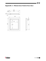
1
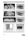
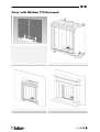
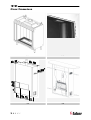
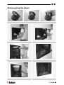
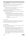
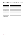
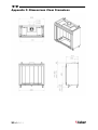
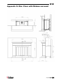
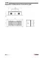
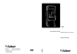
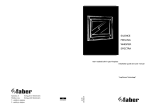
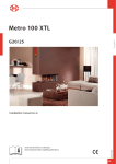
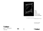
Clear 40010631 - 0811 UK Installation Guide IRL UK IRL Content 1.1 1.2 1.3 1.4 1.5 1.6 A C 1.7 1<<<< B D 1.8 UK IRL Clear with Wirdum 770 Surround 2.1 2.2 2.3 2.4 >>>>2 UK IRL Clear Frameless 3<<<< 3.1 3.2 3.3 3.4 UK IRL (De)mounting the Glass 4.1 4.2 4.3 4.4 4.5 4.6 4.7 >>>>4 UK IRL Content 1 Introduction ......................................................................................... 6 2 Safety and general information .................................................................. 7 3 Installation requirements ......................................................................... 8 4 5 3.1 Point of interest for the False chimney Brest ........................................... 8 3.2 Point of interest for the Wirdum 770 surround.......................................... 8 3.3 Flue requirements............................................................................ 9 3.4 Flue restrictor ................................................................................ 9 3.5 terminal position ............................................................................. 9 Instruction for Installation ....................................................................... 11 4.1 Gas Connection .............................................................................. 11 4.2 Preparing the appliance.................................................................... 11 4.3 Placing the appliance....................................................................... 11 4.4 False Chimney Brest without surround .................................................. 12 4.5 False chimney with surround .............................................................. 12 4.6 Removal of the glass........................................................................ 14 4.7 Placing the log set .......................................................................... 14 Commissioning (functional checks) ............................................................. 15 5.1 Pilot ignition check ......................................................................... 15 5.2 Check functional burner and pilot burner............................................... 15 6 Handing over (final check and customer briefing) ........................................... 16 7 Servicing ............................................................................................ 16 7.1 Routine anual servicing .................................................................... 16 7.2 Cleaning the glass ........................................................................... 16 7.3 Cleaning the combustion chamber and burner ......................................... 17 7.4 Cleaning the Surround ...................................................................... 17 Appendix A: Example calculation..................................................................... 18 Appendix B: Flue restrictor............................................................................ 19 Appendix C: Installation of the flue.................................................................. 20 Appendix D: Technical specifications Flatburner .................................................. 21 Appendix E: Technical specifications Logburner ................................................... 22 Appendix F: Dimensions Clear Frameless ........................................................... 23 Appendix G: Dim. Clear with Wirdum surround .................................................... 24 Appendix H: Dimensions Convection grid ........................................................... 25 Appendix J : Dimensions Control box door.......................................................... 26 5<<<< UK IRL 1 Introduction Note: these instructions should be read carefully and retained for future reference. Please leave these instructions with the user. This manual covers both models. Both are developed to be installed in 3 ways: • Frameless in an existing builders opening or false chimney breast • in combination with the Wirdum 770 surround Special features: • Room sealed appliance, inlet and outlet are led to the outside using a natural draught concentric pipe system (100 mm/150 mm) (no power fan required) • Air supply and flue-gases go to outside atmosphere through wall or roof. A maximum horizontal extension of 6 meters is possible • Remote Control standard on both models • Meets the requirements of the European Gas Appliance Directive (GAD) and carries the CE mark >>>>6 UK IRL 2 Safety and general information Before installation, ensure that the local distribution conditions (identification of the type of gas and pressure) and the adjustment of the appliance are compatible. This gas appliance is factory set and can not be adjusted. This appliance does not contain any component manufactured from asbestos or any asbestos related products. The pilot and flame sensing device fitted to this fire is also a safety device. If for any reason any part of the pilot assembly is to be replaced, the entire assembly, including the pilot burner, thermocouple, electrode and injector, must be exchanged complete for a pilot assembly from the original manufacturer only. Ventilation This appliance is room-sealed and doesn't require purpose provided ventilation. Never use the appliance if it has a broken glass. General safety It is the law in the UK that all gas appliances, are installed by a competent person in accordance with the Gas Safety (Installation and Use) Regulations (as amended), the relevant British Standards for Installation work, Building Regulations, Codes of Practice and the manufacturers instructions. Always use an additional guard if there are elderly, infirm or children in the same room of the appliance. The installation should also be carried out in accordance with the following where relevant: • BS5871 Part1 • BS5440 Parts 1 & 2 • BS1251 • Building Regulations Document J (as applicable) • Building Regulations and Standards issued as relevant by the Department of the Environment or the Scottish Development Department • In the Republic of Ireland installation should be carried out in accordance with IS813, ICP3, IS327, Building Regulations, Codes of Practice, the manufacturers instructions and all other regulations in force Failure to comply with the above could leave the installer liable to prosecution and invalidate the appliance warranty. 7<<<< UK IRL 3 Installation requirements Note: Since the appliance is a source of heat, circulation of air occurs. Therefore it is of importance that you do not use the appliance shortly after a renovation of the home. Due to the natural circulation of air, moist and volatile components from paint, building materials, carpet etc. will be attracted to the lit appliance. These components can settle onto cold surfaces in the form of soot. As on all heat producing appliances, soft furnishings such as blown vinyl wallpaper placed too near the appliance may become scorched or discoloured. This should be born in mind when installing the appliance. 3.1 Point of interest for the False chimney Brest The appliance can be installed in a new made hollow wall construction or in an existing builders opening. For the dimensions of the appliance, see appendix F & G In both cases keep the following in mind: • do not place the appliance on combustible materials or carpets • both walls have to be made of non-combustible material (e.g. Promatect) • do not place the lintel, surround or marble stone directly onto the appliance. If possible, apply a lintel made of cement or something similar • always ventilate the space above the appliance. Use the Faber ventilation grids delivered with the appliance • to avoid cracking, the plaster has to dry for at least 1 day per millimetre plaster • to avoid discolouring the plaster has to be heat resistant to min. 100 °C 3.2 Point of interest for the Wirdum 770 surround The Clear can be combined with the Wirdum 770 surround. Please keep in mind during build-up: • Let the appliance protrude 60 millimetre (see appendix G) • Adjust the appliance according the height of the floor plate and the filler pieces at the bottom • If the Clear is not build in an existing builders opening always ventilation grids must be placed (see appendix H) >>>>8 UK IRL 3.3 Flue requirements The appliance is of the type C11/C31. The appliance will need to be supplied with the approved Faber flue pipes and terminal, it is not possible to supply your own. The minimum effective height of the flue system must be 1 meter. Flue routing: • a horizontal extension with elbows is allowed for a maximum of 4 meters (Clear with flatburner) or 6 meter (Clear with logburner) • vertical max. 12 meters (without horizontal extensions only) Determine with the help of appendix A, B and C if the desired routing is possible. To establish this you will need to calculate: The effective height (this is the real difference in height between the upper side of the appliance and the terminal) The total horizontal extension. This is the total horizontal flue length where: 1. each 90-degree bend, which is in the horizontal area, counts for 2 meter 2. each 45-degree bend, which is in the horizontal area, counts for 1 meter 3. elbows and bends at the transition from horizontal to vertically are not to be counted 4. the wall mounted terminal counts for 1 meter 3.4 Flue restrictor If applicable, in the table of appendix B is also stated the size of a flue restrictor. This restrictor needs to be fitted in the combustion chamber when placing the appliance. Normally the smallest flue restrictor is fitted at production. 3.5 Terminal position Verify if the required terminal position meets the local installation regulations regarding disturbance, good functioning and ventilation: • The terminal must be located so that the outlet is not obstructed. If the flue terminal is located within 2 meters of a footway path or where people could come into contact with it, then a suitable terminal guard must be fitted • Terminals located close to shared walkways, footpaths etc. could be subject to legal constraints and this should be pointed out to the customer before installation. If in any doubt about flue location advice should be sought from local building control, or if appliance-related, from the manufacturer including wherever possible a dimensioned sketch 9<<<< UK • IRL Avoid locating the terminal in close proximity to plastic materials such as gutters or other combustibles. If this is unavoidable then a suitable deflector should be made. • Some important requirements for a good functioning are • The wall-mounted terminal has to be at least 0,5 m off: o Corners of the building o Below eaves o Balcony's etc. unless the duct is dragged to the front side of the overhanging part o The roof mounted terminal has to be at a distance of at least 0.5 meters of the sides of the roof, excluded the ridge > > > > 10 UK IRL 4 Instruction for Installation 4.1 Gas Connection Installation pipes should be in accordance with BS 6891. Pipe work from the meter to the appliance must be of adequate size. The complete installation including the meter must be tested for soundness and purged as described in the above code. A means of isolation must be provide in the supply to facilitate servicing. The connection should be made in 8 mm copper or similar semi flexible tube. (max 1 meter). Ensure that the gas pipe does not interfere with the removal or replacement of the burner tray or of the controls. The gas connection is nut and olive suitable for 8 mm pipe. 4.2 Preparing the appliance Remove the packaging and the pallet under the appliance. Adjust the total height of the appliance considering the way the appliance will be placed (see appendix H,J & K). For reasons of transportation the height is pre-adjusted to high. There are two ways to adjust the height: Rough adjustment: by removing the nut and bolt. Shift the leg 30mm and replace the nut and bolt 4.3 Fine adjustment: by adjusting the couple legs Placing the appliance Check paragraph 3.1 before commencing installation If possible, first place the appliance before assembling the flue Check if the floor and wall are sufficiently level and perpendicular. If not, you should fix this Prepare the gas connection, see paragraph 4.1 Position the firebox in the fireplace opening. Make sure that the appliance is level Fasten the appliance to the back wall using the four slideable positioning lips on top and on either side of the appliance Assemble the flue system onto the firebox (see appendix C) 11 < < < < UK 4.4 IRL False Chimney Brest without surround Build the false chimney using Promatect The measure in the clear of the false himney Brest has to be 770x782 (width x height). These sizes are including the finishing layers 4.5 Check regularly and before the finishing layer if the glass can be replaced False chimney with surround The heater can be installed in a range of positions in relation to the fireplace: • The appliance can be installed immediately behind the fireplace (e.g. Jellum Surround). In this case, the back of the surround is the front of the appliance • The appliance can be installed in the Surround (e.g. Wirdum Surround). In this case has appliance has to protrude 123 mm out of the wall 4.5.1 Preparation of the surround • When installing the natural stone fireplace, always make sure that the base is level (preferably, perfectly horizontal), clean and, above all, stable • Carefully remove the fireplace from the wooden crate in which it is delivered • Check that all the parts supplied in the crate are complete and undamaged. Lay them out in a safe place, so that you have a clear idea of what the various parts are • As far as possible, measure the dimensions using the drawing of the fireplace (see Appendix J or K) • Smooth the floor using a suitable screed. Be careful with limestone fireplaces, you may have to seal the hearth or lay plastic sheet underneath to reduce the risk of staining. Grey cement will stain the natural stone, use only white cement. When using Knauff (for example, to insert a plate), blistering may occur in some dark types of natural stone. An alternative is to apply a decelerator to the plaster • With a parquet floor, it is advisable to cut away the parquet to the size of the hearth, less 2 cm (left, right and front). If the parquet has not yet been fitted, you can place the hearth above it, so that the parquet can be fitted approximately 2 cm underneath • We recommend that you first conduct a 'dry run' of the fireplace assembly. Among other things, this will allow you to see how the various parts fit together • It is also recommended that you fit the fireplace first and then, if necessary, plaster around it • If necessary, smooth out the fireplace components using stainless steel washers > > > > 12 UK IRL 4.5.2 Assembly of the Surround • Establish the central point of the fireplace and mark this on the backing wall • Establish the distance between the appliance and the backing wall • If the backing wall is not level, you can fill it later • Lay the floor plate so that it is level in all directions (diagonal as well) • Install the appliance in terms of its heating function (see instructions supplied with the appliance) • Put the left- and right-hand uprights/sidepieces in position. These have already been glued together. They should fit on the left- and right-hand side of the hearth. The heater must be clear of the fireplace to allow for expansion and contraction with heat. Any gaps can be sealed with a ceramic rope or similar • Fill the space between the uprights and the backing wall with brickwork or Promatec, to allow further assembly. The uprights may be attached to this structure. The structure must also be able to absorb pressure at right angles onto the backing wall. We therefore recommend a brickwork structure • Saw the filler pieces to the right size. The size depends upon the way in which the hearth is fitted in relation to the fireplace • The components may be fastened together using acid-free silicone paste or twocomponent marble adhesive. Silicone paste takes longer to set, and so gives you more time to match the pieces exactly. It is also easier to remove (for example, using fishing line), if the pieces need to be disassembled • After this, you can fill the seams with the special coloured fitting kit • Check that all the connections are gas-tight and test the operation of the appliance • Add the finishing touches to the fireplace Note: Both the posts and the cap piece of the Jellum surround have to be mounted to the wall At both sides of the appliance there are two stop brackets for placing the legs of the surround Check the distance between the filler pieces to achieve a trouble free removal of the glass The drawer is to be mounted hand-tightened only with M6 bolts at the slider 13 < < < < UK 4.6 IRL Removal of the glass Two suction pads are delivered with the appliance to make removal easier. Always clean the suction lifters before use Remove the side panels (see figure 4.6) Remove the lower panel (see figure 4.5) Unscrew the cover panels on the left and the right (see figure 4.3) Remove the gasket (see figure 4.4) Place the suction lifters on the glass and bring the handles towards each other Lift the glass, move the lower part towards you and remove the glass downwards.. Replacing the glass happens in reversed order 4.7 Placing the log set In case of the Log burner: Place the log set as shown in the figure 1.1 In case of the Flatburner: Place the log set as shown in the figure 1.3 > > > > 14 UK IRL 5 Commissioning (functional checks) 5.1 Pilot ignition check • Ignite the pilot light as described in the user manual • Check if the pilot burner stays alight • Extinguish the pilot burner 5.2 Check functional burner and pilot burner The appliance is preset to give the correct heat input. No further adjustment is necessary. Always check the inlet pressure and burner pressure: • Turn off the gas valve on the appliance • Turn the inlet pressure test point C and apply the manometer • Check if the measured pressure is the same as the prescribed pressure • Perform this measuring when the appliance burns on full capacity and when only the pilot ignition burns • When the pressure is too low, check if the gas pipes are made of material with the right diameter • When the pressure is too high (more than 5 mBar overpressure) you can’t install the appliance and you should contact your gas company • Always check the burner pressure when the functional pressure is right • Open the burner pressure test point D • The pressure should match the described pressure. If this is not the case, then contact the supplier Note: After checking the burner pressure, the inlet pressure test point has to be shut and checked for gas-tightness. A B C 15 < < < < A. Governor B. Inlet pressure test point C. Burner pressure test point UK IRL 6 Handing over (final check and customer briefing) Instruct the customer on the full operation of the appliance and the remote control, including replacement of batteries Advise the customer how to clean the appliance including the glass Hand over these instructions including the user guide to the consumer Recommend that the appliance should be serviced by a competent person at least once a year 7 Servicing To ensure safe, efficient operation of the appliance, it is necessary to carry out routine servicing at regular intervals. It is recommended, that the fire is inspected/serviced by a competent person at least once a year. Important: Turn off the gas supply before commencing any servicing. Always test for gas soundness after refitting the appliance! 7.1 Routine anual servicing Clean (if necessary): a. the pilot system b. the burner c. the combustion chamber d. the glass Check the log layout and replace the embers (if applicable) Do the operating test as described in chapter 6 Check the flue system and terminal for damage and soundness (visual inspection) 7.2 Cleaning the glass Depending on the intensity of use, you can get material deposits on the glass. Remove the glass (see chapter 4.6). Remove the deposit with a special ceramic glass cleaner (ceramic hob cleaner) as follows: Remove the front and the back. Clean the glass. Handle the glass with clean hands, wear gloves if possible. To fit the glass, proceed in reverse order. Make sure that the log set has been installed correctly before fixing the glass. > > > > 16 UK IRL Attention: Before placing the glass: check the glass sealing rope is in good condition and makes an effective seal. Be sure that there are no fingerprints on the glass. It is not possible to remove those prints after you burn the appliance for a while (they are burnt in). Place the glass in front of the appliance and fix the glass frame or use the glass clamps. 7.3 Cleaning the combustion chamber and burner If the burner is visibly damaged, this can affect the distribution of the flame, if so then replace the burner: • Remove the front, glass, and log holder (if applicable) • Break the gas supply at the control valve. • Unscrew the burner assembly and take them out of the combustion • chamber. • Replace the burner assembly after cleaning 7.4 Cleaning the Surround • Clean the Surround using a dry non-scratch cloth or a vacuum cleaner. • Be careful! Do not use cleaning agents. The use of cleaning agents may cause discoloration of the stone. Also be careful when placing vases or flower pots on the fireplace. • If you do wish to use a cleaning agent, consult your retailer first. Your retailer can advise about special cleaners for natural stone. 17 < < < < UK IRL Appendix A: Example calculation Calculation 1: Calculating horizontal extension fig. 2a: Flue length C + E = 1m + 1m 2m Elbows D = 2m 2m Total horizontal extension 4m Measure or calculate effective height (Hvert) Flue length A 1m Roof mounted terminal 1m Total effective height 2m Always check if the calculated situation is allowed (see appendix B: Flue restrictor) Calculation 2: Calculation horizontal extension fig. 2b: Flue length J + L = 0,5 + 0,5 1m Elbows K + M = 2m + 2m 4m Terminal 1m Total horizontal extension 6m Calculation effective height (Hvert) Flue length H 1m Always check if the calculated situation is allowed (see appendix B: Flue restrictor) > > > > 18 UK IRL Appendix B: Flue restrictor Determine the right flue restrictor: • Calculate the total horizontal- and vertical length of the flue, according to the calculations in Appendix A • Determine according to the table the right flue restrictor size • When meeting an X, and when the values are outside the table, the combination is not allowed • Normally the 30 mm flue restrictor is pre-installed Horizontal length (m) Clear Flatburner 0 1 2 3 4 5 6 0 X X X X X X X 0,5 X X X X X X X 0 0 0 X X X X 0 0 0 0 X X X 2 30 0 0 0 0 X X 3 30 30 0 0 0 0 X 4 40 30 30 0 0 0 X 5 40 40 30 30 0 0 X 6 50 40 40 30 30 0 X 7 50 50 40 40 30 30 X 8 60 50 50 40 40 X X Real vertical height (m) 1 1,5 9 60 60 50 50 X X X 10 65 60 60 X X X X 11 65 65 X X X X X 12 65 X X X X X X Horizontal length (m) Clear Real vertical height (m) Logburner 19 < < < < 0 1 2 3 4 5 6 0 X X X X X X X 0,5 0 0 X X X X X 1 0 0 0 0 X X X 1,5 30 0 0 0 0 X X 2 30 30 0 0 0 0 0 3 40 30 30 0 0 0 0 4 40 40 30 30 0 0 0 5 50 40 40 30 30 0 0 6 50 50 40 40 30 30 0 7 50 50 50 40 40 X X 8 60 50 50 50 40 X X 9 60 60 50 50 X X X 10 65 60 60 X X X X 11 65 65 X X X X X 12 65 X X X X X X UK IRL Appendix C: Installation of the flue Connection with use of concentric duct material Make a hole of ø 153 mm for the wall or roof mounted terminal. The horizontal pipes need to rise away from the appliance at a rate of 3 degrees per metre Build the system starting from the appliance on. Make sure you place the pipes in the right direction, the narrow end towards the appliance Make sure the pipes are fixed sufficiently, a wall clamp every 2m, so the weight of the pipes is not resting onto the appliance. The outside of the pipe can become hot (140 degrees). Stay 50 mm away from wall surface or sealing. Make sure to provide sufficiently heat resistant isolation when going through the wall or roof. Because of expansion or cooling down the concentric pipes can turn loose. It is recommended to fix the spring clip with a self tapping screw at inaccessible places. To get the exact measure flue length you can use cut down concentric pipe, wall mounted terminal or roof mounted terminal. To obtain a smoke sealed connection, the inner pipe must be 20 mm longer then the outside pipe. > > > > 20 UK IRL Appendix D: Technical specifications Flatburner Country Flatburner Flatburner UK / IRL UK / IRL Cat II 2E+3+ II 2H3+ Appliancetype C11 of C31 C11 of C31 Reference gas G20 G31 8.8 7.6 2 2 Input (nett) kW Efficiency class Inlet pressure Mbar 20 37 Gas rate* l/h 925 350 Gas rate* gram/h Working pressure (high) Mbar 11.0 27.5 660 Injector size Mm Bray 900 Bray 280 Reduced input restraint Mm 2.10 1.30 Pilot assembly SIT 145 SIT 145 Code Nr.36 Nr.23 100-150 Flue system Flue size Mm 100-150 Std. Flue restrictor Mm 30 30 Gas control GV 60 C5E5M6M C5E5M6M Nut/olive 8 mm 8 mm Gas connection * at 15ºC and 1013 mbar 21 < < < < UK IRL Appendix E: Technical specifications Logburner Country Logburner Logburner UK / IRL UK / IRL Cat II 2E+3+ II 2H3+ Appliancetype C11 of C31 C11 of C31 Reference gas G20 G31 7.5 7.2 2 2 Input (nett) kW Efficiency class Inlet pressure mbar 20 37 Gas rate* l/h 790 293 Gas rate* gram/h Working pressure (high) mbar 11.5 29.6 550 Injector size mm 1.50 0.90 Reduced input restraint mm 1.80 1.10 Pilot assembly SIT 160 SIT 160 Code Nr.51 Nr.30 100-150 Flue system Flue size mm 100-150 Std. Flue restrictor mm 30 30 Gas control GV 36 C5AOEHC68M C5AODHC68M Nut/olive 8 mm 8 mm Connection * at 15º C and 1013 mbar > > > > 22 UK IRL Appendix F: Dimensions Clear Frameless 23 < < < < UK IRL Appendix G: Dim. Clear with Wirdum surround > > > > 24 UK IRL Appendix H :Dimensions Convection grid 25 < < < < UK IRL Appendix J : Dimensions Control box door > > > > 26 www.faber.nl – [email protected] Saturnus 8 NL - 8448 CC Heerenveen Postbus 219 NL - 8440 AE Heerenveen T. +31(0)513 656500 F. +31(0)513 656501 40010