1
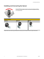
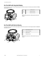
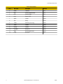
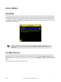
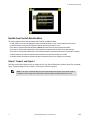
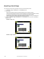
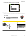
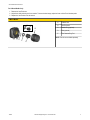
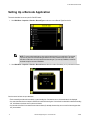
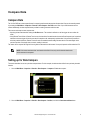
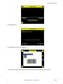
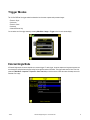
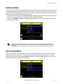
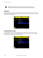
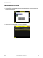
iVu Plus BCR Quick Start Guide
154722 9/7/2012
Rev. D
Contents
Contents
Introduction ............................................................................................................................................... 3
Installing and Connecting the Sensor ....................................................................................................4
iVu Plus BCR with Integrated Display
.................................................................................................................................5
iVu Plus BCR with Remote Display
.................................................................................................................................... 5
Sensor Modes
............................................................................................................................................7
Demo Mode ......................................................................................................................................................................... 7
Live Mode Overview ............................................................................................................................................................ 7
Read/No Read, Pass/Fail, Match/No Match ............................................................................................................... 8
Output 1, Output 2, and Output 3
...............................................................................................................................8
Acquiring a Good Image ...........................................................................................................................9
Setting Up a Barcode Application ......................................................................................................... 12
Compare Data .........................................................................................................................................13
Compare Data ................................................................................................................................................................... 13
Setting up for Data Compare ............................................................................................................................................. 13
Trigger Modes
......................................................................................................................................... 15
External-Single Mode ........................................................................................................................................................ 15
Continuous Mode ...............................................................................................................................................................16
External-Gated Mode
........................................................................................................................................................16
Command .......................................................................................................................................................................... 17
Industrial Ethernet Only
.................................................................................................................................................... 17
iVu Plus Communications Overview
Serial and Ethernet Output
Communication Channels
Multiple Inspections
....................................................................................................18
................................................................................................................................................ 18
.................................................................................................................................................19
...............................................................................................................................20
Adding a New Inspection
.................................................................................................................................................. 20
Changing Running Inspections
.........................................................................................................................................21
Changing Inspection Name or ID
......................................................................................................................................22
2
154722
Introduction
The iVu Plus BCR sensor is a barcode reader used to read a variety of barcodes and to optionally compare data to known values. The
sensor has an integrated color touch screen display or a remote display connection making installation, setup, and configuration easy
without requiring a PC.
Quick Start Overview
This guide is designed to provide the necessary information to get the iVu Plus
BCR up and running quickly. It provides an overview of the sensor and illustrates how to set up the sensor to read barcodes. The flow chart at left provides
an overview of the process.
Related Information
The following documentation is available on the Product CD:
•
•
•
•
•
•
•
iVU Plus BCR Datasheet
iVu Series Remote Display Datasheet
iVu Sensor Reference
iVu Plus BCR User's Manual
iVu Plus BCR Communications Guide
iVu Plus BCR with Remote Display Datasheet
iVu Plus BCR Integrated Datasheet
In addition, there is integrated Help built into the sensor itself.
NOTE: Before setting up the sensor, remove all
packaging. If using an iVu with an integrated touch
screen, carefully remove the plastic cover from the
sensor's touch screen display and put aside. You
should replace the cover after configuring the sensor to protect the display.
WARNING: Not To Be Used for Personnel Protection
Never use this product as a sensing device for personnel protection. Doing so could lead to serious injury or death. This product does NOT include the self-checking redundant circuitry necessary to
allow its use in personnel safety applications. A sensor failure or malfunction can cause either an energized or de-energized sensor output condition.
CAUTION: Electrostatic Discharge
Avoid the damage that electrostatic discharge (ESD) can cause to the Sensor.
Always use a proven method for preventing electrostatic discharge when installing a lens or attaching a
cable.
154722
www.bannerengineering.com - tel: 763-544-3164
3
iVu Plus BCR Quick Start Guide
Installing and Connecting the Sensor
The iVu Plus BCR sensor requires a bracket for mounting. Three brackets are available
from Banner. The brackets allow the sensor to be mounted either perpendicular to the part
or at an adjustable angle.
Available iVu Brackets
SMBIVURAL
SMBIVURAR
SMBIVUU
Thread three M4 x 4mm screws through the bracket into the mounting holes in the bottom of the sensor. Tighten all three screws.
4
www.bannerengineering.com - tel: 763-544-3164
154722
iVu Plus BCR Quick Start Guide
iVu Plus BCR with Integrated Display
The cable connections on the iVu Plus with integrated display are shown below, and power I/O connections (C) are defined in the Power
I/O Connections table below.
A
USB Connector
B
Ethernet Connector
C
Power I/O Connector
NOTE: Microlens model shown, C-Mount model connections are
identical.
C
A
B
iVu Plus BCR with Remote Display
The cable connections on the iVu Plus with remote display are shown below, and power I/O connections (B) are defined in the Power I/O
Connections table below.
A
Remote Display Connector
B
Power I/O Connector
C
USB Connector
D
Ethernet Connector
NOTE: Microlens model shown, C-Mount model connections are
identical.
B
A
C
154722
D
www.bannerengineering.com - tel: 763-544-3164
5
iVu Plus BCR Quick Start Guide
Power I/O Connections
Pin #
6
Wire Color
Description
Direction
2
Brown
10-30V dc
Input
7
Blue
Common (Signal Ground)
Input
6
Pink
External Trigger
Input
5
Gray
Remote Teach
Input
1
White
Output 1
Output
8
Red
Ready
Output
4
Yellow
Strobe Out (5V dc only)
Output
3
Green
Output 2
Output
9
Orange
Output 3
Output
10
Light Blue
RS-232 TX
Output
11
Black
RS-232 Signal Ground
Output
12
Violet
RS-232 Rx
Input
www.bannerengineering.com - tel: 763-544-3164
154722
Sensor Modes
Demo Mode
The first time you power up the iVu Plus BCR sensor, it starts in Demo Mode. Demo Mode uses stored images and inspection parameters that demonstrate how the sensor is set up without having to worry about focus, lighting, or triggers. In this mode, you can learn how
to make adjustments working with the sensor types while observing how the adjustments affect the sensor results. To exit Demo Mode,
go to Main Menu > System > Sensor Mode and select Exit Demo Mode. When you exit Demo Mode, the sensor reboots into its normal
operating mode with default settings.
NOTE: You may return to Demo Mode any time by going to Main Menu > System > Sensor Mode and selecting Demo.
Live Mode Overview
The iVu Plus BCR can be configured to evaluate one or more of the supported barcode types and can look for a specific number of
barcodes from 1 to 10. The barcode types are selected on the integrated touch screen by accessing Main Menu > Inspection > Barcode > Barcode Type . The barcode count is selected on the touch screen by going to Main Menu > Inspection > Barcode > Barcode
Count .
This section describes some general iVu Plus BCR concepts.
154722
www.bannerengineering.com - tel: 763-544-3164
7
iVu Plus BCR Quick Start Guide
Read/No Read, Pass/Fail, Match/No Match
The following describes what is meant by Read/No Read, Pass/Fail, and Match/No Match:
•
•
•
•
•
•
•
A Read condition occurs when the configured number of barcodes are found in a scan. These barcodes must be error-free.
A No Read condition occurs when the configured number of barcodes are not found in a scan.
If the sensor is configured where Data Compare is disabled, Pass and Fail are the same as Read and No Read.
If the sensor is using the Data Compare feature, Pass indicates that a good barcode was found and the data compared.
If the sensor is using the Data Compare feature, Fail indicates that either no good barcode was found or the data did not compare.
A Match condition occurs when the required number of barcodes are found and the compare is successful.
A No Match condition occurs when the required number of barcodes are found, but the compare is not successful.
Output 1, Output 2, and Output 3
The sensor has three output signals that you can configure for Pass, Fail, Read, No Read, Match, No Match, System Error, and Missed
Trigger. The default settings are Pass for Output 1, Fail for Output 2, and Pass for Output 3.
NOTE: For all outputs, the default setting is Latched, which means that the signal is active until the results of
an inspection cause a change in the signal output. If Pulsed is selected, the default pulse width is 50 ms.
8
www.bannerengineering.com - tel: 763-544-3164
154722
Acquiring a Good Image
The iVu Series sensor needs to capture a good image to ensure that it can read the barcode(s) correctly.
1. Go to Main Menu > Imager > Auto Exposure to run the Auto Exposure routine.
2. Check the lighting.
• Make sure that the lighting is constant and consistent (unchanging over time, no shadows or hot spots).
• Capture the barcode with lighting that optimizes its contrast and separates it from the background. Depending on the target,
this may mean the integral ring light is not the best choice and other Banner lights should be considered.
• Adjust the mounting angle to provide the clearest image of the barcode. The mounting bracket lets you easily position and
adjust the sensor on your line. Typically, a slight angle will help with read robustness.
3. If needed, go to Main Menu > Imager > Auto Exposure to run the Auto Exposure routine a second time or adjust Gain and
Exposure manually:
• Main Menu > Imager > Gain
• Main Menu > Imager > Exposure
154722
www.bannerengineering.com - tel: 763-544-3164
9
iVu Plus BCR Quick Start Guide
4. Go to Main Menu > Imager > Focus to adjust the focus while monitoring the Focus Number:
For Micro-lens Models Only:
1. Use the supplied 1/16" hex key to loosen the Focusing Window locking screw (D), then adjust focus on the iVu Series sensor using
the clear Focusing Window (B).
2. Adjust focus while monitoring the focus number. To ensure the best image, adjust the focus until
the Focus Number peaks.
NOTE: Turning the Focusing Window counter-clockwise focuses on
closer objects, while turning the Focusing Window clockwise focuses
on more distant objects.
3. Once the best image has been acquired, lock the focusing window.
Micro-Lens Models
A
Lens
B
Focusing Window
C
Locking Clip
D
Locking Screw
E
Filter Cap (optional)
F
Filter (optional)
NOTE: Filter Kits are available separately.
10
www.bannerengineering.com - tel: 763-544-3164
154722
iVu Plus BCR Quick Start Guide
For C-Mount Models Only:
1. Remove the Lens Enclosure
2. Adjust focus while monitoring the focus number. To ensure the best image, adjust the focus until the Focus Number peaks.
3. Replace the Lens Enclosure on the camera.
C-Mount Models
C
E
B
A
C-Mount Lens
B
Lens Enclosure
C
Retainer Ring (optional)
D
Filter (optional)
E
Filter Retainer Ring Tool
NOTE: Filter Kits are available separately.
D
154722
C
A
www.bannerengineering.com - tel: 763-544-3164
11
iVu Plus BCR Quick Start Guide
Setting Up a Barcode Application
This section describes how to set up the iVu Plus BCR sensor.
1. Go to Main Menu > Inspection > Barcode > Barcode Type to select one or more Barcode Types from the list.
NOTE: To ensure optimal performance, select only the barcode types for your application. For example,
if you use only one of the of the barcode types listed for All Linear, uncheck the box next to All Linear,
and select a radio button next to the desired linear barcode type. If you use only DataMatrix, uncheck all
the boxes except the one next to DataMatrix.
2. Go to Main Menu > Inspection > Barcode > Barcode Count to select the number of barcodes (1 to 10) to be read at one time.
Once the sensor has been set up as described:
• Each successfully read barcode is marked by a green bounding box. If annotations are on, the barcode data is also displayed.
• Any case where data does not compare is marked with a solid red bounding box. If the barcode is marked with a dotted red bounding
box, this indicates a checksum error or quiet zone violation.
• Any barcodes in the field of view that the sensor does not detect (for example, because they are not one of the barcode types selected), are unmarked.
12
www.bannerengineering.com - tel: 763-544-3164
154722
Compare Data
Compare Data
The iVu Plus BCR has a data compare feature for comparing read barcode data against reference data. Data can be manually entered
by accessing the Main Menu > Inspection > Barcode > Data Compare > Set Data screen. Data of up to 3200 characters can be
entered. Additionally, the data compare feature provides for masking characters within the data.
There are two other ways to enter compare data:
• Importing the last read data while viewing the Set Data screen. The new data is effective on the first trigger that occurs after this
action.
• Using Remote Teach. When a Remote Teach occurs, the data of the first read barcode is saved as Data Compare input. Inspections
executed on the next trigger will use the new data for comparison with subsequently read barcodes. If the previous input data contained any masked characters, Remote Teach will retain the masked characters only if the new data is of the same length as the
previous input data. If the length does not match, masking is removed.
The sensor tries to compare full length of this string with the data read from the barcode. If not equal, inspection will be marked as Fail.
NOTE: If the sensor reads more than one barcode in the field of view, only the first barcode data that the
sensor reads can be compared.
Setting up for Data Compare
This section describes how to set up the data compare feature. For this example, the reference data will be from a previously decoded
barcode.
1. Go to the Main Menu > Inspection > Barcode > Data Compare > Compare to Enable data compare.
2. Go to the Main Menu > Inspection > Barcode > Data Compare > Set Data , and click the Show last read data button.
154722
www.bannerengineering.com - tel: 763-544-3164
13
iVu Plus BCR Quick Start Guide
3. Press the Yes button.
4. Press the Home icon to return to the main screen.
For all subsequent triggers, when the sensor reads the barcode data, it will compare it against this reference data.
14
www.bannerengineering.com - tel: 763-544-3164
154722
Trigger Modes
The iVu Plus BCR has five trigger modes that determine how the sensor captures and processes images:
•
•
•
•
•
External - Single
Continuous
External - Gated
Command
Industrial Ethernet Only
You can select one of the trigger modes by accessing Main Menu > Imager > Trigger on the iVu touch screen display.
External-Single Mode
In External-Single mode, the sensor depends on an external trigger. For each trigger, the sensor captures an image and executes one
scan through the configured barcode types looking for the specified number of barcodes. This trigger mode uses the Scan Time Limit
parameter ( Main Menu > Inspection > Properties > Scan Time Limit ) to limit the amount of time the sensor will attempt to scan for
barcodes on an image.
154722
www.bannerengineering.com - tel: 763-544-3164
15
iVu Plus BCR Quick Start Guide
Continuous Mode
In Continuous mode, the sensor uses internal timing to continuously capture images. For each captured image, the sensor scans through
the configured barcode types looking for the specified number of barcodes. If the specified number of barcodes is found, a Read event
occurs. If the specified number of barcodes is not found, the sensor captures another image and repeats the scan. There are two parameters that are used to fine-tune how Continuous Scan mode operates:
• Same Code Reject Time (set at the bottom of Main Menu > Imager > Trigger )—time in seconds that must elapse before the scanner will report a previously scanned symbol again. A different symbol will be read immediately.
• Scan Time Limit ( Main Menu > Inspection > Properties > Scan Time Limit )—limits the amount of time the sensor will attempt to
scan for barcodes on an image.
NOTE: A No Read condition will not occur in Continuous mode as another image capture and scan automatically follows.
External-Gated Mode
External-Gated mode is similar to Continuous mode. While an external trigger input signal is active, the sensor continues to capture
images and run barcode scans until a successful Read occurs or the External Trigger input signal becomes inactive. The External Gated mode uses the Scan Time Limit parameter ( Main Menu > Inspection > Properties > Scan Time Limit ) to limit the amount of
time the sensor will attempt to decode barcodes on an image.
16
www.bannerengineering.com - tel: 763-544-3164
154722
iVu Plus BCR Quick Start Guide
NOTE: A No Read condition will not occur in External - Gated mode while the external trigger is active.
Command
In Command mode, the sensor will capture images when Trigger commands are received. The various trigger command modes described above can also be set through a command channel. Refer to Communications Chapter 6 for specific commands. The commands can
come from either Serial I/O or Ethernet I/O.
Industrial Ethernet Only
When Industrial Ethernet communication channel is enabled, triggers can be received from the modes mentioned above. Triggers
through Industrial Ethernet will not be executed if selected Trigger Mode is 'Continuous Scan'. If it is desired to receive triggers only
through Industrial Ethernet channel, select the 'Industrial Ethernet Only'.
154722
www.bannerengineering.com - tel: 763-544-3164
17
iVu Plus BCR Quick Start Guide
iVu Plus Communications Overview
Serial and Ethernet Output
The iVu Plus provides for communicating with other devices via Ethernet or a UART serial communications port (RS-232). In order to
establish an Ethernet connection to the sensor, the external device must be configured with the correct IP address and correct TCP port
to communicate. If planning to use the serial communications connection, port settings for baud rate, data bits, parity, and stop bits must
be configured on the iVu Plus to match the settings of the external device.
The iVu Plus BCR RS232 port or ethernet port can be used to output barcode data to other applications. To access the Data Export
screen, go to Main Menu > System > Communications > Data Export . The user can enable or disable this feature. When enabled:
• if the sensor is configured for either External-Single or External-Gated trigger modes, every trigger results in the transmission of output data (if the sensor does not successfully read a barcode, the output will be NO_READ).
• if the sensor is configured for Continuous trigger mode, the sensor will only transmit output barcode data upon a successful read.
To access the Serial Output screen, go to Main Menu > System > Communications > Serial I/O
When RS-232 serial output is enabled, the user can configure:
• Serial Port Settings (listed below)
• Type of Data to Export (listed below)
• Output Format (listed below)
To access the Ethernet Output screen, go to Main Menu > System > Communications > Ethernet I/O .
When ethernet output is enabled, the user can configure:
• IP Address, Port number, Subnet Mask, and Gateway
• Type of Data to Export (listed below)
• Output Format (listed below)
Type of Data to Export:
•
•
•
•
•
•
•
•
Pass/Fail Output
Inspection Name
Barcode Count
Data Length
Symbol Type
Barcode Data
Frame Number
Inspection Time (ms)
Serial Port Settings:
•
•
•
•
•
Baud Rates
Start Bits
Stop Bits
Data Bits
Parity Control
Output Format:
• Start String
• Delimiter
• End String
18
www.bannerengineering.com - tel: 763-544-3164
154722
iVu Plus BCR Quick Start Guide
Communication Channels
The iVu Plus BCR supports up to four communications channels. To access the channels, go to Main Menu > System > Communications .
• Command Channel — a bi-directional communication protocol that currently supports ASCII and enables other devices to remotely
control the iVu Plus sensor and access sensor results
• Industrial Ethernet — a bi-directional communication channel that allows the user to control the sensor and access sensor results
using Ethernet/IP, Modbus/TCP, or PCCC protocol
• Data Export — used to export selected inspection data to a remote device
• Image Export — used to export inspection images to a remote device
Data export and command channel can be configured for either Ethernet or Serial I/O (but not both); image export is only available over
Ethernet. The table below briefly summarizes valid communication channel configuration options.
Command Channels
Scenario #1
Scenario #2
Scenario #3
Ethernet
Serial I/O
Ethernet
Serial I/O
Ethernet
Serial I/O
Command Channel
Yes
No
No
Yes
Yes
No
Industrial Ethernet
Yes
No
Yes
No
Yes
No
Data Export
Yes
No
Yes
No
No
Yes
Image Export
Yes
No
Yes
No
Yes
No
154722
www.bannerengineering.com - tel: 763-544-3164
19
iVu Plus BCR Quick Start Guide
Multiple Inspections
The iVu Plus BCR supports multiple inspections that facilitate storing and controlling up to 30 inspections of different types of barcodes.
By default, Inspection 1 is crated with Data Matrix and Linear Barcodes enabled.
Adding a New Inspection
To add a new stored inspection:
1. Go Main Menu > Inspection > Stored Inspections and click Add New.
2. Select Rename to type a new name for the new inspection.
3. Click Done. The new inspection with automatically begin running.
20
www.bannerengineering.com - tel: 763-544-3164
154722
iVu Plus BCR Quick Start Guide
Changing Running Inspections
To change the running inspection:
1. From the Home screen, click the yellow button in the top center of the screen that displays the currently running inspection. This
will display all the stored inspections.
2. Select the inspection to start and click the Start Running button that appears below it.
154722
www.bannerengineering.com - tel: 763-544-3164
21
iVu Plus BCR Quick Start Guide
Changing Inspection Name or ID
To change the name or ID of an inspection go to Main Menu > Inspection > Stored Inspections > Set Name/ID. Select the inspection
from the list.
22
www.bannerengineering.com - tel: 763-544-3164
154722


![iVu Plus BCR Quick Start Guide [ 154722 ]](http://vs1.manualzilla.com/store/data/005993547_1-f3116733e8f794d590f924e47d0edfff-150x150.png)