1
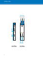
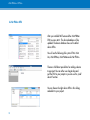
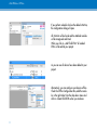
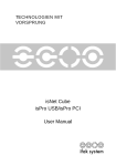
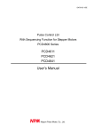
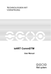
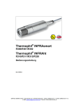
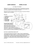
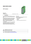
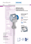
isNet DPMon & PAMon
Profibus Monitor Module
User manual
UNIFIED FIELD COMMUNICATION
isNet PAMon + DPMon
Content
isNet Line.................................................................. 3
1 isNet Lite................................................................ 4
1.1 Delivery Content.................................................. 5
1.2 Technical Data isNet Lite..........................................5
2 isNet PAMon and DPMon........................................ 6
2.1 Delivery content......................................................7
2.2 System requirements................................................7
2.3 Technical details isNet PAMon and DPMon................7
2.4 Configuration.........................................................8
3 Software Installation................................................ 9
3.1 Steps of Installation.................................................9
4 isNet PbMon DTM................................................. 10
5 The isField Diagnosis DTM..................................... 13
5.1 Online Status........................................................14
5.2 Online-Telegram-View...........................................15
5.3 Oscilloscope-Function............................................16
5.4 Statistics...............................................................17
5.5 Recording-Function...............................................18
5.6 Offline-Data-View.................................................19
5.7 Offline-Telegram-View...........................................20
6 Filter and Triggerevents.......................................... 21
7 Dimensional Drawing............................................ 22
2
isNet PAMon + DPMon
isNet Line
PROFIBUS DP
isNet DP2
isNet DP
isNet DPMon
isNet PA4
isNet PA2
isNet PAMon
PROFIBUS PA
isNet Lite
+
Foundation
Fieldbus
isNet FFMon
isNet PNGate
HART
isNet H@rt8
3
isNet H@rt4
isNet PAMon + DPMon
1 isNet Lite
The Ethernet-Gateway isNet Lite provides an efficient data exchange. Up to five fieldbusspecific modules can be connected, a free combination of PROFIBUS, FOUNDATION
FIELDBUS or HART modules is approved. The PROFIBUS modules are equipped with one
or two bus interfaces (single/dual module) and the HART modules are equipped with 4 or
8 HART-channels. The Ethernet port 100BASE-TX supports transfer rates of 10 Mbit/s and
100 Mbit/s.
Depending on the customer-specific needs the gateway can be supplied with up to five
PROFIBUS modules which results in a maximum of 10 PROFIBUS buses. Also the gateway
can be supplied with up to five HART modules, which results in a maximum of 40 HARTchannels. These HART channels can be used simultanously, because each HART channel
has its own HART master. It is also possible to connect up to five monitoring modules for
PROFIBUS PA, DP and FOUNDATION FIELDBUS.
The Ethernet-Gateway was developed for the use in an industrial environment. It needs a
24V power supply and will be mounted on a top-hat rail. The gateway and the fieldbus
specific modules are fanless and do not have any moving parts at all. They are built for a
long and enduring lifespan.
The isNet Lite is fully integrated in our driver concept of the fieldbus components isHART
and isDP . You can connect to the different networks through our API which is included
in the Driver-DLL. The applications which were designed for the HART- and PROFIBUSInterface (isHRT USB, isPro USBx12) can be used with the Ethernet-Gateway. A userfriendly
webinterface is implemented which can be used for the start-up. You can also use the webinterface to check the PROFIBUS modules and a connected network for its right function.
4
GND
24V
Shield
Power
Status
isNet Lite
Ethernet Gateway
isNet PAMon + DPMon
1.1 Delivery Content
Hardware, driver-, configuration-, test software on CD, documentation engl.
1.2 Technical Data isNet Lite
Technical Data
Interface
Controller
RAM
Flash
Transmission rate
Driver software
Available software
5
RJ 45 (Ethernet)
ARM9 32Bit 400 MHz
32 MB
256 MB
Ethernet: 10 Mbit/s – 100 Mbit/s
Windows 98, 2000, XP, Vista, 7
isNet CommDTM, isPro CommDTM (FDT), isPro Multi-
Server (OPC), OPC UA Server (FDI Communication Server)
isNet PAMon + DPMon
2 isNet PAMon and DPMon
With the isNet DPMon and isNet PAMon modules the head module isNet Lite can be
enhanced by new diagnosis and protocol monitor functions. The modules detects and
diagnoses sporadically occurring problems during data transmission on a Profibus network. The modules identifies configuration problems in the transmission protocol as well as
electrical faults that cause interruptions.
The DP monitor module offers one channel that can be connected to the Profibus network
via a D-SUB 9 connector. The PA monitor module offers two channels working independently from each other that can be connected to the Profibus network via screwtype
terminals.
Both monitor modules work totally passive; no telegrams are sent to the bus. The modules
evaluate the status of all stations on the bus and provide a concise overview about it if needed. In this view the bus status of every single layer of the OSI reference model is separately detected and can also be addressed separately.
The modules also offer a protocol monitor, an integrated 200 MHz oscilloscope and an
extensive analysis of statistical data, e.g. error counters or average time intervals. Long
term monitoring allows autonomous operation for a long period of time even if the Net Lite
is not connected to the PC. The protocol file is saved on a memory card and can later be
downloaded to a PC.
6
isNet PAMon + DPMon
2.1 Delivery content
isNet DPMon or PAMon, driver, configuration and testsoftware on the CD, documentation
english, isField Diagnosis DTM
2.2 System requirements
PC or Laptop with Windows 2000, XP, Vista or 7 32bit.
2.3 Technical details isNet PAMon and DPMon
Technical Data
Connectors
Measures
Transmission rate
Driver software
Delivery content
Available software
7
isNet DPMon
isNet PAMon
RS-485 Buchse
2 screw type terminals
22mm x 86mm x 110mm
45mm x 86mm x 110mm
9,6 kBit/s - 12 Mbit/s
31,25 kBit/s
Windows 2000, XP, Vista, 7
Hardware, Driver-, Configuration- and Testsoftware;
Documentation german and english on CD
isNet PbMon DTM, isField Diagnosis
isNet PAMon + DPMon
Channel 1 Channel 2
Shield Shield Shield
PA
- +
MMCSlot
PA
- +
MMC
RS-485
MMC
isNet DPMon
MMC
isNet PAMon
MMC- MMCSlot Ch1 Slot Ch2
isNet DPMon
8
isNet PAMon
isNet PAMon + DPMon
2.4 Configuration
3 Software Installation
You will find PACTware and the isNet PbMon DTM on the CD-ROM. The isField Diagnosis
DTM is a part of the isNet PbMon DTM. It is compatible to FDT 1.2.1.
3.1 Steps of Installation
1. PACTware 4.0
2. isNet PbMon DTM
isNet PbMon DTM
Driver Software
Version 1.0
© ifak system GmbH 2010 – 2011
Fieldbus Interfaces
9
Software Tools
Services & Technologies
Automation Components
isNet PAMon + DPMon
4 isNet PbMon DTM
After you installed PACTware and the isNet PBMon
DTM you can start it. The device database will be
updated. The device database shows all installed
device DTMs.
You will see the following ifak system DTMs: isNet
Lite, isNet DPMon, isNet PAMon and isNet FFMon.
There are 2 different possibilities for adding a device
to a project. You can either use drag & drop and
pull the DTM in your project or you can use the „Add
device“ function.
You can choose the right device DTM in this dialog
and add it to your project.
10
isNet PAMon + DPMon
If you perform a double click on the added isNet Lite,
the configuration dialog will open.
All isNet Lite will be found and the attached modules
will be recognised and listed.
When you click on „Add Child DTMs“ all needed
DTMs will be add to your project.
As you can see all devices have been added to your
project.
Alternatively, you can configure your devices offline.
Check the Offline Configuration Box, add the modules in the right order from the drop-down menu and
click on Create Child DTMs when you are done.
11
isNet PAMon + DPMon
Connect with the module.
If you right click on the connected monitoring module
you will see a list of different options. The Diagnosis
DTM will be started by choosing Dagnosis -> Diagnosis channel.
12
isNet PAMon + DPMon
5 The isField Diagnosis DTM
After starting the Diagnosis DTM you will see this
Dialog.
You will see 5 buttons.
Record, Online Data, Offline Data, Options and Exit.
By clicking the buttons you will get to the different
dialogs.
Design of the Software
Online-Data
Record
Start
Stop
Telegram
Statistic
TriggerEvent
Event log
Layer
Filter
Oscilloscope
GSD files
View
Download
Offline-Data
13
Definition:
Status function
Options
Close
This picture shows you the design of the isField Diagnosis DTM software.
isNet PAMon + DPMon
5.1 Online Status
This is the online data view. All PROFIBUS members
will be dispayed. Preceding PROFIBUS masters are
indicated by an „M“.
The color green indicates that erverything is within its
expected range. Yellow would show you a warning
and red would show you an alarm. You can define
different events for the colors red and yellow.
You can choose the different layers with the slider.
You can retrive the status information static or dynamically.
The double arrow is for dynamic update and
the single arrow for static update.
14
isNet PAMon + DPMon
5.2 Online-Telegram-View
If you choose the layer PHY you will only see this
columns: runing number, timestamp and data.
Layer DP shows the following columns: running
number, timestamp, source- and destination adaress,
service, PRM and data.
The layer APP shows these informations: running
number, timestamp, source- and destination address,
service address, PRM and data.
You can save the telegrams by clicking on the
record button.
You will reach the filter options by clicking on
the filter button.
If you click into the telegram windows it will stop to
update the new telegrams.
Activate the filter options with this button.
If active, the box is checked.
You can switch between hexadecimal and
decimal view with this button.
If you would like to get to the latest telegram
you have to click this button.
15
isNet PAMon + DPMon
5.3 Oscilloscope-Function
You see a oscilloscope which optical and faunctional
equals a hardware oscilloscope. It has integrated
message decoding, can detect bus faults and present
them in a statistical summary and arbitrary user
events be defined which can be stored in an event
log. You have option for time, level, trigger level.
As source you can select falling or raising edge,
filter (same functionality as described before) and
threshold value.
The oscilloscope has 2 modi: normal mode and single mode. The single mode gives you a snapshot of
a trigger event and the normal mode is like a normal
continuos oscilloscope.
The button force has the same functionality like the
button force on a hardware oscilloscope.
While you are using the oscilloscope, the telegrams
will be displayed and decoded under the graph and
in the windows right to the graph.
16
isNet PAMon + DPMon
5.4 Statistics
By clicking on the Statistics View, an overview of
different triggerevents and its values is shown.
You can change the Layer for which the statistics are
shown with the slider.
17
isNet PAMon + DPMon
5.5 Recording-Function
If you start a recording you can choose a file name
with 8.3 characters an a destination.
After you have typed the file name and clicked OK
the recording will start immediately.
The recording lasts as long as there is space on the
memory card, as long as no trigger event is reached
or as long as you do not stop it. The oscilloscope
has a memory depth of up to 1 mega samples (in
Singelshot mode).
You can load the file directly with in the isField Diagnosis DTM software or you can download it to your
PC and look at it later or send it to a specalist.
To display the recorded data you have to press the
button for the offline data in the start menu of the
isField Diagnosis DTM software.
18
isNet PAMon + DPMon
5.6 Offline-Data-View
You will see this dialog. You can open local files and
files from the MMC card.
If you want to open a file from the MMC card all files
on the card will be shown and you can select the one
you would like to open or to download to your PC.
You will get a similar view as you have seen in the
online telegram view.
19
isNet PAMon + DPMon
5.7 Offline-Telegram-View
In the offline view, you have the same options,
the same columns, the same filter menus as in
the live view.
20
isNet PAMon + DPMon
6 Filter and Triggerevents
For every layer, you can define Filter indepentendly. For each layer, only the appropriate filter variables are
shown.
21
isNet PAMon + DPMon
7 Dimensional Drawing
Dimensional drawing of 1 and 2 channel module.
© 2012-07
22
ifak system GmbH
Tel+49.391.544.563-1000
Oststr. 18
Fax+49.391.544.563-9099
39114 Magdeburg
[email protected]
Germany
www.ifak-system.de