1
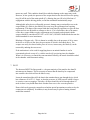
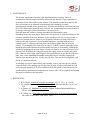
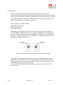
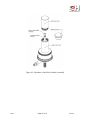
Wright Dust Feeder II
(WDF-II)
User’s Manual
Setup, Operation and Maintenance
(Version 3)
CH TECHNOLOGIES (USA), Inc.
© Copyright 2015
CONTENTS
1. Preface………………………………..………………….……….……………..…. 3
2. Introduction………………………………………………………………………... 3
3. Assembly Instructions…….…………………………………………….…………. 3
4. Operating Instructions……………………………………………………………... 4
5. Compressed Air……………………………………………………………………
8
6. Breakdowns……………………………………………………………………….. 8
7. Dust………………………………………………………………………………... 9
8. Maintenance……………………………………………………………………….. 10
9. References...……………………………………………………………………….. 10
10. Appendix 1…………..…………………………………………………………… 12
11. Appendix 2………..……………………………………………………………… 14
12. Revisions…………………………………………………………………………. 15
WDF-II
Page 2 of 14
7/21/2015
1. PREFACE
The Wright Dust Feeder has been available to research scientists for almost 60 years,
since its development by Martin Wright. A number of improvements and upgrades were
introduced by BGI, Inc., in the current model WDF-II. BGI's contribution to the
technology has been the standardization of stainless steel parts, the small and mini dust
chamber, the development of the Venturi outlet for superior de-agglomeration, the
variable speed motor and the development of the carbide cutter head. Because carbide is so
long wearing and superior to the stainless steel blades they are now furnished as standard.
Stainless steel heads and blades are only available as replacement parts.
CH Technologies (USA), as the new owner of the Wright Dust Feeder product line,
is committed to maintain and further the quality standards established by the
original developer, BGI. We do this by maintaining the standard gages developed by
BGI to ensure parts interchangeability among the thousands of Wright Dust Feeders, both
Mark 1 and Mark II, currently in service.
2. INTRODUCTION
The Wright Dust Feeder, Mark-II (WDF-II) has been designed to provide uniform, airborne
concentrations of dust for long periods of time. As with all aerosol generation equipment,
not all materials are suitable for use with the mechanism. If there is a question which
cannot be answered in the literature, consultation with the manufacturer is suggested.
All component parts of the instrument in contact with the dust are fabricated from stainless
steel. Considering unit density materials, the instrument has a feed rate ranging from 8
milligrams to 63 grams per hour. With the optional Mini chamber assembly (DF 300), the
range may be extended down to 2.6 milligrams per hour.
3. ASSEMBLY INSTRUCTIONS
The instrument is furnished with a large (A) and small dust chamber. There is a
corresponding large (K) and small scraper head. The instrument is shipped with the large
components installed. If it is desired to commence operations with the small scraper and
dust chamber the large components must first be removed.
First pull up the long pinion (C) so as to disengage pinion (E) from gear (D). Cup (A)
should then be unscrewed from cap (B) along with the scraper head (K). The corresponding
small parts may then be assembled in reversed order. See Figure 1 for illustrations.
WDF-II
Page 3 of 14
7/21/2015
4. OPERATING INSTRUCTIONS
4.1. Before starting operation the concentration of dust to be created must first be chosen.
Once this had been done the initial operating conditions may be calculated with reference
to Table 1. This is conveniently illustrated by example:
Desired Concentration:
System Flow Rate:
Density of Dust:
10 mg/m3
3 m3/min
2 g/cm3
Feed Rate (g/min.) = conc. (mg/m3) x Flow Rate (m3/min.) = 10 x 10-3 g/m3 x 3 m3/min. =
0.03 g/min. = 1.8 g/hr.
Dividing by the density yields the required volume of dust per hour.
V = Feed Rate (g/hr)/Density (g/cm3) = 1.8 g/hr/2g/cm3 =0.9 cm3/hr.
Referring to Table 1, this feed rate may be achieved with the large chamber at
approximately 0.07 rpm or with the small chamber at 0.6 rpm.
Figure 1. Historical Drawing from the Original Publication
WDF-II
Page 4 of 14
7/21/2015
Figure 2. Typical Flow Rate vs. Air Pressure Curve
WDF-II
Page 5 of 14
7/21/2015
Table 1. Volume of Dust Displaced, cm3/hr
Lg.
RPM
0.1749
6
62.96
5
52.47
4
41.98
3
31.48
2
20.99
1
10.49
0.9
9.44
0.8
8.40
0.7
7.35
0.6
6.30
0.5
5.25
0.4
4.20
0.3
3.15
0.2
2.10
0.1
1.05
0.09
0.94
0.08
0.84
0.07
0.73
0.06
0.63
0.05
0.52
0.04
0.42
0.03
0.31
0.02
0.21
0.01
0.10
0.009
0.09
0.008
0.08
0.007
0.07
0.006
0.06
Sm.
Mini
0.0219
7.88
6.57
5.26
3.94
2.63
1.31
1.18
1.05
0.92
0.79
0.66
0.53
0.39
0.26
0.13
0.12
0.11
0.09
0.08
0.07
0.05
0.04
0.03
0.013
0.012
0.011
0.009
0.008
0.0073
2.62
2.18
1.75
1.31
0.87
0.44
0.39
0.35
0.31
0.26
0.22
0.17
0.13
0.087
0.044
0.039
0.035
0.031
0.026
0.022
0.017
0.013
0.0087
0.0044
0.0039
0.0035
0.0031
0.0026
The large chamber has a working capacity of 40 cm3 and the small, 5 cm3.
Running Time = chamber volume (cm3)/req. Volume/hr (cm3/hr)
= 40 cm3 /0.9 cm3 /hr = 44.4 hrs - large chamber
= 5 cm 3 /0.9 cm 3 /hr =5.6 hrs - small chamber
= 1.3 cm3/0.9 cm3/hr =1.44 hrs - mini chamber
The actual rate of feed to produce a concentration is subject to many variables, including
the properties of the dust and the system into which it is fed. However, once an initial
experiment has been performed, it is a simple matter to calculate, by proportion, a new
rotational speed to achieve the desired amount.
WDF-II
Page 6 of 14
7/21/2015
4.2. To fill the container, pour the dust in a little at a time (say, 1/8 in layer), ramming it
down with the rammer after each addition. The ramming should be done vigorously and it
will then be found that the dust packs to a consistent density which is usually about half
of the material of which it is composed, although this is much affected by the fineness of
the dust. Consistency is what is sought. The equipment details are to be user supplied.
For dusts which pack consistently with hand pressure, a bathroom or shipping room scale
may be placed on the work surface and each compression taken to a standard "weight".
The best all-round packing device is "2 Ton Arbor Press" which can be obtained from
any machinery supply company. If this device is not available outside the USA, seek a
"Fly Press".
Should even higher pressures be required a hydraulic press may be utilized.
The dust can be packed to within 8 mm, of the mouth of the container, giving a
maximum working distance of 36 mm. The effective volume of the large container is
approximately 40 cm3, reduced to 5 cm3, when the small container is fitted. The mini
container volume is about 1.3 cm3 '
4.3. Having packed the container, screw the cap (B) up to the top of the threaded spindle (F)
as far as it will go, and then screw the container (A) into the cap. Care must be taken not to
overfill the container or it will not be possible to screw it into position. Screw the
container down gently until a slight resistance is felt, indicating that the scraper head
(K) is in contact with the dust. Push down the pinion C so as to engage the small
pinion (E) with the gear (D). The mechanism is then ready to operate.
4.4. Dusts which contain many fibers, e.g. cotton fibers from a new bag filter, are difficult
to use for long periods as the fibers accumulate in the scraper and eventually clog it.
Sometimes the fibers can be removed from the dust by cleaning it but if this is liable to
affect its properties, a fresh sample must be obtained.
4.5. To actually operate the dust feeder plug the control module into a suitable power source.
Connect the control cable from the module to the dust feeder. (The couplings are arranged
so that assembly is obvious.) Activate the switch on the back of the power module and the
speed display will illuminate. The rotational speed can be controlled by rotating the
speed control knob on the front panel.
The current model speed control will operate on 120 V / 60 Hz or 240 V /5 0 Hz.
Switching is internal and automatic. Because of the diversity of plugs used throughout
the world, all models are supplied with a U.S. style plug. The may either be cut off and
replaced or a user supplied adaptor fitted.
WDF-II
Page 7 of 14
7/21/2015
5. COMPRESSED AIR
5.1. The quality of the compressed air used is probably the most important factor in the
performance of the mechanism. Fine dust is easily rendered undispersable by either
water or oil.
Excess moisture can be removed from the air either by means of the usual desiccants,
e.g. silica gel, or by cooling the air to below room temperature while under pressure.
Most rotary or piston type compressors deliver a fair amount of oil with the air, in the
form of a very fine aerosol which will pass most commercial filters and travel along a
considerable length of piping. This tends to be absorbed by the dust in the tube and
eventually clogs the mechanism. It can be filtered out with ordinary filter paper, which
will last as long as it is not sodden with oil. It is better, however, to use a completely dry
oil-less compressor or, for short runs, a cylinder or compressed air.
5.2. The air pressure utilized should never be less than 8 psig. This pressure will assure
sonic velocity in the outlet nozzle and complete breakup of agglomerates. Lower
pressures are certain to cause plugging of the outlet and/or the occurrence of large
clumps being emitted. Eight psig is approximately 15-20 1pm air flow. If a larger
volume of air is required the jet may be drilled out. It is unadvisable to utilize air
pressures higher than 25 psig or high velocity disruption of the compressed particulate
cake may occur. A typical Flow Rate vs. Pressure curve is shown in Figure 2.
6. BREAKDOWNS
Apart from electrical and air supply failures, two types of breakdowns may occur. In
both cases the result is cessation or reduction of the air flow, followed by a stoppage of the
mechanism. It is essential to realize that a mechanical stoppage is always secondary, the
power required to scrape up the dust when an adequate stream of air is passing through
the mechanism is very small and well within the capacity of the motor.
It can be tested by connecting to a suitable compressed air supply, as described below, and
then disengaging the driving gear and rotating by hand. A visible cloud should emerge
while the mechanism is being rotated and should cease as soon as it is stopped. If a
cloud emerges when the container is not being rotated, the dust has not been packed
tightly enough, or else it is too coarse to be suitable.
The mechanism should run without attention until the container is empty, when the
teeth on the cap (B) will travel beyond the pinion (C) so that although the container
continues to rotate it is no longer being fed down and there is no danger of damage from
overloading. If a blockage occurs for any reason when the mechanism is running, the
WDF-II
Page 8 of 14
7/21/2015
motor may stall. This condition should be avoided as damage to the motor may result.
However, at low speeds, the pressure of the scraper head on the dust will force the spring
ring (N) off the end of the main spindle (G), allowing the gear (D) to be lifted out of
engagement with the driving pinion, so that the mechanism automatically stops.
Although this safety device will usually prevent it, damage may occasionally occur to the
scraper blade (0), which is also liable to be worn away after prolonged use requiring
replacement. The shape of the scraper blade has been found by experience to give the best
results and it is not advisable to attempt to alter is. If it is found that, due to the nature
of the dust, scraper blades require replacement too frequently and optional carbide
scraper should be considered (DF 193C or DF 194C). In 2006 Carbide blades became the
default standard for new instruments.
Blockage of Scraper only - This is almost in variably due to the presence of oil or water
in the air or of fibers in the dust, the prevention of which is described above. The
scraper can easily be cleared with a piece of wire or, in necessary, the blade (0) can be
removed by undoing the two screws.
If the mechanism is to be used for supplying dust to an animal chamber it can be
conveniently placed on top of it, with the nozzle (Q) projecting into the chamber.
When it is necessary to control the concentration accurately, the nozzle should be sealed
in the chamber with elastomeric tubing.
7. DUST
The dust used MUST be fine ground i.e., the great majority of the particles less than 20
micrometers in diameter. This is necessary to ensure that the dust may be compressed
into a stable cake which will not be blown away.
It must be remembered that ALL the dust in the container has to pass through the jet, which
has a diameter of 0.052" (1.3mm), so that the presence of ONE particle which is larger
is certain to cause a stoppage. Therefore, all dusts should be sieved through about 60
mesh is there is any doubt about their freedom from even a few oversize particles.
Dusts which are hygroscopic cannot be used unless special precautions are taken to dry the
compresses air completely. In addition, it may be necessary to place a heating element
around the container.
WDF-II
Page 9 of 14
7/21/2015
8. MAINTENANCE
The primary maintenance function, other than lubrication is cleaning. Under no
circumstances should compressed air be utilized for this function. Larger quantities of
irritating or Toxic dust could become airborne. The desirable method is to immerse the
dust covered parts to be cleansed in an ultrasonic bath containing a wetting
agent/detergent suitable for the specific dust. This function should be carried out in a fume
hood. The cleaned parts should be air/oven dried. It is worth noting that as long as there is
no change in the type of dust utilized there is no necessity to
clean the apparatus, unless it is being dissembled for lubrication or repair.
Depending on the dust used and its abrasiveness it is necessary to clean and relubricate the
two main spindles of the unit. Because of the variables involved, it is not possible to
predict an accurate interval. However, too frequently will cause no harm, whereas too
seldom will result in excessive wear of spindles and gears, requiring replacement of
expensive parts. To lubricate, the long pinion gear and its spindle must be removed
entirely. To accomplish this, remove the hex nut (5/16 BSF) from the underside of the
mounting plate and withdraw the pinion spindle and gear as an assembly. Holding the
spindle by its hexagonal section, with a screwdriver unscrew the slotted fastener at the
opposite end. Withdraw the long pinion and thoroughly clean the spindle and pinion
bore. Lubricate with a light smear of grease and reassemble but do not install on the base
plate. Note, when reinstalling the spindle in the pinion bore to carefully compress the
friction rings into their grooves, as they enter the bore. This may be accomplished with
the tip of a small screwdriver.
To similarly service the adjacent dust cup assembly, remove, the dust cup (A), and the
scraper head (K). The retaining clip (N) may then be pried off which will permit the lead
screw and gear assembly (F,D) to be withdrawn from the spindle. Clean and grease the
spindle and bore and install all components in reverse order. The long pinion and spindle
may now be rebolted to the base plate.
9. REFERENCES
1. B.M. Wright, Journal of Scientific Instruments, Vol. 27, No. 1, p. 12,1950.
2. P.L. Magill, et. al. eds., Air Pollution Handbook, McGraw-Hill Inc., New York,
1956.
3. R. Dennis, ed., Handbook on Aerosols, National Technical Information Service,
TID No. 26608, 1976.
4. K. Willeke, ed., Generation of Aerosols and Facilities for Exposure Experiments,
Ann Arbor Science Publ., Ann Arbor, 1980.
WDF-II
Page 10 of 14
7/21/2015
10. APPENDIX 1
In 2006 a mini chamber was added to the specification in order to achieve lower
concentrations required with various kinds of exposure equipment and for devices simulating
environmental concentrations. This new attachment reduces the feed rate from the output
of the small chamber by a factor of 3 whilst providing the expected steady output. The
Mini chamber (DF 300) is an assembly comprising:
DF 198C Mini Cutter Head – carbide
DF 200 SS Mini Dust Cup
DF 197 Extension rod.
DF201 Mini Rammer
Additionally, your small dust cup must be of the most recent type with a removable end
cap. (DF183BSS). Additionally, the lead screw spigot assembly (SA176SS) must be the
rigid type. This type, which has been in production for several years, can be identified by
looking for a square internal reinforce, as seen from above. The difference between the old
and new type is illustrated in Figure Al.
Figure A1. Visual Difference Between Old and New Lead Screw Spigot
To assemble: Unscrew small dust cup from the container mount and remove the end cap.
Install (screw) the extension rod (DF197) and Mini Cutter head (DF198C) onto the Lead
Screw spigot assy. (SA176). Use the mini rammer (DF201) to pack the Mini Dust Cup as
described for the Large and Small Dust Cups.
Screw the Packed Mini Cup onto the Small Dust Cup and operate the WDF-II in the
normal manner.
WDF-II
Page 11 of 14
7/21/2015
Figure A2. Schematic of the Mini Chamber Assembly
WDF-II
Page 12 of 14
7/21/2015
11. APPENDIX 2
Technical Specifications:
Dust Feeder
Maximum Width: 4.75 in. (12.06 cm.)
Maximum Base Length: 5.25 in. (13.34 cm.)
Maximum 0/A Length: 10 in. (25.4 cm.)
Height 0/A: 7 in. (17.78 cm.) Weight: 41b, 15 oz. (2.24 Kg.)
Electronic Module
Width: 10.25 in. (26.04 cm.)
Depth: 6 in. (15.24 cm.)
Height: 3.5 in. (8.89 cm.)
Weight: 4lbs, 1 oz. (1.84
Kg.)
Electrical requirements:
120-240 VAC, 50-60 Hz Fuses: 0.5 amp
Pneumatic requirements:
2-20 P.S.I.G., 10-35 1pm
Environmental Operating Conditions:
Temperature: 0-40 C (32-104 F)
Altitude: Sea level – 6500 ft. (1981m) Relative Humidity: 0-100% non condensing.
Safety:
The WDF II is a test apparatus whose sole purpose is the generation of dry dust
concentrations. It is designed and intended to be operated by skilled professionals
whose background and training qualify them to do so. Every effort has been made
to ensure electrical and mechanical safety. Use and operation in excess of technical
specifications can lead to injury or death.
The electrical module is intended for use in dry environments. Care must be taken to
position it so that access to the on/off switch, which is located on the back of the
electronic module, is not obstructed.
Installation:
The WDF-II is intended to generate concentrations of dusts which may be hazardous or
toxic in nature. The chief facilities using this equipment are engaged in either filter testing
or toxic exposure studies. All personnel must be under the direct supervision of a
safety/occupational health professional. Unskilled operation can cause injury. The
equipment may be installed in any orientation as there is no restriction in this regard.
All safety guards must be in place during operation. No electrical grounding/earthing
provisions may be disconnected. The electrical cord used must be of an earthing type.
WDF-II
Page 13 of 14
7/21/2015
Regulating body:
There is no organization which has direct jurisdiction over the instillation and use of
Aerosol Generation equipment. However, there may be jurisdictions imposed by the
safety regulations of the organization using the equipment or the organization for
which tests are being performed.
12. REVISIONS
Rev 2 - Released 9/06 — Added mini chamber, updated Dust Displaced chart.
Rev 2.1- Released 12/06 — Added material required by CE Auditor.
Rev 3 – released 06/2015 – Reflects assumption of ownership by CH Technologies
WDF-II
Page 14 of 14
7/21/2015