1
USER’S MANUAL
AT Command Set Option V1.0
for µ-blox GPS Receiver Modules
GPS.G1-X-00001, October 27, 2000
For most current data sheets, please visit www.u-blox.com
µ-blox ag
Zürcherstrasse 68
CH-8800 Thalwil
Switzerland
Phone +41 1 722 7444
Fax +41 1 722 7447
http://www.u-blox.com
GPS Receiver with integrated GSM Control Software
We reserve all rights in this document and in the information contained therein. Reproduction, use or disclosure to third parties without express authority is strictly forbidden.
GPS.G1-X-00001
© 2000 µ-blox ag
Page 1
AT Command Set Option User’s Manual
µ-blox ag
CONTENTS
1
Features........................................................................................................................ 4
2
Overview...................................................................................................................... 5
3
Functionality of the AT Firmware............................................................................... 6
3.1
Triggers and Events ......................................................................................................................... 6
3.2
Actions ........................................................................................................................................... 6
3.2.1
Data SMS................................................................................................................................. 6
3.2.2
Data Call.................................................................................................................................. 6
3.2.3
Voice Call................................................................................................................................. 7
3.2.4
RX ........................................................................................................................................... 7
3.2.5
Answering calls ........................................................................................................................ 7
3.3
Data SMS........................................................................................................................................ 7
3.4
Configuration.................................................................................................................................. 8
3.4.1
General Settings ....................................................................................................................... 8
3.4.2
GSM Modem Specific Settings................................................................................................... 9
3.5
Protocols......................................................................................................................................... 9
3.5.1
Configuration Protocol.............................................................................................................. 9
3.5.2
AT-Firmware - Modem............................................................................................................ 14
3.5.3
Host protocol ......................................................................................................................... 14
3.6
Special Function Pins...................................................................................................................... 18
3.6.1
Power on/off Signal ................................................................................................................ 18
3.6.2
4
Reset Signal............................................................................................................................ 18
Supported GSM modems .......................................................................................... 19
4.1
How to set up your modem ........................................................................................................... 19
4.2
Recommended schematics and settings .......................................................................................... 19
4.2.1
Connection to the modem...................................................................................................... 20
5
µ-Tracker – Demo Program for the GPS-MS1E-AT ................................................... 21
5.1
Views............................................................................................................................................ 21
5.1.1
SiRF console ........................................................................................................................... 21
5.1.2
AT console ............................................................................................................................. 21
5.1.3
Map view............................................................................................................................... 22
5.2
6
Settings Dialog .............................................................................................................................. 22
Configuration examples............................................................................................ 24
6.1
Tracking an object with a position update via SMS every 1 minute ................................................... 24
6.2
Tracking an object with a position update via SMS every 500m........................................................ 24
GPS.G1-X-00001-P1
Page 2
AT Command Set Option User’s Manual
µ-blox ag
6.3
Send a position and an identification string if a button is pressed ..................................................... 24
6.4
Voice connection and position via SMS if a button is pressed ........................................................... 24
6.5
Online tracking if a certain area is entered ...................................................................................... 24
7
Limitations ................................................................................................................. 26
A
Used AT Commands .................................................................................................. 27
B
Type definitions......................................................................................................... 28
C
Related Documents.................................................................................................... 32
D
Glossary ..................................................................................................................... 33
E
Contact ....................................................................................................................... 34
Revision History............................................................................................................... 35
GPS.G1-X-00001-P1
Page 3
AT Command Set Option User’s Manual
µ-blox ag
1 FEATURES
§
SW Enhancement for the µ-blox GPS-MS1E and GPS-PS1E
-
Fully compatible to standard µ-blox GPS receivers
-
Configuration through the serial interface
-
Designed for autonomous operation
-
Minimal external circuitry and no external controller required
§
Supports a sub-set of the AT command set for the control of GSM modems
§
SMS messages, data connections and voice calls autonomously triggered by GPS or external events.
§
Various configurable trigger
§
-
Timer
-
Movement
-
Area
-
Digital IO
-
External events
External requirements:
-
power supply for GPS and GSM
-
Backup battery for real time clock and SRAM
-
Serial interface for NMEA or SiRF binary data
-
Passive or active Antenna
-
GSM Modem supporting AT Interface (GSM 07.05, 07.07)
GPS.G1-X-00001-P1
Page 4
AT Command Set Option User’s Manual
µ-blox ag
2 OVERVIEW
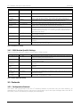
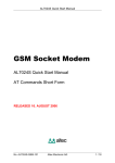
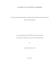
A typical application for Fleetmanagement, AVL or Tracking requires position information and communication
with a central office. The traditional setup requires a GPS receiver, a GSM modem and an external controller.
This controller reads positions from the GPS receiver and controls the modem. Incorporating the control of the
GSM modem into a GPS receiver spares the extra processor, which simplifies the design and saves cost.
With the AT command interface for GPS receivers µ-blox offers an integrated control system for GSM modems.
This control system is designed for autonomous operation. An external controller is not required but can be used
for enhanced functionality.
An external controller may communicate with the GPS receiver via a serial port with the SiRF binary protocol. The
GSM modem is connected to the other serial port and is controlled through the GPS receiver. Minimal external
wiring is necessary to get a fully functional system to send position information via GSM (SMS, data connection).
SMS
Data
packets
Serial
Port 0
AT commands
GSM
Power
ON/OFF
GSM Controller
Wakeup GSM
Serial
Port 1
SiRF Binary Protocol
External
Controller
General
Purpose IOs
GPS
GPS-MS1E-AT
GSM Modem
AT Command
Figure 1: Schematic
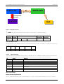
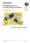
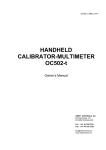
The GSM controller is event driven. For each event an action and the data transmitted can be defined. Events
(triggers) may be the output of the GPS engine (position, time) or an external signal. If the conditions for a
trigger are met, the assigned action will be performed. This assignment is set during the configuration of the
GSM controller.
Events
Triggers
GPS Output
GPIO
Triggers
Actions
Call stack
Call
SMS stack
Send SM
Events
Figure 2: Triggers and Actions
This document describes the commands and protocols used for the configuration and control of the AT
command firmware (See Chapter 3.5), the possible functions of the firmware and the data transmitted (See
chapter 3). In order to provide an easy and fast possibility to configure the module we offer the µTracker PC
software, available from our WWW Pages.
The GPS-MS1E and GPS-PS1E with the AT option will be referred to as GPS-MS1E-AT and GPS-PS1E-AT
respectively.
GPS.G1-X-00001-P1
Page 5
AT Command Set Option User’s Manual
µ-blox ag
3 FUNCTIONALITY OF THE AT FIRMWARE
3.1 Triggers and Events
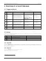
A trigger is assigned to each event. Table 1 contains all triggers with their parameters:
ID
01
02
Event/Trigger
Condition
Parameters
Range
Timer (2x)
Time interval elapsed.
Interval [s]
30 – 2 600 000s
Area
Latitude 1, Latitude 2,
Longitude 1, Longitude 2,
Inside/Outside,
Repetition time [s]
Note: Lat1 > Lat2 and
Lon1 > Lon2
-180 – 180°
-90 – 90°
03
The position is either in or
outside a spherical rectangle.
The trigger is repeated if the
position remains in/outside.
04
Movement
Distance [m]
0 – 320000m
05
Speed
Velocity [m/s]
Repetition time [s]
1 – 500m/s
0 – 2 600 000s
07
08
09
10
1
The distance to the last position
is above the adjusted value.
The velocity is above the
adjusted value. The trigger is
repeated if speed remains
above the adjusted value.
0 - 2 600 000s
GPIO (2x)
High level for at least 1 second.
GPIO number
0 - 11
External
SiRF protocol message.
Is generated if a SMS request is
sent.
None
-
None
-
Internal
Table 1: Events
3.2 Actions
Action can be assigned to the different events. Any Action consists of one out of four possible phone number
and the data, which shall be sent.
ID
01
02
03
04
Action
Data SMS
Data Call
Voice Call
RX
Description
Send a Short Message in PDU Mode
Initiate a data connection
Initiate a voice connection
Turn on GSM
Remark
8 bit data SMS
Table 2: Actions
3.2.1 Data SMS
The action Data SMS sends a short message to a host number. The content of the message is defined in the
event configuration. SMS can be sent during a voice call but not during a data call. For details on the data to be
sent in an SMS see chapter 3.3.
3.2.2 Data Call
The action Data Call opens a data connection to a host.
There are two modes used for data calls:
1
Not supported by the GPS-PS1E-AT
GPS.G1-X-00001-P1
Page 6
AT Command Set Option User’s Manual
µ-blox ag
Data mode
As soon as the connection is established, the AT Firmware will go into data mode. In this mode you can send the
same requests to the module as in SMS. In data mode you have to send a request at least every 30 s (keep-alive)
or the connection will be closed.
Online mode
If you request online mode, the AT Firmware will send SiRF protocol messages via the data connection. In online
mode you will have to answer “sense” messages to keep the connection up. A sense message is sent every 30s
and has to be answered within 10s or the connection will be closed.
3.2.3 Voice Call
This action will open a voice connection to the host. During the voice connection all SMS functionality is still
available. A voice connection will be closed after 10 minutes or if the other station hangs up.
3.2.4 RX
The action RX turns on the modem, that means sending the action RX to the modem awakes the modem and
enables it to receive calls or SMS.
3.2.5 Answering calls
The AT-Firmware answers calls. It detects if it is a voice or data call and handles this accordingly. Once the
connection is up, it is handled the same way as if it is a call initiated by the AT-firmware.
3.3 Data SMS
Data is organized in packets. A message consists of several packets. Up to 8 data packets can be assigned to
each event. The maximum packet size is limited to 138 bytes due to restrictions in the SMS specification.
The AT firmware supports different kind of packets, which are different in content and the way they are
handled. IDs 1 to 63 are reserved for data packets, which are assembled just before they are sent. These packets
will be referred to as data@send packets.
Data packets with ID 64 – 127 are assembled when an event occurs and stored until they are sent. They are
called data@event packets.
Arbitrary content can be assigned to IDs 128-159. The total length of these packets is limited to 512 bytes.
Packet ID
1
Description
GPS Data
2-61
62
63
64
65-127
128-159
160-255
Reserved
Serial Number
Demo Text Message
GPS Data
Reserved
User data packets
Reserved
Remark
The data in this packet is put together just before the
message is sent.
Data in this packet is put together when the event occurs.
Table 3: Data Packets
See Table 4 for the contents of the GPS Data Packets (Packet ID 1 and 64).
GPS.G1-X-00001-P1
Page 7
AT Command Set Option User’s Manual
Field
TOW
Latitude
Longitude
Altitude
Speed over ground
Climb rate
Course over ground
Week
GPIO State
Mode
DOP
#SVs
Event
Total
Length
[Bytes]
8
4
4
2
2
2
2
2
2
1
1
1
1
32
Scale
*10^8
*10^8
µ-blox ag
Unit
Remark
ms
radians
radians
m
m/s
m/s
radians
Type double
PDOP (3D Mode) or HDOP (2D Mode)
Number of satellites used in fix
Event that caused the SM
Table 4: GPS Data Packet, ID 1 and ID 64
Table 5 shows the Serial Number Packet.
Field
Serial Number
Total
Length [Bytes]
max. 60
Var
Remark
A string containing the serial number of the module
Table 5: Serial Number Packet, ID 62
Packet ID63 is a Data Packet that contains Lat/Lon/Alt in 7bit coded ASCII. This is used for the demo message.
3.4 Configuration
Configuration is set over a serial port in SiRF Binary Protocol and is stored in SRAM. As long as a backup battery
is connected, the configuration is kept. If the backup battery is empty, the configuration from the flash memory
will be used. Storing a configuration to flash memory is not supported in low power modes. Configuration can
be done using the demo software µ-Tracker (see Chapter 5). The configuration for each event consists of the
action, 0-8 data packet IDs and the host (phone) number. The host numbers are stored separately and are
referred to as host 1 –4. The packet IDs are used only if the action is Data SMS. All other actions ignore the IDs.
3.4.1 General Settings
If the modem is switched on and cannot register in a GSM net within the time specified by ‘Search Timeout’, the
modem is turned off and stays off for ‘Off Time’. After successfully registering at the net and performing its
actions, the modem will stay on for ‘On Timeout’ before being turned off. Each new event will restart ‘On
Timeout’.
Registration status is checked every 30 seconds. The loss of the registration starts ‘Search Timeout’. In this case,
‘Search Timeout’ and ‘On Timeout’ run parallel. The modem will be turned off if it cannot register again before
‘Search Timeout’ runs out or if ‘On Timeout’ has elapsed.
GPS.G1-X-00001-P1
Page 8
AT Command Set Option User’s Manual
Setting
Enable AT
Option
Enable Demo
SMS
Allow SMS reply
to sender
No power up
Mode
SIM PIN
Service center
address
Host 1 – 4
20 characters each
On Timeout
0 – 255 minutes
Search Timeout
0 – 255 minutes
Off Time
0 – 255 minutes
GPIO
-
µ-blox ag
Range
Yes/No
Remark
Enables or disables the AT-Option.
Yes/No
If enabled a demo SM with the actual position can be polled.
Yes/No
If enabled and the host number in data request is zero, the sms is
sent to the senders number. This enables the demo message too.
If no power up mode is activated, no on/off and reset signal are
generated. The AT-Firmware expects the modem to be on.
Yes/No
10 characters
20 characters
If no SCA is set, the SCA from the SIM card is used. Phone numbers
have to be in international format without preceding ‘+’.
Phone numbers of the hosts. Depending on the network phone
numbers have to be in different formats. For SMS use international
format without preceding ‘+’. For voice and data connections the ‘+’
plus has to be added.
Time in minutes, which the modem stays on after an action. If zero,
the modem is always on.
Time in minutes after which the modem is turned off if there is no
GSM net.
Minimum time in minutes for the modem to stay off after a search
timeout.
You can select, which GPIO should be used as trigger inputs. GPIO
0-7 can be configured as outputs.
Table 6: Miscellaneous settings
3.4.2 GSM Modem Specific Settings
There are different settings to support a wide range of GSM modules.
Setting
On-Pulse Length
Range
0 – 30s
Off-pulse length
0 – 30s
Soft off
command
Wait after on
pulse
Wait after off
pulse
Pre Registration
Init Script
Post Registration
Init Script
10 characters
0 – 30s
0 – 30s
100 Bytes
100 Bytes
Remark
Pulse length of the On-Pulse. If set to zero, the power pin is high as
long as modem power should be on.
Length of the Off-pulse. If zero, no pulse is generated and the soft
of command is used.
Some modem support a proprietary command to turn off the
modem.
Time to wait after on pulse. Some modems need some time to
startup.
Time to wait after off pulse.
A sequence of initialization commands that is executed after the pin
has been entered.
A sequence of initialization commands that is executed as soon as
the modem is registered in a net.
Table 7: Modem dependent settings
3.5 Protocols
3.5.1 Configuration Protocol
The control and communication with the AT command firmware is performed using the serial interface. All
messages are in SiRF Binary Protocol (see protocol specification). Input and output messages start with SiRF ID
195 (0xC3), which is followed by a one-byte µ-blox message ID.
GPS.G1-X-00001-P1
Page 9
AT Command Set Option User’s Manual
µ-blox ag
AT
AT Firmware
GSM Modem
Configuration
Protocol
Controller
Host
Figure 3: Configuration Protocol
!
NOTE: Only SiRF binary protocol can be used to control the AT command Firmware.
Start
Sequence
0xA0
0xA2
Payload
Length
2 Bytes
Payload
0xC3
µ-blox ID
Length – 2 Bytes
Message
Checksum
2 Bytes
End
Sequence
0xB0 0xB3
Table 8: SiRF Protocol Frame
So the simplest control message for the AT command set (Status request, see Table 9 for details) is packed into
the SiRF protocol frame.
Start
Length
A0 A2
00 02
SiRF
ID
C3
µ-blox ID
Checksum
End
01
00 C4
B0 B3
Figure 4: Example, GSM Status request
3.5.1.1 Input Messages
The following input messages can be used to configure the AT command software through the serial port.
Table 9 show all available input messages for the configuration and operation of the AT firmware.
ID
0xC301
0xC302
0xC303
0xC304
0xC305
0xC306
Name
Status request
Set configuration
AT command
External event
Get configuration
Set AT mode
0xC307
0xC308
Save configuration
Sense message
answer
Remark
Polls the status of the AT controller.
Sets the configuration or the user data packets
Sends a AT command to the modem (for testing only)
Causes an external event in the AT controller
Polls the configuration or the user data packets
Sets the AT controller mode. Used only to switch back from online to
data mode.
Saves the actual configuration into flash memory
Answer to the sense message during an online connection
Table 9: Input Messages
Status request, Msg ID 0xC301
The AT firmware will answer with output message ID 1, which contains status information of the AT firmware.
GPS.G1-X-00001-P1
Page 10
AT Command Set Option User’s Manual
Field Name
ID
Total length
Type
Word
Length [bytes]
2
2
µ-blox ag
Value
0xC301
Remark
Set configuration, Msg ID 0xC302
Message 0xC302 can either set the configuration or the user data packets. The data identifier field has to be set
accordingly. The structure of the configuration and the user data packets is show in appendix B.
Field Name
ID
Data identifier
Type
Word
Byte
Length [bytes]
2
1
Value
0xC302
-
Data
Total length
-
X
3+x
-
Remark
0: configuration, x = 520
1: User data packets, x = 544
AT command, , Msg ID 0xC303
Message 0xC303 lets you send a AT command directly to the modem. This message is for testing purposes and
should not be used in normal operation.
Field Name
ID
AT command
Total length
Type
Word
-
Length [bytes]
2
x
2+x
Value
0xC303
-
Remark
External event, Msg ID 0xC304
Message 0xC304 causes an external event in the AT firmware. The message can be sent with or without a
configuration for the external event. If a configuration is sent within message 0xC304, this transmitted
configuration will replace the predefined configuration of the external event in the AT firmware.
External Event message:
Field Name
ID
Reserved
Total length
Type
Word
Byte
Length [bytes]
2
1
3
Value
0xC304
0x01
Remark
Value
0xC304
0x01
-
Remark
Must be 0x01
External event message with configuration:
Field Name
ID
Reserved
Action
Data packet IDs
Host number
Flags
Total length
Type
Word
Byte
Byte
Bytes
Byte
Byte
Length [bytes]
2
1
1
8
1
1
14
Must be 0x01
1-4
Currently not supported
Get configuration, Msg ID 0xC305
Message 0xC305 polls configuration or user data packets. The data identifier specifies what is sent.
Field Name
ID
Data identifier
Total length
GPS.G1-X-00001-P1
Type
Word
Byte
Length [bytes]
2
1
Value
0xC305
-
Remark
0: poll configuration
1: poll user data packets
3
Page 11
AT Command Set Option User’s Manual
µ-blox ag
Set AT mode, Msg ID 0xC306
Message 0xC306 sets the AT firmware mode. Should be used only to switch back from online to data mode.
Most of the transitions between the modes are invalid and are therefore not executed.
Field Name
ID
New mode
Type
Word
Byte
Length [bytes]
2
1
Total length
Value
0xC306
-
Remark
0: Normal mode
1: AT mode
2: Data mode
3: Online mode
3
Save configuration, Msg ID 0xC307
Message 0xC307 saves the actual configuration into flash memory.
Field Name
ID
Total length
Type
Word
Length [bytes]
2
2
Value
0xC307
Remark
Sense message answer, Msg ID 0xC308
Message 0xC308 is used to acknowledge requests from the AT firmware via an online connection. If the
requests are not acknowledged, the AT firmware will close the connection and return to normal mode.
Field Name
ID
Total length
Type
Word
Length [bytes]
2
2
Value
0xC308
Remark
Below there is an example of a complete message sent over the serial port to the GPS receiver:
The following command triggers an external event. The assigned action is an SMS sent to Host 1 containing data
packets ID 1 and ID 128.
Field
Reserved
Action Type
Data Packet IDs
Host ID
Flags
Value [HEX]
01
01
01 80 00 00 00 00 00 00
01
00
Start
Length
SiRF ID
µ-blox ID
A0 A2
00 0B
C3
04
Remark
External event
Data SMS
Packet ID 1 and Packet ID 128
Host 1
Currently unused
Payload
01 01 01 80 00 00 00 00 00 00 01 00
Checksum
End
02 F3
B0 B3
Figure 5: Example, External Event with configuration
3.5.1.2
ID
0xC301
0xC302
0xC303
0xC304
0xC3DE
0xC36F
Output Messages
Name
Status
Configuration
AT command answer
Sense message
ACK
NACK
Remark
Status of the AT controller.
Configuration or the user data packets
AT command answer from the modem (for testing only)
Sense request
Acknowledge
Not acknowlede
Table 10: Output messages
GPS.G1-X-00001-P1
Page 12
AT Command Set Option User’s Manual
µ-blox ag
Status, Msg ID 0xC301
Message 0xC301 is sent as answer to the status request input message 0xc301.
Field Name
ID
Modem state
Type
Word
Byte
Length [bytes]
2
1
Value
0xC301
-
Last Event
Last action
Events on SMS stack
Events on call stack
Reserved
Total length
Byte
Byte
Byte
Byte
Byte
1
1
1
1
8
15
-
Remark
State of the modem state
machine.
Configuration, Msg ID 0xC302
Message 0xC302 is sent as answer to the get configuration input message 0xc305. Message 0xC302 has the
same format as the input message 0xC302.
Field Name
ID
Type
Word
Length [bytes]
2
Value
0xC302
Data identifier
Byte
1
-
Data
Total length
-
X
3+x
-
Remark
0: configuration, x = 520
1: User data packets, x = 544
AT command answer, Msg ID 0xC303
Message 0xC303 is sent, if the modem sent something to the AT firmware. The message contains the message
from the modem.
Field Name
ID
AT command
answer
Total length
Type
Word
Length [bytes]
2
Value
0xC303
-
X
-
Remark
2+x
Sense message, Msg ID 0xC304
The sense messages is sent during online mode, when the AT firmware transmits Sirf protocol messages over a
data connection. The message is sent every 30 seconds and has to be answered within 15s. If not, the data
connection is closed.
Field Name
ID
Total length
Type
Word
Length [bytes]
2
2
Value
0xC304
Remark
ACK, Msg ID 0xC3DE
Ack or Nack is sent on reception of all messages which do not have answer.
Field Name
ID
ACK_ID
Total length
Type
Word
Byte
Length [bytes]
2
1
3
Value
0xC3DE
-
Remark
ID of acknowledged Msg
NACK, Msg ID 0xC36F
Ack or Nack is sent on reception of all messages which do not have answer.
GPS.G1-X-00001-P1
Page 13
AT Command Set Option User’s Manual
Field Name
ID
NACK_ID
Total length
Type
Word
Byte
µ-blox ag
Length [bytes]
2
1
3
Value
0xC36F
-
Remark
ID of not acknowledged Msg
The following example shows a sense message sent in the online mode. This message must be answered with a
sense response within 15secs, otherwise the connection is considered to be disrupted and closed from either
ends.
Start
A0 A2
Length
00 02
SiRF ID
C3
µ-blox ID
04
Checksum
00 C7
End
B0 B3
Figure 6: Example, sense message'
3.5.2 AT-Firmware - Modem
GPS-MS1E-AT communicates with a GSM modem via the AT-standard (GSM 07.05, 07.07).
AT
AT Firmware
GSM Modem
Configuration
Protocol
Controller
Host
Figure 7: GSM Protocol
3.5.3 Host protocol
The following chapter describes the protocols, which the AT-Firmware uses to communicate with hosts. The
protocol consists of a message ID and the length followed by the data. After the data a next message can start
or zero terminates the transmission sequence (see Table 11).
Message
ID
0x01
Payload
Length
0x20
Payload
0x20 Bytes data
Message
ID
0x80
Payload
Length
0x10
Payload
0x10 Bytes data
Message
ID
0x00
Table 11 Host protocol
This protocol is used for SMS and data connections. It is possible to send several requests in one message.
GPS.G1-X-00001-P1
Page 14
AT Command Set Option User’s Manual
µ-blox ag
AT Firmware
GSM Modem
AT
Configuration
Protocol
Controller
Host
Figure 8: Host protocol
Cmd
ID
0x01
0x02
Name
Remark
Data request
Data request
0x20
Change Trigger Settings
0x21
0x22
0x23
0x80
0x81
0x82
Change Event Configuration
Set Low Power Mode
GPIO set mask
None
None
None
An event is generated, with the given action, DPs, Host and Flags.
Push to fix mode data request. After this request the module will
reset and as soon as the first navigation solution is available, an
event is generated, with the given action, DPs, Host and Flags.
Reply to sender is not supported in this case.
One or more trigger settings are changed. Settings are not stored
into flash memory.
Configures an event. Settings are not stored into flash memory.
Sets low power mode.
Sets or clears the gpios, which are configured as outputs.
Switches to online mode (Data mode only)
Terminate connection (Data mode only)
Online timeout reset (Data mode only)
Table 12 Data connection and SMS commands
3.5.3.1 Data Request, Command 0x01 and 0x02
The data request generates an event, with the given configuration. It is possible to initiate all supported actions,
not only sending SMS. Command 0x01 requests the position data available from the GPS. In push to fix mode
this data may be up to 30minutes old. With Command 0x02 the receiver will calculate a new positions and send
this actual position. Note: Command 0x02 will cause a reset of the GPS receiver; all following requests in the
same message will be lost.
Field Name
Type
CMD ID
Byte
Length
Event Config
Total Length
Byte
STRUCT
Length
[bytes]
1
1
11
13
Remark
0x01 or 0x02. Command 0x02 can be used in push to fix mode
only.
See Table 25
Table 13 Data Poll Command 0x01 and 0x02
3.5.3.2 Change Trigger Settings, Command 0x20
The Change Trigger Settings Command sets new parameters for selected Triggers. It does not support changing
the trigger inputs for the GPIO triggers.
GPS.G1-X-00001-P1
Page 15
AT Command Set Option User’s Manual
Field Name
Type
CMD ID
Length
Triggers to Change
Byte
Byte
WORD
Trigger Settings
Total Length
STRUCT
Length
[bytes]
1
1
2
44
48
µ-blox ag
Remark
Bitmask: 0x01 Timer 1, 0x02 Timer 2, 0x04 Area,
0x08 Movement, 0x10 Speed
See Table 23
Table 14 Change Trigger Settings Command 0x20
3.5.3.3 Change Event Configuration Command 0x21
The Change Event Configuration sets a new configuration for an event.
Field Name
Type
CMD ID
Length
Event
Event Configuration
Total Length
Byte
Byte
Byte
STRUCT
Length
[bytes]
1
1
1
12
15
Remark
See Table 25
3.5.3.4 Set Low Power Mode Command 0x22
This command sets the low power mode.
Field Name
Type
CMD ID
Length
PushToFix
Byte
Byte
Byte
Length
[bytes]
1
1
1
Duty Cycle
Byte
1
RF on time
Total Length
Byte
1
5
Remark
If set to 1 Push to Fix mode is enabled. Must be zero for
continuous or trickle power mode.
Duty Cycle in percent. If Duty Cycle is greater than 50%
continuous mode is activated.
RF on time in 10ms steps, 200ms = 20
3.5.3.5 Set Outputs Command 0x23
The pins, which are configured as outputs, are set high or low.
Field Name
Type
CMD ID
Length
Bitmask
Total Length
Byte
Byte
Byte
Length
[bytes]
1
1
1
3
Remark
Bitmask which is applied to the outputs.
3.5.3.6 Request Online Mode Command 0x80
This command will put Sirf protocol output on the data connection.
Field Name
Type
CMD ID
Length
Total Length
Byte
Byte
Length
[bytes]
1
1
2
Remark
3.5.3.7 Request Terminate Connection Command 0x81
This command will close the data connection
GPS.G1-X-00001-P1
Page 16
AT Command Set Option User’s Manual
Field Name
Type
CMD ID
Length
Total Length
Byte
Byte
µ-blox ag
Length
[bytes]
1
0
2
Remark
3.5.3.8 Request Reset Online Timeout Command 0x82
This command will reset the online timeout.
Field Name
Type
CMD ID
Length
Total Length
Byte
Byte
Length
[bytes]
1
1
2
Remark
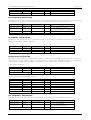
3.5.3.9 SMS outgoing
The short message protocol is shown below. Each packet has a header, which consists of the packet ID and the
packet length (exclusive header).
AT
ATCommand
Command
AT Frame
AT+CMD
TDPU
TPDU
Header
TPDU User data (max. 140 Bytes)
MsgID
64
Length
32
GPS data
@event
MsgID
1
<EOF>
Length
32
GPS data MsgID N
@send
0
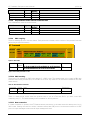
Figure 9: SMS frame
Packet ID
01
Packet
length
20
Data
Termination
41 12 98 33 AD F2 B4 FB 04 ED B3 03 00 E2 D0 24 01
BC 00 00 00 00 01 22 04 20 FF 45 04 02 06 09
00
Figure 10: GPS data packet ID 1 in SM
3.5.3.10 SMS Incoming
The protocol for requests via SMS is the same as if a SMS is sent. The requests have to be coded as 8Bit data
with the Data Coding Scheme (DCS) of the SMS set to 0xF4. Any other DCS as 0xF4 will be treated as 7bit text
(demo mode).
Table 15: SMS and Data Commands
Command
ID
01
Packet
length
OB
Data
Termination
01 01 00 00 00 00 00 00 00 01 00
00
Figure 11: Initiate a SMS with the GPS data packet sent to host 1
There is a demo mode, which sends the position back to you as a 7bit text SMS if you send a text SMS
containing only “P”. This demo message can be disabled for security reasons.
3.5.3.11 Data connection
If a data connection is opened, the AT-Firmware enters data mode. In the data mode the same protocol as in
SMS is used. Sending the ‘switch to online’ command will activate SiRF protocol on the data connection. All SiRF
protocol output messages are sent and all input messages will work.
GPS.G1-X-00001-P1
Page 17
AT Command Set Option User’s Manual
!
µ-blox ag
Warning: Do not send any commands, which could cause a reset of the GPS-module. Although
reconfiguration is possible over a data connection, it is not recommended to do so.
3.6 Special Function Pins
3.6.1 Power on/off Signal
The AT-Firmware generates a power signal for the GSM Modem at the SCK0 pin (see 3.4.2 for the configuration
of the signal). The power on/off signal is not generated if no power up mode is activated.
!
Note: The GPS-PS1E-AT does not support the Reset Signal. So the module has to be used in no power up
mode always.
3.6.2 Reset Signal
On the SCK1 pin a reset signal is generated. The reset signal is active low. If the AT_Firmware can’t
communicate with the modem, the reset line is activated for a second and the modem is reinitialized. The reset
signal is not generated if no power up is activated
!
Note: The GPS-PS1E-AT does not support the Reset Signal.
3.6.3 General Purpose Input/Outputs
Two GPIO from GPIO 0 – 11 can be configured as trigger inputs. GPIO 0-7 can be configured as outputs, which
can be set and cleared using SMS or a data connection. GPIO 8-11 can function as inputs only. All GPIO can be
read using SMS or a data connection.
GPS.G1-X-00001-P1
Page 18
AT Command Set Option User’s Manual
µ-blox ag
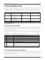
4 SUPPORTED GSM MODEMS
The AT-Firmware supports a sub-set of the AT command set which is necessary to control GSM modems.
However, the commands and the sequence of the commands required for the operation of GSM modems vary
from supplier to supplier. The AT-Firmware has been tested on the modem listed in Table 16. Note that not all
modems have a on/off or reset line on their interfaces and are therefore tested without reset line or in no power
up mode.
Modem
Siemens M20T
(M20)
Falcom A2D
Wavecom
WMOD2B
Tested Services
SMS: MO, MT
Voice Call: MO, MT
Data Call: MO, MT
SMS: MO, MT
Voice Call: MO, MT
Data Call: MO, MT
SMS: MO, MT
Voice Call: MO, MT
Data Call: MO, MT
HW Connections
1. Rx,Tx, On/off
2. Rx,Tx (No power up
mode)
1. Rx,Tx, On/off
Remark
Rx,Tx (No power up
mode)
Motorola d15
Nokia 6090
Not tested yet
Not tested yet
Table 16: Supported GSM Modems
4.1 How to set up your modem
Before a modem can be used with the AT option, the modem has to be configured. A PC with a serial port and
a terminal program is needed to do this. First the modem has to be connected to a serial port of the PC and the
terminal program has to be opened on that serial port. Normally after applying power, a switch on signal has to
be generated, to turn on the modem.
Sending AT<CR> should cause the modem to answer with OK<CR><LF>. If strange characters are returned the
baudrate of the serial port is wrong. If nothing is returned, the serial connection may be broken or the modem is
not on.
Once the modem is running, the following commands have to be sent:
Step
1
2
3
4
5
6
7
8
9
Command
AT&D0
AT&C0
AT+IPR=19200
AT+IFC=0,0
AT+CMGF=0
ATV0
ATE0
AT+CMEE=1
AT+CBST=0,0,1
10
AT&W
Description
The modem will now ignore the DTR signal
Ignore CTS
Sets the baudrate to 19200
Disables flow control in data mode
Set PDU mode (SMS)
Numerical return values
Echo off
Report mobile equipment errors
Set autobauding, if your modem doesn’t support autobauding (like the
Siemens M20), you have to set your connection type. If your call destination is
an analogue modem set 7,0,1 (V.32), if your destination is an ISDN modem
set 71,0,1 (V.110)
Save settings
Table 17: Configuration of the modem
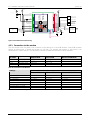
4.2 Recommended schematics and settings
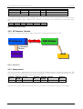
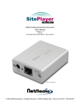
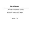
Figure 12 shows the lines that must be connected to the modem. Normally will connect all four lines to the
modem. If you want to use a mobile phone with AT interface, you probably don’t have access to the on/off and
reset signal. If you do not connect the on/off and reset lines (which is not recommended), you have to activate
no power up mode in the configuration.
If your modem has 3.3 levels logic levels on the on/off, reset, rx or tx lines, you don’t need a level shifter.
GPS.G1-X-00001-P1
Page 19
AT Command Set Option User’s Manual
µ-blox ag
Vcc
Vcc
Firmware Up-date
Normal Operation
GND
GND
NMI
TEST_I
WAKEUP_N
RX_3
RX_2
Voltage Regulator
Vant
PWRcontrol
Vcc
Vant
GND
Vant
1
2
3
4
5
6
7
8
9
10
11
12
13
14
15
16
17
18
19
20
21
GPSMS1E
Vcc
42
41
40
39
38
37
36
35
34
33
32
31
30
29
28
27
26
25
24
23
22
Vcc
GND
Level Modem on/off
Shifter
Level Modem reset
Shifter
Level Modem TX
Shifter Modem RX
RX0
TX0
RX1
TX1
SCK0
SCK1
Vbat
Vbat
Vcc
GND
RS 232
Level Shifter
GND GND
GND
Antenna Input
Figure 12: Recommended external wiring
4.2.1 Connection to the modem
The GPS receiver does only have to be connected to the serial port of the GSM Modem. Some GSM modems
support an external pin to switch the modem on (off resp.). For modem with support of this function, we
recommend to connect this pin. This allows the controller to restart the modem in case of problems.
MS1E/PS1E
pin name
TX0
RX0
SCK0
SCK1
Signal name
Modem Rx
Modem Tx
Modem on/off
Modem reset
Modem line
Siemens M20
USCRX
USCTX
IGNITION
-
Modem line
Falcom A2D
DATA_RX2
DATA_TX
SOFT_ON
RSTF
Modem line
Wavecom WMOD2D
RX
TX
-
Recommended values for
Siemens M20
Falcom A2D
Wavecom WMOD2D
2s
0s
AT^SMSO
1s
0s
AT+CNMI=2,2,0,0,0
3s
0s
AT+CPOF
10s
0s
Yes
AT+CNMI=2,2,0,0,0
Table 18: Connections to the Modems
Settings
On pulse length
Off pulse length
Off command
Wait after on pulse
Wait after off pulse
No Power up Mode
Pre registration init script
Post registration init script
3s
0s
AT+CPOF
10s
0s
AT+CNMI=2,2,0,0,0
Table 19: Recommended settings
GPS.G1-X-00001-P1
Page 20
AT Command Set Option User’s Manual
µ-blox ag
5 µ-TRACKER – DEMO PROGRAM FOR THE AT FIRMWARE
µ-blox offers the µTracker demo software running on Win9x or WinNT which allows the user to configure the AT
command option easily.
5.1 Views
µTracker has 3 different views, the SiRF-console view, the AT-console view and the map view.
5.1.1 SiRF console
The SiRF console shows messages from your µ-blox GPS receiver, which is connected to a serial port. The upper
part shows which messages have been received, the lower part shows decoded debug messages.
Figure 13: SiRF console view
While the SiRF console is active you can access the AT-Firmware settings dialog with the menu entry GPS-xS1 ->
Settings or you press the knob symbol on the toolbar.
Pressing the right arrow symbol on the toolbar will send an external event message to the GPS-xS1E-AT. Pressing
the button with the question mark will poll the GPS-xS1E-AT status.
5.1.2 AT console
The AT console has two modes, normal and direct mode. In normal you can use this console to monitor and to
send AT-commands to the modem connected to the GPS-xS1E-AT. In direct mode the AT console controls a
modem, which is connected directly to the pc.
In normal mode the upper part of the window displays the AT commands which are sent from the GSM-modem
to the GPS-xS1E-AT. You can enter an AT-command in the edit box. Pressing enter will send the command to
the GPS-xS1E-AT, which will send it to the GSM-modem. The ending character of the AT command can be
selected in the drop-down-list. If you select another ending character than <CR>, the selection will be set to
<CR> again after the command is sent. In direct mode, no information is added in the lower part of the
window.
In direct mode the toolbar and the corresponding menu entry get active. You can use the console the same way
as in normal mode.
Pressing the left arrow symbol will open a dialog for sending a SMS request to the GPS-MS1E-AT. Incoming SMS
will be decoded and displayed in the lower part of the window.
GPS.G1-X-00001-P1
Page 21
AT Command Set Option User’s Manual
µ-blox ag
Figure 14: Console view
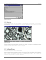
5.1.3 Map view
The map displays a bitmap, which can be calibrated to longitude/latitude. If a data packet 1 or 64 is decoded in
an incoming SMS, the position will be marked with cross on the map. With the add point button a point can be
added manually.
Figure 15: Map view
Pressing the right mouse button in the map view will show up a menu, which lets you set the reference points of
the map. Instead of setting the reference points each time the map is loaded, a map calibration file can be
written in a text editor. See the sample *.mcf file for the syntax.
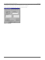
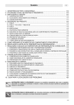
5.2 Settings Dialog
The settings dialog lets you configure the AT firmware.
When the dialog is opened the configuration has to be uploaded first. This is done with the ‘Get Configuration’
button. To download the configuration to the GPS receiver press the ‘Set Configuration’ button. If ‘Write to
Flash’ is checked, the configuration will be stored in the flash memory. If ‘Write to flash’ is checked, the
downloaded configuration will be written into flash memory.
GPS.G1-X-00001-P1
Page 22
AT Command Set Option User’s Manual
µ-blox ag
A configuration can be saved to a file and reloaded later. The ‘OK’ and ‘Cancel’ buttons do not have any other
function than closing the dialog. They do not influence down- or uploading.
There is a standard configuration file (*.uac) for each supported modem.
Figure 16: Configuration
GPS.G1-X-00001-P1
Page 23
AT Command Set Option User’s Manual
µ-blox ag
6 CONFIGURATION EXAMPLES
The AT Firmware has to be set up for the communication in the GSM network prior to any user specific
configuration (refer to Recommended schematics and settings).
Set the PIN code and the Service Center Address (SCA). The SIM card dealer provides the SCA. Clear the SCA
field if the AT firmware should use the pre-programmed SCA on the SIM card.
Enter the destination address (the phone number the SM shall be sent to) in the host 0 field. For voice and data
connection we will use host 2.
6.1 Tracking an object with a position update via SMS every 1 minute
This is a typical application for the timer event.
Go to the trigger tab and set the interval of timer0 to 60 seconds. The timer event will now occur every 60
seconds.
Afterwards, the action of the timer0 event has to be configured. This is done in the action tab.
Select the timer0 event. Choose send SM as action and host 0 as destination; enter 1 as the first packet ID.
Packet 1 contains time and position and is assembled at send time.
Go back to the general tab and press the set configuration button.
6.2 Tracking an object with a position update via SMS every 500m
This is a typical application for the movement event.
Set the distance of the movement trigger in the trigger tab to 500m.
Select the movement event in the action tab. Choose Send SM as action and host 0 as destination. Enter 64 as
the first packet ID.
Go back to the general tab and press the set configuration button.
6.3 Send a position and an identification string if a button is pressed
Connect the button to a GPIO and specify this GPIO in the trigger tab.
Select GPIO trigger 0, send SM and host 0 in the action tab. Packet 64 stores the position at the time, the button
is pressed. Take packet 64 as the second packet for the identification string. The content of packet ID 128 can
be set in the data tab. Select the ID 128 and enter the user data in ASCII or hexadecimal.
Go back to the general tab and press the set configuration button.
6.4 Voice connection and position via SMS if a button is pressed
Connect the button to two GPIO and specify these GPIO in the trigger tab.
Select GPIO trigger 0, send SM and host 0 in the action tab. Packet 64 stores the position at the time the button
is pressed.
Select GPIO trigger 1, voice call and host 1 in the action tab.
Go back to the general tab and press the set configuration button.
If you press the button now, an SM will be sent and after that the voice connection will be opened. While the
voice connection is up, SM send and poll will work.
6.5 Online tracking if a certain area is entered
First, define your area in form of upper and lower latitude and longitude.
GPS.G1-X-00001-P1
Page 24
AT Command Set Option User’s Manual
µ-blox ag
Go to the trigger tab and enter your area in the area trigger settings, set the repetition rate to 180s. Remember
to put the greater coordinates in the first fields. Select Data call to host 1 as action for the area trigger.
Go back to the general tab and press the set configuration button.
As soon as you enter the defined area, a data connection will be opened to host 2. You have to answer the call
to your host. Once the connection is up you can poll position information, or you can send a command to switch
to SiRF protocol. Sirf protocol output will be sent over the data connection.
GPS.G1-X-00001-P1
Page 25
AT Command Set Option User’s Manual
µ-blox ag
7 LIMITATIONS
1. Serial ports 2 and 3 Mode are not supported in Trickle Power and Push to Fix Mode.
2. If the AT-Firmware is used on a GPS-PS1E, the GPIO triggers cannot be used. Additionally, certain GSM
Modem Control Signals (Reset, Powerup) are not available.
3. Depending on the GSM modem and network, not all features of the AT-Firmware may be available.
4. The current consumption in low power modes can be estimated with the normal formula from the low
power application note, but 18mA have to be added to that value.
GPS.G1-X-00001-P1
Page 26
AT Command Set Option User’s Manual
µ-blox ag
A USED AT COMMANDS
This list summarizes all AT commands sent by the AT-Firmware and the expected reactions.
AT command
AT
AT&D0
ATV0
AT+CPIN=xxxx
AT+CPIN?
ATDxxxxxxxx
AT+CREG?
ATA
AT+CMGS=xx
AT+CNMI=2,2,0,0,0
AT+CMEE=1
ATH
AT+CHUP
Expected reactions
OK (0), ERROR (4)
OK (0), ERROR (4)
OK (0)
OK, ERROR
+CPIN: SIM PIN, +CPIN: SIM READY
OK, ERROR, NO CARRIER if connection is terminated
+CREG: x,y
OK, ERROR
Before PDU is sent: 0D 0A 3E 20, after PDU: +CMGS xxx
OK, CME ERROR 515
OK
OK
OK
Table 20: Used AT commands
GPS.G1-X-00001-P1
Page 27
AT Command Set Option User’s Manual
µ-blox ag
B TYPE DEFINITIONS
Field name
Pin
Flags
Type
STRING
ULONG
Length
11
4
GPIO_out
GPIO_Init
Reserved
SCA Number
Host 1 Number
Host 2 Number
Host 3 Number
Host 4 Number
Modem Settings
Trigger Settings
Reserved
Timer 0
Timer 1
Area
Move
Speed
Log full
GPIO 0
GPIO 1
External
Reserved
BYTE
BYTE
BYTE
STRUCT
STRUCT
STRUCT
STRUCT
STRUCT
STRUCT
STRUCT
BYTE
STRUCT
STRUCT
STRUCT
STRUCT
STRUCT
STRUCT
STRUCT
STRUCT
STRUCT
BYTE
1
1
8
22
22
22
22
22
Unit
Remark
Zero terminated string
Enable AT: 0x01
AT debug messages: 0x02
Demo message: 0x04
No power up mode: 0x08
GPIO output mask
GPIO output initial setting mask
Reserved for future use
See Table 24
See Table 24
See Table 24
See Table 24
See Table 24
See Table 22
See Table 23
Set to zero
See Table 25
See Table 25
See Table 25
See Table 25
See Table 25
See Table 25
See Table 25
See Table 25
See Table 25
Set to zero
Unit
s
s
s
s
Remark
39
11
11
11
11
11
11
11
11
11
11
11
Table 21: Configuration Structure
Field name
On pulse Length
Off pulse Length
Wait after on pulse
Wait after off pulse
Off command
Search timeout
Off time
On timeout
Reserved
Pre registration init
Post registration init
Type
UBYTE
UBYTE
UBYTE
UBYTE
STRING
UBYTE
UBYTE
UBYTE
BYTE
STRING
STRING
Length
1
1
1
1
10
1
1
1
2
100
100
Zero terminated string
min
min
min
Zero terminated string, command separator: CR
Zero terminated string, command separator: CR
Table 22 Modem Settings Structure
GPS.G1-X-00001-P1
Page 28
AT Command Set Option User’s Manual
Field name
Timer 0 period
Timer 1 period
Speed period
Area period
Lat 1
Lon 1
Lat 2
Lon 2
Speed
Radius
Reserved
Trigger Flags
GPIO Trigger 0
GPIO Trigger 1
Total Length
Type
ULONG
ULONG
ULONG
ULONG
Float
Float
Float
Float
Short
Short
BYTE
BYTE
UBYTE
UBYTE
µ-blox ag
Length
4
4
4
4
4
4
4
4
2
2
4
1
1
1
43
Unit
s
s
s
s
Deg
Deg
Deg
Deg
m/s
m*10
Remark
Length
1
1
20
22
Unit
Remark
Length of the Host 4 Address
Type of Host 4 Address, always 0x91
International number, without preceding +
Length
1
8
1
1
11
Unit
Remark
0x01 : AREA_INSIDE
GPIO Number 0-11
GPIO Number 0-11
Table 23 Trigger Settings Structure
Field name
Address length
Address type
Address
Total Length
Type
UBYTE
UBYTE
STRING
Table 24: Phone number structure
Field name
Action
Data Packets
Host
Flags
Total Length
Type
UBYTE
UBYTE
UYBTE
UYBTE
1-4
Always 0
Table 25: Event configuration structure
These type definitions are usefuel in writing software, which communicates with the AT firmware. These
definitions are also available as a the file at_type.h. The byte order is big endian. All structures are filled up with
padding bytes, so that the size is a multiple of four.
#define
#define
#define
#define
#define
MAX_DP
MAX_DP_BYTES
DEF_DP_BYTES
NUM_OF_DEF_DP
MAX_HOST
8
138
512
32
4
/*
/*
/*
/*
/*
maximum number of data packets per sm */
comes from maximum length of an SMS (140-2) */
maximum size of all user packets together */
number of default user data packets */
highest host number */
/* configuration flags */
#define AT_OPTION
#define AT_DEBUG_MSG
#define REPLY_TO_SENDER
#define NO_POWERUP
0x01
0x02
0x04
0x08
/* Trigger Flags */
#define AREA_INSIDE
#define P2F_TRIGGER
0x01
0x02
#define LATLONSCALE
1000000
/* number of phone numbers */
#define PHONE_NUMBERS 4
/* init script structure */
#define INIT_SCRIPT_LENGHT 100
/* data
#define
#define
#define
#define
#define
#define
#define
poll messages */
REQ_DATA
REQ_DATA_P2F
REQ_SET_TRIGGER
REQ_SET_EVENT
REQ_SET_LP_MODE
REQ_SET_GPIO
REQ_RESERVED1
GPS.G1-X-00001-P1
1
2
32
33
34
35
0x2B /* + is reserved, because this is used to detect connection loss */
Page 29
AT Command Set Option User’s Manual
#define
/* data
#define
#define
#define
µ-blox ag
REQ_RESERVED2
0x38 /* 8 is reserved, because this is used to detect connection loss */
mode only requests */
REQ_ONLINE
128
REQ_HANGUP
129
REQ_TIMER_RESET
130
/* Events */
typedef enum GSMEvents
{
NO_EVENT = 0,
TIMER0,
TIMER1,
AREA,
MOVE,
SPEED,
LOGFULL,
GPIO0,
GPIO1,
EXTERNEV,
INTERNEV,
EVENTS
};
/* Data Packet structs*/
typedef struct
{
DOUBLE TOW;
int Lat;
int Lon;
short Alt;
short Sog;
short
Cr;
short Cog;
uint16 Week;
uint16 GPIO;
UBYTE Mode;
UBYTE DOP;
UBYTE
SVs;
UBYTE Event;
}DP_ID1_Struct;
/* Status message */
typedef struct
{
UBYTE ModemState;
UBYTE Event;
UBYTE Action;
UBYTE NrEvOnSMSStack;
UBYTE NrEvOnCallStack;
UBYTE res1;
UBYTE res2;
UBYTE res3;
UBYTE res4;
UBYTE res5;
UBYTE res6;
UBYTE sw_ver0;
UBYTE sw_ver1;
}AT_Status_Struct;
/* user data packet struct */
typedef struct
{
UBYTE Length[NUM_OF_DEF_DP];
UBYTE Data[DEF_DP_BYTES];
}DP_USER_Struct;
/* phone numbers */
typedef struct
{
UBYTE Length;
UBYTE Type;
UBYTE Number[20];
}GSM_Phone_Number_Struct;
/* event config */
typedef struct
{
UBYTE Action;
UBYTE DPIDs[MAX_DP];
UBYTE Host;
UBYTE Flags;
}AT_Event_struct;
/* trigger config */
typedef struct
{
GPS.G1-X-00001-P1
Page 30
AT Command Set Option User’s Manual
µ-blox ag
uint32 TimerPeriod0;
uint32 TimerPeriod1;
uint32 SpeedPeriod;
uint32 AreaPeriod;
float Lat1;
float Lon1;
float Lat2;
float Lon2;
short Speed; /* scale 1 */
short Radius; /* scale *10m */
UBYTE Res[4];
UBYTE
Flags;
UBYTE GPIOTrigger0;
UBYTE GPIOTrigger1;
}AT_Triggers_struct;
/* modem config */
typedef struct
{
UBYTE OnPulsLen; /* if zero the pin is high, while the modem should be on */
UBYTE OffPulsLen; /* if zero, soft off is used */
UBYTE OnWait;
/* time after on pulse before first command is sent */
UBYTE OffWait;
/* time to wair after off pulse */
UBYTE OffCmd[10]; /* soft off at command */
UBYTE CRegTimeout;/* timeout in s/10 after failed gsm registration*/
UBYTE CRegOffTime;/* in min. wait this time after CRegTimeout */
UBYTE OnTime;
/* stays on this time after an action */
UBYTE Reserved0; /* reserved for future use */
UBYTE Reserved1;
/* reserved for future use */
UBYTE PreRegInit[INIT_SCRIPT_LENGHT];
UBYTE PostRegInit[INIT_SCRIPT_LENGHT];
}AT_Modem_struct;
/* misc config */
typedef struct
{
UBYTE PIN[11];
ULONG Flags;
UBYTE GPIO_out; /* only GPIOs 0-7 are supported for online setting */
UBYTE GPIO_init;
UBYTE Res[8];
GSM_Phone_Number_Struct
SCA;
GSM_Phone_Number_Struct Host[PHONE_NUMBERS];
}AT_General_struct;
/* all config */
typedef struct
{
AT_General_struct
AT_Modem_struct
AT_Triggers_struct
AT_Event_struct
}AT_Config_struct;
GPS.G1-X-00001-P1
General;
Modem;
Trig;
Events[EVENTS];
Page 31
AT Command Set Option User’s Manual
µ-blox ag
C RELATED DOCUMENTS
§
GPS.G1-X-00005 - GPS-MS1E/GPS-PS1E Protocol Specification
§
GPS.G1-MS1-00002 - GPSMS1E Datasheet
All these documents are available on our homepage (http://www.u-blox.com).
GPS.G1-X-00001-P1
Page 32
AT Command Set Option User’s Manual
µ-blox ag
D GLOSSARY
DOP
GPIO
GPS
GSM
MO
MT
PIN
SCA
SIM
SM
SMS
SV
TOW
Dilusion of Precision
General Purpose Input / Output
Global Positioning System
Global System of Mobile Communication
Mobile Originated
Mobile Terminated
Personal Identification Number
Service Center Address
Subscriber Identity Module
Short Message
Short Message Service
Space Vehicle (Satellite)
Time of Week (GPS Time)
GPS.G1-X-00001-P1
Page 33
AT Command Set Option User’s Manual
µ-blox ag
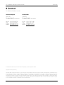
E CONTACT
For further information contact:
Technical Support
Headquarter
µ-blox ag
Zürcherstrasse 68
CH-8800 Thalwil, Switzerland
µ-blox ag
Zürcherstrasse 68
CH-8800 Thalwil, Switzerland
Phone: +41-1-722 74 74
FAX:
+41-1-722 74 47
E-mail: [email protected]
WWW: http://www.u-blox.com
Phone: +41-1-722 74 44
FAX:
+41-1-722 74 47
E-mail: [email protected]
WWW: http://www.u-blox.com
All trademarks mentioned in this document are property of their respective owners.
Copyright © 2000, µ-blox ag
This data sheet contains information on µ-blox products in the sampling and initial production phases of development. The specifications in
this data sheet are subject to change at µ-BLOX' discretion. µ-blox assumes no responsibility for any claims or damages arising out of the use
of this document, or from the use of modules based on this document, including but not limited to claims or damages based on
infringement of patents, copyrights or other intellectual property rights. µ-blox makes no warranties, either expressed or implied with respect
to the information and specifications contained in this document. Performance characteristics listed in this document are estimates only and
do not constitute a warranty or guarantee of product performance.
GPS.G1-X-00001-P1
Page 34
AT Command Set Option User’s Manual
µ-blox ag
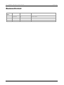
REVISION HISTORY
Revision
Index
Date
Name
Status / Comments
19/10/00
PE
Initial version
27/10/00
CB
Release Version
GPS.G1-X-00001-P1
Page 35