1
GOT-A900 Series
User's Manual (Connection System Manual)
Mitsubishi Graphic Operation Terminal
• SAFETY INSTRUCTIONS •
(Always read these instructions before using this equipment.)
Before using this product, please read this manual and the relevant manuals introduced in this manual carefully
and pay full attention to safety to handle the product correctly.
The instructions given in this manual are concerned with this product. For the safety instructions of the
programmable controller system, please read the CPU module user's manual.
In this manual, the safety instructions are ranked as "DANGER" and "CAUTION".
DANGER
Indicates that incorrect handling may cause hazardous conditions,
resulting in death or severe injury.
! CAUTION
Indicates that incorrect handling may cause hazardous conditions,
resulting in medium or slight personal injury or physical damage.
!
Note that the ! CAUTION level may lead to a serious consequence according to the circumstances.
Always follow the instructions of both levels because they are important to personal safety.
Please save this manual to make it accessible when required and always forward it to the end user.
[Design Instructions]
! DANGER
• Some failures of the GOT main unit, communication module, communication board or cable may
keep the outputs on or off.
An external monitoring circuit should be provided to check for output signals which may lead to a
serious accident.
Not doing so can cause an accident due to false output or malfunction.
• If a communication fault (including cable disconnection) occurs during monitoring on the GOT,
communication between the GOT and PLC CPU is suspended and the GOT becomes inoperative.
For bus connection
: The CPU becomes faulty and the GOT inoperative.
For other than bus connection
: The GOT becomes inoperative.
A system where the GOT is used should be configured to perform any significant operation to the
system by using the switches of a device other than the GOT on the assumption that a GOT
communication fault will occur.
Not doing so can cause an accident due to false output or malfunction.
! CAUTION
• Do not bundle the control and communication cables with main-circuit, power or other wiring.
Run the above cables separately from such wiring and keep them a minimum of 100mm apart.
Not doing so noise can cause a malfunction.
[Mounting Instructions]
! DANGER
• Before installing or removing the GOT main unit to or from an enclosure, always switch off the GOT
power externally in all phases.
Not doing so can cause a module failure or malfunction.
• Before loading or unloading the communication board, communication module or memory board to or
from the GOT, always switch off the GOT power externally in all phases.
Not doing so can cause a module failure or malfunction.
! CAUTION
• The GOT should be used in the environment given in the general specifications of the GOT user's
manual.
Not doing so can cause an electric shock, fire, malfunction or product damage or deterioration.
• When mounting the GOT main unit to an enclosure, tighten the mounting screws in the specified
torque range.
Undertightening can cause a drop, short circuit or malfunction.
Overtightening can cause a drop, short circuit or malfunction due to the damage of the screws or
module.
• When loading the communication board or communication module to the GOT main unit, fit it to the
connection interface of the GOT and tighten the mounting screws in the specified torque range.
Undertightening can cause a drop, failure or malfunction.
Overtightening can cause a drop, failure or malfunction due to the damage of the screws or
module.
• When loading the memory board into the GOT main unit, load it into its corresponding GOT slot
and tighten the mounting screws in the specified torque range.
Undertightening can cause a malfunction due to a contact fault.
Overtightening can cause a malfunction due to the damage of the screws or module.
• When loading the PC card into the GOT main unit, insert and push it into its corresponding GOT
slot until the PC card eject button comes up.
Not doing so can cause a malfunction due to a contact fault.
• Before loading or unloading the PC card to or from the GOT, set the memory card access switch to
the OFF position.
Not doing so can cause the PC card data to be corrupted.
[Wiring Instructions]
! DANGER
• Before starting wiring, always switch off the GOT power externally in all phases.
Not doing so may cause an electric shock, product damage or malfunction.
! CAUTION
• Always earth the FG, LG and earth terminals of the GOT power supply section to the protective
earth conductor.
Not doing so may cause an electric shock or malfunction.
• Correctly wire the power supply module on the GOT after confirming the rated voltage and terminal
arrangement of the product.
Not doing so can cause a fire or failure.
• Tighten the terminal screws of the GOT power supply section in the specified torque range.
Undertightening can cause a short circuit or malfunction.
Overtightening can cause a short circuit or malfunction due to the damage of the screws or
module.
• Exercise care to avoid foreign matter such as chips and wire offcuts entering the module.
Not doing so can cause a fire, failure or malfunction.
• Plug the bus connection cable by inserting it into the connector of the connected module until it
"clicks".
After plugging, check that it has been inserted snugly.
Not doing so can cause a malfunction due to a contact fault.
• Plug the communication cable into the connector of the connected module and tighten the mounting
and terminal screws in the specified torque range.
Undertightening can cause a short circuit or malfunction.
Overtightening can cause a short circuit or malfunction due to the damage of the screws or module.
[Test Operation Instructions]
! DANGER
• Before performing test operation (bit device on/off, word device's present value changing,
timer/counter's set value and present value changing, buffer memory's present value changing) for a
user-created monitor screen, system monitoring, special module monitoring or ladder monitoring,
read the manual carefully to fully understand how to operate the equipment.
During test operation, never change the data of the devices which are used to perform significant
operation for the system.
False output or malfunction can cause an accident.
[Startup/Maintenance Instructions]
! DANGER
• When power is on, do not touch the terminals.
Doing so can cause an electric shock or malfunction.
• Before starting cleaning or terminal screw retightening, always switch off the power externally in all
phases.
Not switching the power off in all phases can cause a module failure or malfunction.
Undertightening can cause a short circuit or malfunction.
Overtightening can cause a short circuit or malfunction due to the damage of the screws or module.
! CAUTION
• Do not disassemble or modify the module.
Doing so can cause a failure, malfunction, injury or fire.
• Do not touch the conductive and electronic parts of the module directly.
Doing so can cause a module malfunction or failure.
• The cables connected to the module must be run in ducts or clamped.
Not doing so can cause the module or cable to be damaged due to the dangling, motion or
accidental pulling of the cables or can cause a malfunction due to a cable connection fault.
• When unplugging the cable connected to the module, do not hold and pull the cable portion.
Doing so can cause the module or cable to be damaged or can cause a malfunction due to a cable
connection fault.
[Disposal Instructions]
! CAUTION
• When disposing of the product, handle it as industrial waste.
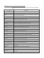
Revisions
*The manual number is given on the bottom left of the back cover.
Print Date
Nov,1998
Jan,1999
*Manual Number
SH(NA)-4015-A
SH(NA)-4015-B
Mar,1999
SH(NA)-4015-C
Revision
First edition
Partial correctionx
Section 3.1, Section 3.2, Section 3.3
Partial additionx
Section 1.1, Section 4.1, Section 4.2, Section 5.1, Section 6.1,
Section 7.1, Section 8.1, Section 10.1, Section 11.1, Section 12.1,
Section 13.1, Section 14.1, Section 15.1, Section 15.2
Additionx
Section 15.3, Index
Partial correctionx
Section 2.1, Section 2.4
This manual confers no industrial property rights or any rights of any other kind, nor does it confer any patent
licenses. Mitsubishi Electric Corporation cannot be held responsible for any problems involving industrial property
rights which may occur as a result of using the contents noted in this manual.
1999 MITSUBISHI ELECTRIC CORPORATION
INTRODUCTION
Thank you for choosing the Mitsubishi Graphic Operation Terminal.
Before using the equipment, please read this manual carefully to use the equipment to
its optimum.
Please forward a copy of this manual to the end user.
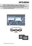
Whereabouts and Usage of This Manual
The manuals relating to the GOT 900 series are available in the following types.
The manuals are classified according to their purposes. Please read the proper
manuals to understand the handling, operation and functions of the GOT unit and
SW1D5C-GOTRE-PACK.
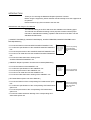
[ A975GOT-TBA/TBD(-B), A970GOT-TBA/TBD(-B), A970GOT-SBA/SBD, A960GOT-EBA/EBD User’s
Manual(Hardware) ]
• To know the features of the A975GOT/A970GOT/A960GOT unit.
• To confirm the specifications of the A975GOT/A970GOT/A960GOT
unit.
• To know the part names of the A975GOT/A970GOT/A960GOT unit.
• To know how to install and wire the A975GOT/A970GOT/A960GOT
unit.
• To know the outline dimension drawing of the
A975GOT/A970GOT/A960GOT unit.
A975GOT-TBA/TBD(-B)
A970GOT-TBA/TBD(-B)
A970GOT-SBA/SBD
A960GOT-EBA/EBD
user's Manual
(Hardware)
Found in the packing
of the A975GOT/
A970GOT/A960GOT
unit.
[ A985GOT Graphic Operation Terminal User’s Manual(Hardware) ]
• To know the features of the A985GOT unit.
• To confirm the specifications of the A985GOT unit.
• To know the part names of the A985GOT unit.
• To know how to install and wire the A985GOT unit.
• To know the outline dimension drawing of the A985GOT unit.
A985GOT
Graphic Operation
Terminal
User's Manual
(Hardware)
Found in the packing
of the A985GOT unit.
[ GOT-A900 Series Option Unit User's Manuals ]
• To know the features of the corresponding GOT-A900 series option
unit.
• To confirm the specifications of the corresponding GOT-A900 series
option unit.
• To know the part names of the corresponding GOT-A900 series
option unit.
• To know the outline dimension drawing of the corresponding GOTA900 series option unit.
GOT-A900 Series
Option Unit
User's Manuals
Found in the packing
of the corresponding
GOT-A900 series
option unit.
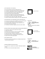
[ GOT-A900 Series User’s Manual ]
• To know the features of the GOT-A900 series unit.
• To confirm the component devices of the GOT-A900 series.
• To confirm the specifications of the GOT-A900 series unit.
• To know the part names of the GOT-A900 series unit.
• To fit various units to the GOT-A900 series.
• To know how to install and wire the GOT-A900 series unit.
• To know how to maintain and inspect the GOT-A900 series.
• To confirm the error codes of the GOT-A900 series.
• To know the outline dimension drawing of the GOT-A900 series unit.
GOT-A900 Series
User's Manual
Available as an option.
[ GOT-A900 Series User’s Manual(Connection System Manual) ]
• To know the connection forms available for the GOT-A900 series.
• To confirm the specifications of each connection form.
• To know the system configuration of each connection form.
• To know how to set the unit used.
• To confirm the connection diagrams of the connection cables.
SW1D5C-GOTRE-MANU
Online manual⋅Tutorial
Contained in the
SW1D5C-GOTRE-MANU
Online manual⋅Tutorial as
PDF data.
* The paper manual is also available
as an option.
[ SW1D5C-GOTRE-PACK Operating Manual ( Drawing Software Manual ) ]
• To install the software into the personal computer.
• To start each software.
• To know how to connect the personal computer and GOT.
• To know the screen makeup of the software.
• To grasp the outline of various monitoring functions.
• To know the procedure of displaying the monitor screen.
• To know how to use the help function.
SW1D5C-GOTRE-PACK
Operating Manual
(Drawing Software Manual)
Found in the packing
of SW1D5C-GOTRE-PACK.
[ GOT Operations Guide ]
• To learn the sequence of operations by creating a simple screen
using the drawing software.
SW1D5C-GOTRE-MANU
Online manual⋅Tutorial
Contained in the
SW1D5C-GOTRE-MANU
Online manual⋅Tutorial.
[ SW1D5C-GOTRE-PACK Help Functions]
• To confirm how to operate each software of SW1D5C-GOTREPACK.
• To confirm how to set various object functions.
SW1D5C-GOTRE-PACK
Incorporated in
each software of
SW1D5C-GOTRE-PACK
[ GOT-A900 Series Operating Manual ( Extended • Option Functions Manual ) ]
• To perform the utility function.
• To perform the system monitoring function.
• To perform the ladder monitoring function.
• To perform the special function unit monitoring function.
• To perform the network monitoring function.
SW1D5C-GOTRE-MANU
Online manual⋅Tutorial
Contained in the
SW1D5C-GOTRE-MANU
Online manual⋅Tutorial as
PDF data.
* The paper manual is also available
as an option.
Abbreviations, generic terms and special terms used in this manual
Abbreviations, generic terms and special terms used in this manual are described as
follows:
Abbreviations, generic terms
and special terms
Description
A985GOT
Generic term of A985GOT-TBA and A985GOT-TBD
A975GOT
Generic term of A975GOT-TBA, A975GOT-TBD, A975GOT-TBA-B and A975GOT-TBD-
A970GOT
Generic term of A970GOT-TBA, A970GOT-TBD, A970GOT-SBA, A970GOT-SBD,
A970GOT-TBA-B and A970GOT-TBD-B
A960GOT
Generic term of A960GOT-EBA and A960GOT-EBD
GOT
Generic term of A985GOT, A975GOT, A970GOT and A960GOT
Memory
Abbreviation of memory (flash memory) in the GOT
OS
Abbreviation of GOT system software
A9GT-BUSS
Abbreviation of A9GT-BUSS type bus connection board
A9GT-BUS2S
Abbreviation of A9GT-BUS2S type multi-drop bus connection board
Bus connection board
Generic term of A9GT-BUSS and A9GT-BUS2S
A9GT-RS4
Abbreviation of A9GT-RS4 type serial communication board
A9GT-RS2
Abbreviation of A9GT-RS2 type serial communication board
Serial communication board
Generic term of A9GT-RS4 and A9GT-RS2
Communication board
Generic term of bus connection board and serial communication board
A7GT-J71AP23
Abbreviation of A7GT-J71AP23 type data link unit
A7GT-J71AR23
Abbreviation of A7GT-J71AR23 type data link unit
A7GT-J71AT23B
Abbreviation of A7GT-J71AT23B type data link unit
Data link unit
Generic term of A7GT-J71AP23, A7GT-J71AR23 and A7GT-J71AT23B
A7GT-J71LP23
Abbreviation of A7GT-J71LP23 type network unit
A7GT-J71BR13
Abbreviation of A7GT-J71BR13 type network unit
Network unit
Generic term of A7GT-J71LP23 and A7GT-J71BR13
A8GT-J61BT13
Abbreviation of A8GT-J61B13 CC-Link communication unit
A8GT-J61BT15
Abbreviation of A8GT-J61B15 CC-Link communication unit
CC-Link communication unit
Generic term of A8GT-J61BT13 and A8GT-J61BT15
Communication unit
Generic term of data link unit, network unit and CC-Link communication unit
Protection sheet
Abbreviation of A9GT-70PSCL, A9GT-70PSC, A9GT-60PSCL and A9GT-60PSC type transparent
protection sheets
Backlight
Abbreviation of A9GT-70LTT and A9GT-70LTS type backlights
Debug stand
Abbreviation of A9GT-70STAND type debug stand
PC card ( memory card )
Abbreviation of PC card with PCMCIA Ver.2.1
Memory board
Abbreviation of A9GT-FNB, A9GT-FNB1M, A9GT-FNB2M, A9GT-FNB4M type option function
memory board
External I/O unit
Abbreviation of A9GT-70KBF type external I/O interface unit
Abbreviations, generic terms and
special terms
Description
QnACPU
Generic term of Q2ACPU, Q2ACPU-S1, Q3ACPU and Q4ACPU CPU units
AnUCPU
Generic term of A2UCPU, A2UCPU-S1, A3UCPU and A4UCPU CPU units
AnACPU
Generic term of A2ACPU, A2ACPU-S1 and A3ACPU CPU units
AnNCPU
Generic term of A1NCPU, A2NCPU, A2NCPU-S1 and A3NCPU CPU units
Q2ASCPU
Generic term of Q2ASCPU and Q2ASCPU-S1 CPU units
Q2ASHCPU
Generic term of Q2ASHCPU and Q2ASHCPU-S1 CPU units
A2US(H)CPU
Generic term of A2USCPU, A2USCPU-S1 and A2USHCPU-S1 CPU units
AnS(H)CPU
Generic term of A1SCPU, A1SHCPU, A2SCPU and A2SHCPU CPU units
A1SJ(H)CPU
Generic term of A1SJCPU-S3 and A1SJHCPU CPU units
FX0 series
Generic term of FX0 series CPU unit
FX0N series
Generic term of FX0N series CPU unit
FX0S series
Generic term of FX0S series CPU unit
FX1 series
Generic term of FX1 series CPU unit
FX2 series
Generic term of FX2 series CPU unit
FX2C series
Generic term of FX2C series CPU unit
FX2N series
Generic term of FX2N series CPU unit
FX2NC series
Generic term of FX2NC series CPU unit
Drawing software
Abbreviation of image creation software GOT Screen Designer for GOT900
Data conversion software
Abbreviation of data conversion software GOT Converter for GOT900
Debug software
Abbreviation of debugging software GOT Debugger
Object
Setting data for dynamic image
Windows95
Abbreviation of Microsoft Windows95∗
Windows NT4.0
Abbreviation of Microsoft Windows NT Workstation 4.0∗
Windows
Generic term of Windows95 and Windows NT4.0
Personal Computer
Windows compatible Personal Computer that can install SW1D5C-GOTRE-PACK
1
1
*1 Microsoft Windows95 and Microsoft Windows NT Workstation 4.0 are the trademarks of Microsoft Corporation, U.S.
Manual
The following manuals related to this product are available. Obtain the manuals as
required the according to this table.
• Related manual
Manual name
Manual number (Model code)
A985GOT Graphic Operation Terminal User’s Manual (Hardware)
Explains the specifications, part names, and grounding of the A985GOT.
(Found in the packing of the A985GOT unit)
IB-80019
(13JQ15)
A975GOT-TBA/TBD(-B), A970GOT-TBA/TBD(-B), A970GOT-SBA/SBD, A960GOT-EBA/EBD
User’s Manual(Hardware)
Explains the specifications, part names, and grounding of the A975GOT/A970GOT/A960GOT.
(Found in the packing of the A975GOT/A970GOT/A960GOT unit)
IB-80032
(13JN45)
GOT-A900 Series User’s Manual
Explains the specifications, general system configuration, component devices, part names, option
unit loading methods, installation and wiring methods, maintenance and inspection methods, and
error codes of the GOT-A900 series unit.
(Available as option)
SH-4005
(13JL70)
GOT-A900 Series User’s Manual (Connection System Manual)
Gives the specifications, system configuration, setting method and connection diagram of each
connection form available for the GOT-A900 series.
(Available as option)
SH-4015
(13JL79)
GOT-A900 Series Operating Manual (Extended • Option Functions Manual)
Provides the specifications of the utility, system monitoring, ladder monitoring, special function unit
monitoring and network monitoring functions available for the GOT-A900 series and how to
operate the dedicated monitor screen.
(Available as option)
SH-4014
(13J945)
SW1D5C-GOTRE-PACK Operating Manual
Deals with how to install and start the SW1D5C-GOTRE-PACK, its system configuration, the
screen makeup of the software package, the general description of various monitoring functions,
the procedure for displaying the monitor screen on the GOT, and how to use the help function.
(Found in the packing of the SW1D5C-GOTRE-PACK)
IB-66885
(13J943)
A9GT-BUSS Type Bus Connection Board User's Manual
Describes specifications, part names and installation of A9GT-BUSS.
(with A9GT-BUSS)
A9GT-BUS2S Type Multi-Drop Bus Connection Board User's Manual
Describes specifications, part names and installation of A9GT-BUS2S.
(with A9GT-BUS2S)
A9GT-RS4 Type Serial Communication Board User's Manual
Describes specifications, part names and installation of A9GT-RS4.
(with A9GT-RS4)
A9GT-RS2 Type Serial Communication Board User's Manual
Describes specifications, part names and installation of A9GT-RS2.
(with A9GT-RS2)
A7GT-J71AP23/R23 Type Data Link Unit User's Manual
Describes specifications, part names and installation of A7GT-J71AP23/R23.
(with A7GT-J71AP23/R23)
A7GT-J71AT23B Type Data Link Unit User's Manual
Describes specifications, part names and installation of A7GT-J71AT23B.
(with A7GT-J71AT23B)
A7GT-J71LP23/BR13 Type Network Unit User's Manual
Describes specifications, part names and installation of A7GT-J71LP23/BR13.
(with A7GT-J71LP23/BR13)
IB-68953
(13JM87)
IB-68954
(13JM88)
IB-68955
(13JM89)
IB-68956
(13JM90)
IB-66438
(13JE26)
IB-66439
(13JA81)
IB-66558
(13JE94)
Manual name
Manual number (Model code)
A8GT-J61BT13 Type CC-Link Communication Unit User's Manual
Describes specifications, part names and installation of A8GT-J61BT13.
(with A8GT-J61BT13)
A8GT-J61BT15 Type CC-Link Communication Unit User's Manual
Describes specifications, part names and installation of A8GT-J61BT15.
(with A8GT-J61BT15)
A9GT-70LTT Type Back light Unit User's Manual
Describes specifications, part names and installation of A9GT-70LTT.
(with A9GT-70LTT)
A9GT-70LTS Type Back light Unit User's Manual
Describes specifications, part names and installation of A9GT-70LTS.
(with A9GT-70LTS)
A9GT-70LTTB Type Back light Unit User's Manual
Describes specifications, part names and installation of A9GT-70LTTB.
(with A9GT-70LTTB)
A9GT-80LTT Type Back light Unit User's Manual
Describes specifications, part names and installation of A9GT-80LTT.
(with A9GT-80LTT)
A9GT-70STAND User's Manual
Describes specifications, part names and installation of A9GT-70STAND.
(with A9GT-70STAND)
A9GT-80STAND User's Manual
Describes specifications, part names and installation of A9GT-80STAND.
(with A9GT-80STAND)
IB-66838
(13JL56)
IB-66788
(13JL29)
IB-68982
(13JM97)
IB-68984
(13JM99)
IB-80033
(13JQ25)
IB-80027
(13JQ21)
IB-68981
(13JM96)
IB-80028
(13JQ22)
Add-on memory board for A9GT-FNB, A9GT-FNB1M, A9GT-FNB2M and A9GT-FNB4M type option
function
Describes specifications, part names and installation of A9GT-FNB (M1/M2/M4).
(with A9GT-FNB (M1/M2/M4))
IB-68975
(13JM91)
A9GT-70KBF Type External I/O Interface Unit User's Manual
Describes specifications, system configurations, part names and installation/wiring methods of
A9GT-70KBF.
(with A9GT-70KBF)
IB-80018
(13JQ14)
A8GT-TK Type Numerical Keypad Panel User's Manual
Describes specifications, part names and installation of A8GT-TK.
(with A8GT-TK)
A7GT-CNB type bus connector conversion box users manual
Describes specifications, part names and installation of A7GT-CNB.
IB-66832
(13JL51)
BCN-P5138
(with A7GT-CNB)
MEMO
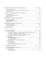
CONTENTS
1 Overview.............................................................................................................. 1 - 1 to 1 - 8
1.1 Connection supported with GOT............................................................................................................1 - 1
2 Specification ...................................................................................................... 2 - 1 to 2 - 20
2.1 PLC CPU that allows monitoring............................................................................................................2 - 1
2.2 Device name that allows monitoring ......................................................................................................2 - 2
2.3 Monitoring of special function unit..........................................................................................................2 - 8
2.4 Access range for monitoring ..................................................................................................................2 - 9
2.4.1 Data link system access range for monitoring when using MELSEC-ACPU and QnACPU .....2 - 9
2.4.2 Network system access range for monitoring when using MELSEC-ACPU and QnACPU ....2 - 11
2.4.3 CC-Link system access range for monitoring when using MELSEC-ACPU and QnACPU ....2 - 19
2.4.4 Access range for monitoring when using MELSEC-FXCPU, other PLC
and microcomputer connections................................................................................................2 - 20
3 Bus connection .................................................................................................. 3 - 1 to 3 - 20
3.1 First step in bus connection....................................................................................................................3 - 1
3.1.1 GOT handling from PLC CPU in bus connection ........................................................................3 - 1
3.1.2 Restriction on the number of GOTs by the PLC CPU connected to...........................................3 - 1
3.1.3 Power supply of PLC CPU and GOT...........................................................................................3 - 2
3.1.4 Restriction when PLC CPU is used in direct method ..................................................................3 - 3
3.1.5 Precautions for use of A1SJCPU and A1SJHCPU .....................................................................3 - 3
3.1.6 Precautions for GOT connection in duplex system .....................................................................3 - 4
3.2 System configuration ..............................................................................................................................3 - 5
3.2.1 System configuration selection procedure...................................................................................3 - 5
3.2.2 Large type CPU/one GOT/within 6.6m between CPU and GOT................................................3 - 6
3.2.3 Large type CPU/one GOT/more than 6.6m between CPU and GOT.........................................3 - 7
3.2.4 Large type CPU/two GOTs/within 6.6m between CPU and first GOT .......................................3 - 8
3.2.5 Large type CPU/two GOTs/more than 6.6m between CPU and first GOT ................................3 - 9
3.2.6 Large type CPU/three GOTs.......................................................................................................3 -10
3.2.7 Small type CPU/one GOT/within 30m between CPU and GOT ................................................3 -11
3.2.8 Small type CPU/one GOT/more than 30m between CPU and GOT.........................................3 -12
3.2.9 Small type CPU/two GOTs/within 5m between CPU and first GOT..........................................3 -13
3.2.10 Small type CPU/two GOTs/more than 5m between CPU and first GOT ................................3 -14
3.2.11 Small type CPU/three GOTs .....................................................................................................3 -15
3.2.12 A0J2HCPU.................................................................................................................................3 -16
3.2.13 Motion controller CPU ...............................................................................................................3 -17
3.3 Switch setting of bus connection board ................................................................................................3 -18
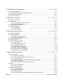
4 Direct connection to CPU .................................................................................... 4 - 1 to 4 - 4
4.1 System configuration of MELSEC-QnA and A connection ...................................................................4 - 1
4.2 System configuration of MELSEC-FX connection.................................................................................4 - 2
5 Computer link connection (RS-422 communication)........................................... 5 - 1 to 5 - 4
5.1 System configuration ..............................................................................................................................5 - 1
5.2 Switch setting of computer link unit and serial communication unit......................................................5 - 2
5.3 Connection cable....................................................................................................................................5 - 4
6 Computer link connection (RS-232C communication)........................................ 6 - 1 to 6 - 6
6.1 System configuration ..............................................................................................................................6 - 1
6.2 Switch setting of computer link unit........................................................................................................6 - 2
6.3 Connection cable....................................................................................................................................6 - 5
7 MELSECNET connection (data link system) ...................................................... 7 - 1 to 7 - 2
7.1 System configuration ..............................................................................................................................7 - 1
7.2 Switch setting of data link unit................................................................................................................7 - 2
7.3 Self-diagnosis test ..................................................................................................................................7 - 2
8 MELSECNET connection (network system) ....................................................... 8 - 1 to 8 - 2
8.1 System configuration ..............................................................................................................................8 - 1
8.2 Switch setting of network unit.................................................................................................................8 - 2
8.3 Self-diagnosis test ..................................................................................................................................8 - 2
9 CC-Link connection ............................................................................................. 9 - 1 to 9 - 2
10 Omron PLC connection ............................................................................... 10 - 1 to 10 - 14
10.1 System configuration..........................................................................................................................10 - 1
10.1.1 System configuration of connection to C200H, C200HS and C200Hα series ....................10 - 1
10.1.2 System configuration of connection to CQM1 ......................................................................10 - 2
10.1.3 System configuration of connection to C1000H and C2000H..............................................10 - 3
10.1.4 System configuration of connection to CV1000....................................................................10 - 3
10.2 Initial setting ........................................................................................................................................10 - 4
10.2.1 Switch setting of upper link unit.............................................................................................10 - 4
10.2.2 Setting CV1000......................................................................................................................10 - 7
10.2.3 Initializing CQM1....................................................................................................................10 - 8
10.2.4 Communication board initialization program.........................................................................10 - 8
10.3 Connection cable................................................................................................................................10 - 9
10.3.1 RS-422 cable .........................................................................................................................10 - 9
10.3.2 RS-232C cable.....................................................................................................................10 - 11
10.3.3 Converter and connection cable used in CQM1.................................................................10 - 13
11 Yasukawa PLC connection ........................................................................... 11 - 1 to 11 - 4
11.1 System configuration..........................................................................................................................11 - 1
11.2 Communication setting of memo bus unit .........................................................................................11 - 2
11.3 Connection cable................................................................................................................................11 - 2
11.3.1 RS-422 cable .........................................................................................................................11 - 2
11.3.2 RS-232C cable......................................................................................................................11 – 3
12 Allen-Bradley PLC connection ...................................................................... 12 - 1 to 12 - 2
12.1 System configuration..........................................................................................................................12 - 1
12.2 Communication settings of Allen-Bradley PLC..................................................................................12 - 1
12.3 Transmission specification .................................................................................................................12 - 2
12.4 Connection cable................................................................................................................................12 - 2
13 Sharp PLC connection ................................................................................. 13 - 1 to 13 -10
13.1 System configuration..........................................................................................................................13 - 1
13.2 Initial setting ........................................................................................................................................13 - 2
13.2.1 Connecting directly to the PLC CPU .....................................................................................13 - 2
13.2.2 Connecting to the link unit .....................................................................................................13 - 4
13.3 Transmission specification .................................................................................................................13 - 5
13.4 Connection cable................................................................................................................................13 - 6
13.4.1 RS-422 cable .........................................................................................................................13 - 6
13.4.2 RS-232C cable.......................................................................................................................13 - 8
14 Microcomputer connection .......................................................................... 14 - 1 to 14 - 14
14.1 System configuration..........................................................................................................................14 - 1
14.2 Connecting cable................................................................................................................................14 - 2
14.2.1 With connection to DTR.........................................................................................................14 - 2
14.2.2 Without connection to DTR....................................................................................................14 - 4
14.3 Transmission specification .................................................................................................................14 - 5
14.4 Device data area ................................................................................................................................14 - 6
14.5 Communication commands ...............................................................................................................14 - 7
14.5.1 Command list .........................................................................................................................14 - 7
14.5.2 Data communication type ......................................................................................................14 - 8
14.5.3 Precautions for use ..............................................................................................................14 - 10
14.5.4 Batch read command(RD)...................................................................................................14 - 11
14.5.5 Batch write command(WD) .................................................................................................14 - 12
14.5.6 Random read command(RR) ..............................................................................................14 - 13
14.5.7 Random write command(RW).............................................................................................14 - 14
15 Option devices connection ........................................................................... 15 - 1 to 15 -18
15.1 Bar code reader ..................................................................................................................................15 - 1
15.1.1 System configuration .............................................................................................................15 - 1
15.1.2 Communication setting of bar code reader...........................................................................15 - 2
15.1.3 Connection cable ...................................................................................................................15 - 3
15.1.4 Recommended parts for customers and ordering method...................................................15 - 4
15.1.5 GOT setting method ..............................................................................................................15 - 5
15.1.6 Bar code types that can be read with GOT...........................................................................15 - 5
15.2 Printer..................................................................................................................................................15 - 6
15.2.1 System configuration .............................................................................................................15 - 6
15.2.2 Connection cable ...................................................................................................................15 - 7
15.3 External I/O equipment.......................................................................................................................15 - 8
15.3.1 System configuration .............................................................................................................15 - 8
15.3.2 Connection cables ................................................................................................................15 -10
15.3.3 Wiring diagrams ....................................................................................................................15 -14
15.3.4 Recommended user-prepared articles and how to prepare them ......................................15 -17
Index ..............................................................................................................Index-1 to Index-2
1. OVERVIEW
MELSEC GOT
Chapter1 Overview
This manual describes the specifications, system configurations, setting method,
connection cables and other information of each connection supported by the GOT.
1.1 Connection supported by GOT
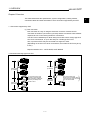
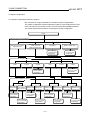
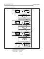
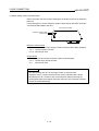
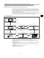
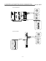
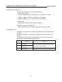
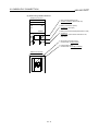
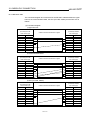
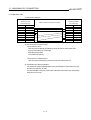
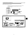
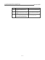
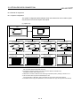
(1) Bus connection
Bus connection is a way of using the extension connector of a base unit for
connection of the GOT (connection by I/O bus) and this connection has the fastest
response to a PLC CPU among the GOT's connections.
The GOT can be installed up to 36.6m away from a base unit for a large type PLC
CPU to be connected to, or up to 35m away for a small type PLC CPU.
Also, up to three GOTs may be connected to a single PLC CPU.
(Depending on the PLC CPU to be connected to, the number of GOTs may be up
to two.)
Required interface unit ... A9GT-BUSS, A9GT-BUS2S
• Connection with large type PLC CPU
• For connection of several GOTs
• For connection of one GOT
MAX. 6.6m
(21.65feet)
MAX. 6.6m
(21.65feet)
MAX. 30m
(98.43feet)
To connect 3 GOT units,
be sure to place the first
GOT unit within a distance
of 6.6m (21.65feet) from
the PLC CPU.
MAX. 30m
(98.43feet)
1-1
A7GT-CNB To place a GOT unit
over 6.6m (21.65feet) away
from the PLC CPU, be sure
to use A7GT-CNB.
1
1. OVERVIEW
MELSEC GOT
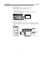
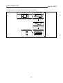
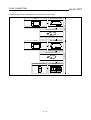
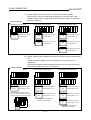
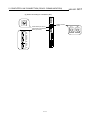
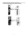
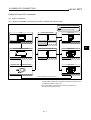
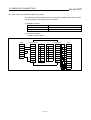
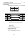
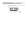
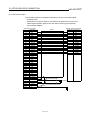
• Connection with small type PLC CPU
• For connection of several GOTs
• For connection of one GOT
MAX. 6m
(19.69feet)
To connect 3 GOT
units, be sure to
place the first GOT
unit within a distance
of 6m (19.69feet)
from the PLC CPU.
MAX. 6m
When the GOT is installed
more than 30m away, the
A7GT-CNB is always
needed.
MAX. 30m
(98.43feet)
MAX. 5m
A7GT-CNB
MAX. 30m
(2) Direct connection to CPU
You can connect the GOT with the MELSEC-A/QnA/FX PLC by an RS-422 cable
and this is the most economical way of connection.
Required interface unit ... A9GT-RS4
(3) Computer link connection
Since the GOT can be connected with a computer link unit on a 1:1 basis, several
GOTs can be connected.
Required interface unit ... A9GT-RS4, A9GT-RS2
1-2
1. OVERVIEW
MELSEC GOT
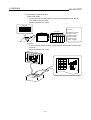
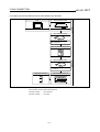
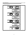
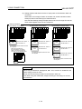
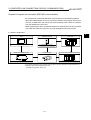
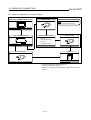
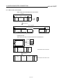
(4) MELSECNET connection
The GOT is used as a local station of the data link system or a normal station of
the network system and allows remote control via network.
Required interface unit : A7GT-J71AP23, A7GT-J71AR23, A7GT-J71AT23B,
A7GT-J71LP23, A7GT-J71BR13
Loop type
Bus type
(5) CC-Link connection
The GOT is used as an intelligent device station or a remote device station of the
CC-Link system and allows remote control via network.
Required interface unit : A8GT-J61BT13, A8GT-J61BT15
Partner manufacturer's product
Remote I/O station
Master station
Intelligent device station/Remote device station
Remote I/O station
Local station
1-3
1. OVERVIEW
MELSEC GOT
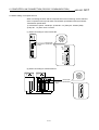
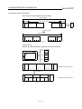
(6) Omron PLC connection
Allows monitoring by connecting to an Omron PLC.
Required interface unit : A9GT-RS4, A9GT-RS2
• CPUs that allow monitoring
C200H, C200HS, C200H, CQM1, C1000H, C2000H, CV1000
RS-422 communication/RS232C communication enables monitoring.
(7) Yasukawa PLC connection
Allows monitoring by connecting to a Yasukawa PLC.
Required interface unit : A9GT-RS4, A9GT-RS2
• CPUs that allow monitoring
GL60S, GL60H, GL70H, GL120, GL130
RS-422 communication/RS232C communication enables monitoring.
(8) Connecting to Allen-Bradley PLC
Monitoring with connection to the Allen-Bradley PLC is now allowed.
Required interface unit : A9GT-RS2
• CPUs that allow monitoring
SLC 5/03, SLC 5/04
Monitored with RS-232C communication
1-4
1. OVERVIEW
MELSEC GOT
(9) Connecting to Sharp PLC
Monitoring with connection to the Sharp PLC is now allowed.
Required interface unit : A9GT-RS4, A9GT-RS2
• CPUs that allow monitoring
JW-21CU, JW-22CU, JW-31CUH, JW-32CUH, JW-33CUH, JW-50CUH,
JW-70CUH, JW-100CUH
Monitored with RS-232C/RS-422 communication
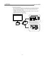
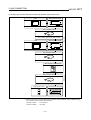
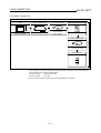
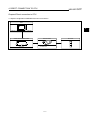
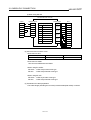
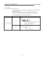
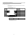
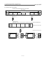
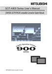
(10)Microcomputer connection
Virtual device (D) of the GOT can be monitored by sending/receiving data from/to
a personal computer, microcomputer board, PLC, etc. (hereinafter referred to as
"host")
Device data area
D0
Memory
D0
D2047
Write/read command
S
E
T RW 0100000A01630362 T D3
X
X
D100 000A
D163 0362
D2047
Interruption output
Microcomputer board
1-5
1. OVERVIEW
MELSEC GOT
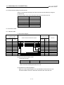
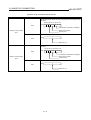
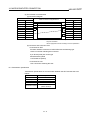
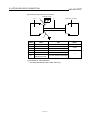
(11)Connecting to optional devices
(a) Bar code reader
If connected to a bar code reader, the GOT can write data read with the bar
code reader to the PLC CPU.
Required interface unit : None
Bar code
Device No.
123456789
PLC CPU
GOT
+0 Number of bytes 9
+1 Data 21 3231H
+2 Data 43 3433H
+3 Data 65 3635H
+4 Data 87 3837H
+5 Data 9 2039H
(b) Printer
If connected to a printer, the GOT can print data of alarm history and hard copy
functions.
Required interface unit : None
9
10
11
12
13
1-6
A-1 A-2
10 15
20 25
30 35
40 45
50 55
1. OVERVIEW
MELSEC GOT
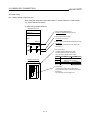
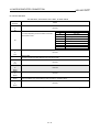
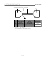
(c) External I/O equipment
By connection of input equipment (operation panel, ten-key panel, pushbuttons,
etc.), you can write to devices, e.g. touch input, numerical input and screen
switching, from outside the GOT.
In addition, you can connect output equipment (lamps, relays, etc.) to provide
outputs from the GOT to the outside.
Required interface unit ... A9GT-70KBF
External input equipment
Operation panel, pushbuttons, etc.
Connector terminal block conversion unit
External output equipment
External I/O unit
Lamp, relay, etc.
1-7
1. OVERVIEW
MELSEC GOT
MEMO
1-8
2. SPECIFICATION
MELSEC GOT
Chapter2 Specification
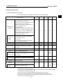
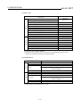
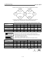
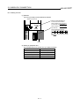
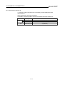
2.1 PLC CPU that allows monitoring
PLC CPUs that allow monitoring are described in the following table.
MELSECNET
Bus
connection connection
Applicable model
MELSEC-A/QnA/
QnASCPU
Computer link unit
that allows
connection
<Large A/QnACPU>
(*1)
QnACPU, Q4ARCPU, Q2ACPU(S1),
Q2AHCPU(S1), AnUCPU, A2UCPU(S1), AnACPU,
A2ACPU(S1), AnNCPU, A2NCPU(S1)
(AnN(S1) must be version L or later with link, and
version H or later without link.)
<Small A/QnASCPU>
Q2ASCPU(S1), Q2ASHCPU(S1), A2USCPU(S1),
A2USHCPU-S1, A1SHCPU, A2SHCPU, A1SCPU,
A2SCPU (version H or later), A1SCPUC24-R2,
A1SJCPU(S3), A1SJHCPU, A0J2HCPU (version E
or later), A2CCPU (version H or later),
A2CCPUC24, A2CJCPU
<For RS-422>
AJ71QC24(R4), AJ71UC24, A1SJ71UC24-R4
A1SJ71QC24,AJ71C24-S8
<For RS-232C>
AJ71QC24(R2), AJ71UC24, A1SJ71QC24(R2),
A1SJ71UC24-R2,A1SJ71C24-R2
A1FXCPU
FA controller
Motion controller
LM610, LM7600, LM8000
A373UCPU, A373UCPU-S3, A273UCPU,
A273UHCPU, A171SCPU-S3, A171SHCPU,
A172SHCPU
MELSEC-FX
FX0, FX0S, FX0N, FX2N, FX2NC, FX1, FX2, FX2C
Omron PLC
C200HS, C200H, C200HX, C200HG, C200HE,
CQM1, C1000H,C2000H,CV1000
Upper link unit that
allows connection
C200H-LK201-V1, C200H-LK202-V1,
C500-LK201-V1, C120-LK201-V1,
C120-LK202-V1
Yasukawa PLC
GL60S, GL60H, GL70H, GL120, GL130
JAMSC-IF60/61, JAMSC-IF612, 120 NOM 271 00
Allen-Bradley PLC
SLC 5/03, SLC 5/04
Link unit that allows
connection
{
{
{
{
{
×
×
{
×
×
×
×
×
{
{
{
{
{
{
×
×
×
×
{
×
×
×
RS-422/
{
×
×
RS-232C
Memo bus unit that
allows connection
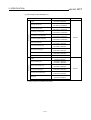
Sharp PLC
2
Computer
CC-Link
CPU direct
link
connection
connection
connection
JW-21CU, JW-22CU, JW-31CUH, JW-32CUH,
JW-33CUH, JW-50CUH, JW-70CUH, JW-100CUH
×
×
×
{
RS-422/
RS-232C
×
×
×
×
×
×
×
RS-422/
JW-21CM, JW-10CM, ZW-10CM
{
RS-232C
×
{
RS-232C
{
RS-232C
• A2CCPU does not allow bus connection or computer link connection.
• A2CCPUC24 does not allow bus connection.
• For computer link connection of A2S/A2S-S1/A2SH-S1/A2SH/A1SH/A1SJH/A171SH/A172SHCPU/A0J2HCPU,
use computer link unit of software version U or later.
Also, the A0J2-C214-S1 (A0J2HCPU-dedicated computer link unit) cannot be used.
• Connection to the remote I/O station cannot be made independently of the connection form.
*1 If the version of CPU is earlier than the one indicated in the parentheses, data cannot be written.
(Bus connection is not related to the version.)
2-1
2. SPECIFICATION
MELSEC GOT
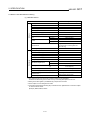
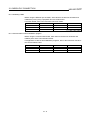
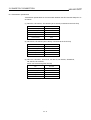
2.2 Device name that allows monitoring
(1) MELSEC-ACPU
Device name
Available range for monitoring
Input (X)
X0 to X1FFF
Output (Y)
Y0 to Y1FFF
Internal relay (M)
M0 to M8191
Annunciator (F)
F0 to F2047
Link relay (B)
B0 to B1FFF
Bit device
Special internal relay (M)
M9000 to M9255
Latch relay (L)
L0 to L8191
Timer
Counter
Contact (TT)
TT0 to TT2047
Coil (TC)
TC0 to TC2047
Contact (CT)
CT0 to CT1023
Coil (CC)
CC0 to CC1023
Designated bit of the following word
devices (except for index register and
buffer memory)
Word device bit
GOT bit register (GB)
GB64 to GB1023
Data register (D)
D0 to D8191
Special data register (D)
D9000 to D9255
Link register (W)
W0 to W1FFF
Word device
Timer (current value) (T)
T0 to T2047
Counter (current value) (C)
C0 to C1023
File register (R)
R0 to R8191
Extended file register (ER)
Index register *2
Block
1 to 255
Device
R0 to R8191
(Z)
Z0 to Z6(Z0=Z)
(V)
V0 to V6(V0=V)
Accumulator (A)
A0 to A1
Buffer memory (special function unit) (BM)
BM0 to BMn*1
Converting the above bit devices to words
(except for timer and counter)
Bit device word *3 *4
GOT data register (GD)
GD64 to GD1023
*1 Only special function units of the GOT connection station can be designated.
Set within the address range of the buffer memory of the designated special function unit.
*2 Writing to the index register is prohibited during computer link connection.
*3 Use a multiple of 16 for setting device number.
*4 If converting the special internal relay (M) to a bit device word, regard 9000 as 0 and use a multiple
of 16 for the device number.
(Example) M9000, M9016, M9240
2-2
2. SPECIFICATION
MELSEC GOT
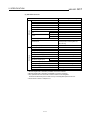
(2) MELSEC-QnACPU
Device name
Allowable range of monitoring
Input (X)
X0 to X1FFF
Output (Y)
Y0 to Y1FFF
Internal relay (M)
M0 to M32767
Latch relay (L)
L0 to L32767
Annunciator (F)
F0 to F32767
Bit device
Link relay (B)
B0 to B1FFF
Timer
Counter
Contact (TT)
TT0 to TT32767
Coil (TC)
TC0 to TC32767
Contact (CT)
CT0 to CT32767
Coil (CC)
CC0 to CC32767
Special relay (SM)
SM0 to SM2047
Designated bit of the following word
devices (except for index register and
buffer memory)
Word device bit
GOT bit register (GB)
GB64 to GB1023
Data register (D)
D0 to D32767
Special data register (SD)
SD0 to SD2047
Word device
Link register (W)
W0 to W1FFF
Timer (current value) (T)
T0 to T32767
Counter (current value) (C)
C0 to C32767
1
File register (R)
R0 to R32767*
Extended file register (ER)
Block
Device
Extended file register (ZR)
0 to 31
R0 to R32767
ZR0 to ZR1042431*2
Index register (Z)
Z0 to Z15
Buffer memory (special function unit) (BM)
Bit device word *4
BM0 to BMn*3
Converting the above bit devices to words
GOT data register (GD)
GD64 to GD1023
*1 Block file register that is switched by the RSET command is monitored.
*2 Block file register that is switched by the QFRSET command is monitored.
*3 Only special function units of the GOT connection station can be designated.
Set within the address range of the buffer memory of the designated special function unit.
*4 Set the device numbers in multiples of 16.
2-3
2. SPECIFICATION
MELSEC GOT
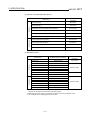
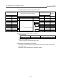
(3) CC-Link connection (Remote device)
Available range for
monitoring
Word device
Bit device
Device name
Remove input (RX)
X0 to X7FF
Remote output (RY)
Y0 to Y7FF
Bit designation of remote register write area (RWw)
Ww0 to WwFF
Bit designation of remote register read area (RWr)
Wr0 to WrFF
GOT bit register (GB)
GB64 to GB1023
Bit designation of GOT data register (GD)
GD64 to GD1023
Remote register write area (RWw)
Ww0 to WwFF
Remote register read area (RWr)
Wr0 to WrFF
GOT data register (GD)
GD64 to GD1023
Converting GOT bit register to word (GB)
GB64 to GB1023
(4) MELSEC-FXCPU
Bit device
Device name
Available range for monitoring
Input relay (X)
X0000 to X0377
Output relay (Y)
Y0000 to Y0377
Auxiliary relay (M)
M0000 to M3071
State (S)
S0000 to S0999
Special auxiliary relay (M)
M8000 to M8255
Timer contact (T)
T000 to T255
Counter contact (C)
C000 to C255
Word device bit *1
Word device
GOT bit register (GB)
GB64 to GB1023
Timer (current value) (T)
T000 to T255
Counter (current value) (C)
C000 to C255
Data register (D)
D000 to D0999
RAM file register (D)
D1000 to D7999
Special data register (D)
D8000 to D8255
Device number
expression
Octal notation
Decimal notation
Decimal notation
Bit device word *2 *3
GOT data register (GD)
GD64 to GD1023
*1 While the touch key function to which a word device bit is designated as the monitor device is
executed, do not write the word device in a sequence program.
*2 Bit devices of the timer contact (T) and counter contact (C) cannot be converted to words.
*3 Use a multiple of 16 for designating the device number.
2-4
2. SPECIFICATION
MELSEC GOT
(5) Omron PLC
Available range for
monitoring
Device name
I/O relay
..0000 to 51115
Bit device
Internal auxiliary relay
Data link relay (LR)
LR0000 to LR6315
Auxiliary memory relay (AR)
AR0000 to AR2715
Holding relay (HR)
HR0000 to HR9915
Timer contact (TIM) *1
TIM000 to TIM511
Counter contact (CNT) *1
CNT000 to CNT511
Data memory (DM) *2
DM0000 to DM9999
2
Timer (current value) (TIM) *
TIM000 to TIM511
Counter (current value) (CNT) *2
CNT000 to CNT511
GOT bit register
GB64 to GB1023
..000 to 511
I/O relay
Word device
Data link relay (LR)
LR0000 to LR0063
Auxiliary memory relay (AR)
AR0000 to AR0027
Holding relay (HR)
HR0000 to HR0099
Data memory (DM)
DM0000 to DM9999
Timer (current value) (TIM)
TIM000 to TIM511
Counter (current value) (CNT)
CNT000 to CNT511
GOT data register
GD64 to GD1023
*1 If CV1000 is used, no writing is available.
*2 While the touch key function to which a word device bit is designated as the monitor device is
executed, do not write the word device in a sequence program.
(6) Yasukawa PLC
Device name
Available range for monitoring
Bit device
Coil
O01 to O63424
Input relay
I1 to I63424
D1 to D2048
Link coil
D10001 to D12048
D20001 to D22048
GOT bit register
GB64 to GB1023
Word device
Input register
Z1 to Z31840
Holding register
W1 to W28291
R1 to R2048
Link register
R10001 to R12048
R20001 to R22048
1
Constant register
K1 to K4096*
GOT data register
GD64 to GD1023
*1 Change range 31000 to 35096 to range 1 to 4096.
2-5
2. SPECIFICATION
MELSEC GOT
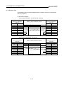
(7) Connecting to Allen-Bradley PLC
Device name
Monitoring range
B0030000 to B003255F
B0100000 to B255255F
Word device
Bit (B)
Timer (timing bit) (TT)
TT0040000 to TT0042550
TT0100000 to TT2552550
Timer (timing bit) (TN)
TN0040000 to TN0042550
TN0100000 to TN2552550
Counter (up counter) (CU)
CU0050000 to CU0052550
CU0100000 to CU2552550
Counter (down counter) (CD)
CD0050000 to CD0052550
CD0100000 to CD2552550
Counter (completion bit) (CN)
CN0050000 to CN0052550
CN0100000 to CN2552550
Decimal
Timer (set value) (TP)
TP004000 to TP004255
TP010000 to TP255255
*1
Timer (current value) (TA)
TA004000 to TA255255
TA010000 to TA255255
*1
Counter (set value) (CP)
CP004000 to CP255255
CP010000 to CP255255
*1
Counter (current value) (CA)
CA005000 to CA005255
CA010000 to CA255255
*1
GOT internal bit register (GB)
GB64 to GB1023
B003000 to B003255
B010000 to B255255
Bit (B)
Bit device
Device No. notation
Timer (set value) (TP)
TP004000 to TP004255
TP010000 to TP255255
*1
Timer (current value) (TA)
TA004000 to TA255255
TA010000 to TA255255
*1
Counter (set value) (CP)
CP004000 to CP255255
CP010000 to CP255255
*1
Counter (current value) (CA)
CA005000 to CA005255
CA010000 to CA255255
*1
N007000 to N007255
N010000 to N255255
Integer (N)
GOT internal data register (GD)
*1 Writing on device is not allowed for 32 bit data.
2-6
GD64 to GD1023
Decimal
2. SPECIFICATION
MELSEC GOT
(8) Connecting to Sharp PLC
Device name
Setting monitor
Device No. notation
0 to 15777
20000 to 75777
I/O relay
Timer counter (contact)
T/C0000 to T/C1777
Timer counter (current value)
T/C0000 to T/C1777
(b0000 to b3776)
09000 to 09776
19000 to 19776
29000 to 29776
39000 to 39776
49000 to 49776
59000 to 59776
69000 to 69776
79000 to 79776
89000 to 89776
99000 to 99776
E0000 to E0776
E1000 to E1776
E2000 to E2776
E3000 to E3776
E4000 to E4776
E5000 to E5776
E6000 to E6776
E7000 to E7776
Register
1000000 to 1177776
2000000 to 2177776
3000000 to 3177776
4000000 to 4177776
5000000 to 5177776
6000000 to 6177776
7000000 to 7177776
File register
2-7
Octal
2. SPECIFICATION
MELSEC GOT
Bit device
(9) Microcomputer connection
Device name
Available range for monitoring
GOT bit register (GB)
GB64 to GB1023*1
Data register (D)
D0 to D2047
Word device
Bit designation of word
device (C)
*1
Data register (D)
D0 to D2047
GD64 to GD1023*1
GOT data register (GD)
*1 Writing and reading operations are not available from the host to devices GB and GD.
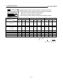
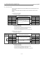
2.3 Monitoring of special function unit
Monitoring of special function unit is limited to the following stations.
(1) When using bus connection/CPU direct connection/Computer link connection
Special function unit on the base of the connected station
(2) When using MELSECNET (II) connection/MELSECNET/B connection
Special function unit on the base of the master station
(3) When using MELSECNET/10 connection
Special function unit on the base of the control and normal stations
(4) When using CC-Link connection (Intelligent device station)
Special function unit on the base of the master and local stations
2-8
2. SPECIFICATION
MELSEC GOT
2.4 Access range for monitoring
POINT
It should be noted that you cannot connect the GOT to monitor a remote I/O
station in a network system or data link system.
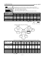
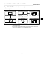
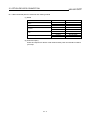
2.4.1 Data link system access range for monitoring when using MELSEC-ACPU and QnACPU
(1) Bus connection/CPU direct connection/Computer link connection
(a) If connected to master station
• Local stations can be monitored. If
the PLC CPU of the local station is
M
QnACPU, devices other than B and
L3
L1
W that are allocated by the link
parameter cannot be monitored.
L2
(b) If connected to local station
• The master station can be monitored.
If the PLC CPU of the local station is
QnACPU, devices other than B and
L1
W that are allocated by the link
parameter cannot be monitored.
• Other local stations cannot be
monitored.
(c) If connected to the master station on the third layer
• The master station on the second
layer and local stations on the third
layer can be monitored. If the PLC
L1
CPU of the local station is QnACPU,
devices other than B and W that are
allocated by the link parameter
1
cannot be monitored.
• Local stations on the second layer
cannot be monitored.
M
L3
L2
GOT
M
L3
L2
m
GOT
3
2
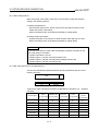
(2) MELSECNET/B connection and MELSECNET(II) connection
• The GOT is regarded as a local station
M
and can monitor only the master
L1
station. If the PLC CPU of the local
station is QnACPU, devices other than
GOT
B and W that are allocated by the link
L2
parameter cannot be monitored.
• Local devices cannot be monitored.
When setting the monitor device,
designate the NW number and the
POINT
station number as follows.
For monitoring devices B
When monitoring devices B and W that
and W that are allocated
by the link parameter,
are allocated by the link parameter :
make sure to use the local
device number if
NW number : 0, Station number : Local
designating devices
allocated to other station.
When monitoring devices other than B
If not, display speed will
be reduced.
and W of the master station :
NW number : 0, Station number :
Others (Station number : 0)
2-9
GOT
L3
2. SPECIFICATION
MELSEC GOT
(3) Monitoring devices of other stations
If other devices on the data link system are monitored, display speed will be
significantly reduced. Therefore monitor link relay (B) and link register (W) that are
allocated by the link parameter.
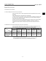
(4) Setting method of monitor device
Describes the NW numbers for setting monitor devices and method of setting
station numbers with an example shown below.
M
L1
L3
L2
m
1
GOT
3
2
POINT
For monitoring devices B
and W that are allocated
by the link parameter,
make sure to use the local
device number if
designating devices
allocated to other station.
If not, display speed will
be reduced.
(a) When monitoring devices B and W that are allocated by the connected station
(local station) and link parameter :
NW number : 0, Station number : Local
(b) When monitoring devices of other stations :
NW number : 0, Station number : Refer to the following table.
Station number setting
Station to be
accessed
Station
connected to
GOT
M
L1
L2
m
L3
1
2
3
M
Local
Other 1
Other 2
Other 3
L1
Other 0
Local
L2
m
Other 0
Local
Other 1
Other 2
L3
Other 0
Local
1
Other 0
Local
2
Other 0
Local
3(GOT)
Other 0
2 - 10
2. SPECIFICATION
MELSEC GOT
2.4.2 Network system access range for monitoring when using MELSEC-ACPU and QnACPU
(1) Bus connection
(a) If connected to QnACPU/AnUCPU
1) The control station on the network and all normal stations can be monitored.
2) The control station on the other network and all normal stations can be
monitored.
(To monitor the other network, be sure to designate the routing parameter.)
3) If connected to an intermediate station and the data link system is included,
the master station and local stations can be monitored.
4) If connected to an intermediate station, it is not necessary to designate the
data link parameter "Effective unit number for accessing other stations" for
the PLC CPU of the connected station. (If designated, the parameter will be
ignored.)
5) Devices of other stations (other than devices B and W that are allocated by
the network parameter) may not allow monitoring depending on their PLC
CPU.
Refer to Examples 1 to 4.in (7).
(b) If connected to AnA and AnNCPU
1) Control stations on the network can be monitored.
If the PLC CPU of the local station is QnACPU, devices other than B and W
that are allocated by the network parameter cannot be monitored.
2) Normal stations on the network cannot be monitored.
3) Stations on the other network cannot be monitored.
(2) CPU direct connection/computer link connection
(a) If connected to QnACPU
1) Access range is as described in (1) (a).
(b) If connected to AnUCPU
1) Control station on the network and all normal stations can be monitored.
When devices of other stations (other than devices B and W that are
allocated by the network parameter) are monitored, monitoring is not
available if the PLC CPU to be monitored is QnACPU.
2) If connected to an intermediate station, use data link parameter "Effective
unit number to access other stations" to designate the unit number that is
connected to the network to be monitored.
(c) If connected to AnA, AnNCPU
1) Control stations on the network can be monitored.
If the PLC CPU of the control station is AnACPU, devices other than B and
W that are allocated by the network parameter cannot be monitored.
2) Normal stations on the network cannot be monitored.
3) The other network cannot be monitored.
(3) CC-Link connection (intelligent device station)
• Connected stations can be monitored.
• Other stations on the network system cannot be monitored.
2 - 11
2. SPECIFICATION
MELSEC GOT
(4) MELSECNET/10 connection
(a) The GOT is regarded as a normal station. The control station on the network
and all normal stations can be monitored.
If the PLC CPU to be monitored is QnACPU, monitoring is available within the
device access range for AnA. (The access range for monitoring of timer (T) and
counter (C) is limited to 0 to 225. File registers (R, ER, ZR) cannot be
monitored.)
(b) The other network cannot be monitored.
(c) If devices of other stations (other than devices B and W that are allocated by
the network parameter) are monitored, monitoring may not be available
depending on the PLC CPU of the network system to be monitored. Refer to
(Example 6).
(5) Monitoring devices of other stations on network
If devices of other stations on the network system are monitored, display speed will
be significantly reduced. Therefore monitor link relay (B) and link register (W) that
are allocated by the network parameter.
(6) Monitoring devices of the other network
(a) Be sure to designate the routing parameter to the PLC CPU of the connected
station.
(b) If the other network is monitored, display speed of sprite etc. will be significantly
reduced.
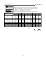
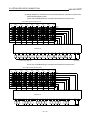
(7) Monitor access range of other stations and setting method of monitor devices
(Example 1) When using bus connection
QnA
(1-2)
Control station
Control station
AnU
(1-1)
QnA
(2-1)
Network No.1
AnU
(1-4)
(2-2)
AnU
(2-4)
Network No.2
AnA
(1-3)
AnN
(2-3)
• Monitor access range of other station devices (other than B and W)/other network
Station to be
accessed
Station
connected to GOT
AnU (1-1)
QnA (1-2)
AnA (1-3)
AnU
(1-4)
(2-2)
QnA (2-1)
AnN (2-3)
AnU (2-4)
Network No.1
AnU (1-1)
{ Local
{
{
{
{
×
{
QnA (1-2)
Network No.2
AnA (1-3)
×
{
×
{ Local
×
×
{
×
×
×
{ Local
×
×
×
2 - 12
AnU (1-4)
{
{
×
{ Local
{
×
{
QnA (2-1)
×
{
×
×
{ Local
×
×
AnU (2-2)
AnN (2-3)
AnU (2-4)
×
×
×
×
{
{
×
×
{
{
{
{
{ Local
{
×
{
{ : Accessible
{
{ Local
×
×
{ Local
× : Not accessible
2. SPECIFICATION
MELSEC GOT
POINT
For monitoring devices B
and W that are allocated
by the network parameter,
make sure to use the local
device number if
designating devices
allocated to other station.
If not, display speed will
be reduced.
Station to be
accessed
Station
connected to GOT
• Designating NW number and station number for setting monitor device
1) Monitoring devices B and W that are allocated by the network parameter at
the connected station (local station)
NW number: 0, Station number: Local
2) When monitoring other stations (other than B and W)/other network
Network No.1
Network No.2
AnU (1-1)
QnA (1-2)
AnA (1-3)
AnU (1-4)
QnA (2-1)
AnU (2-2)
AnU (1-1)
0, Local
1, Other (3)
1, Other (4)
2, Other (2)
QnA (1-2)
1, Other (1)
0, Local
1, Other (4)
2, Other (1)
2, Other (2)
AnA (1-3)
0, Other (0)
0, Local
1, Other (1)
0, Local
0, Local
2, Other (4)
QnA (2-1)
1, Other (1)
1, Other (2)
1, Other (4)
0, Local
2, Other (2)
2, Other (3)
2, Other (4)
AnN (2-3)
0, Local
1, Other (1)
AnU (2-4)
AnU
(1-4)
(2-2)
1, Other (4)
AnN (2-3)
AnU (2-4)
2, Other (4)
2, Other (4)
2, Other (2)
How to read the
table
0, Local
2,
Other (2)
↑
NW number
↑
Station number
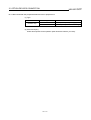
(Example 2) When using bus connection
Control station
Control station
QnA
(1-1)
AnU
(2-1)
Network No.1
AnA
(1-2)
AnU
(2-4)
Network No.2
QnA
(1-3)
(2-2)
(M)
GOT
(2-3)
Data link system
AnA
(L2)
QnA
(L1)
• Monitor access range of other station devices (other than B and W)/other network
Station
connected to
GOT
Station to be
accessed
Network No.1
QnA
(1-1)
QnA (1-1)
AnA (1-2)
(1-3)
QnA (2-2)
(M)
AnU (2-1)
GOT (2-3)
AnU (2-4)
QnA (L1)
AnA (L2)
AnA
(1-2)
Network No.2
QnA
(1-3)
AnU
(2-1)
QnA
(2-2)
GOT
(2-3)
×
×
×
{ Local
×
{
{ Local
{
×
{ Local
{
{ Local
×
×
×
×
×
×
×
×
×
×
×
×
×
×
×
{ Local
{
{
×
{ : Accessible
× : Not accessible
{
{
×
×
{
×
×
×
Data link system
AnU
(2-4)
QnA
(M)
QnA
(L1)
AnA
(L2)
×
×
×
×
×
×
{
{ Local
×
{
{
{
×
×
×
×
×
×
×
×
{
{ Local
×
×
{
×
×
×
{ Local
×
{ Local
: Accessible within the range for AnA (T/C: 0 to 255, R/ER/ZR cannot be monitored)
2 - 13
2. SPECIFICATION
POINT
For monitoring devices B
and W that are allocated
by the network parameter,
make sure to use the local
device number if
designating devices
allocated to other station.
If not, display speed will
be reduced.
Station
connected to
GOT
MELSEC GOT
• Designating NW number and station number for setting monitor device
1) When monitoring devices B and W that are allocated by the network
parameter at the connected station (local station)
NW number: 0, Station number: Local station
2) When monitoring other stations (other than B and W)/other network
Station to be
accessed
Network No.1
QnA
(1-1)
AnA
(1-2)
Network No.2
QnA
(1-3)
AnU
(2-1)
QnA
(2-2)
Data link system
GOT
(2-3)
AnU
(2-4)
2, Other (4)
QnA
(M)
QnA
(L1)
AnA
(L2)
1, Other (3)
QnA (1-1)
0, Local
1, Other (2) 1, Other (3) 2, Other (1) 2, Other (2)
or
2, Other (2)
AnA (1-2)
0, Local
0, Local
1, Other (1)
0, Local
2, Other (1)
2, Other (4)
0, Local
0, Local
2, Other (4)
0, Other (4) 0, Other (2)
(1-3)
QnA (2-2)
(M)
AnU (2-1)
GOT (2-3)
0, Other (1) 0, Other (2)
AnU (2-4)
2, Other (1)
0, Local
QnA (L1)
AnA (L2)
0, Other (2)
*1
0, Local
0, Local
*1 When monitoring the data link system, designate the NW number as 0.
How to read the
table
2 - 14
2,
Other (2)
↑
NW number
↑
Station number
2. SPECIFICATION
MELSEC GOT
(Example 3) When using CPU direct connection or computer link connection
QnA
(1-2)
Control station
Control station
AnU
(1-1)
QnA
(2-1)
Network No. 1
AnU
(1-4) *1
(2-2)
AnU
(2-4)
Network No. 2
AnA
(1-3)
AnN
(2-3)
*1 Data link parameter "Effective unit number for accessing other stations" is
designated to the unit number that is connected to the network No. 1.
• Monitor access range of other station devices (other than B and W)/other network
Station to be
accessed
Station
connected to GOT
{ Local
{
{
{
{
AnU (1-1)
QnA (1-2)
AnA (1-3)
AnU
(1-4)
(2-2)
QnA (2-1)
×
×
AnN (2-3)
AnU (2-4)
POINT
For monitoring devices B
and W that are allocated
by the network parameter,
make sure to use the local
device number if
designating devices
allocated to other station.
If not, display speed will
be reduced.
Station to be
accessed
Station
connected to GOT
Network No.1
AnU (1-1)
QnA (1-2)
Network No.2
AnA (1-3)
×
{
×
{ Local
×
×
{
×
×
×
{ Local
×
×
×
AnU (1-4)
{
{
×
{ Local
{
×
×
QnA (2-1)
×
{
×
×
{ Local
×
×
AnU (2-2)
AnN (2-3)
AnU (2-4)
×
×
×
×
{
×
×
{
{ Local
{
{
{
{ Local
{
×
{
Network No.1
AnU (1-4)
QnA (2-1)
AnU (2-2)
AnU (1-1)
0, Local
0, Other (3)
0, Other (4)
0, Other (4)
QnA (1-2)
1, Other (1)
0, Local
1, Other (4)
2, Other (1)
2, Other (2)
AnA (1-3)
0, Other (0)
0, Local
0, Other (1)
0, Local
1, Other (1)
1, Other (2)
QnA (2-1)
AnN (2-3)
AnU (2-4)
× : Not accessible
Network No.2
AnA (1-3)
(2-2)
×
{ Local
• Designating NW number and station number for setting monitor device
1) Monitoring devices B and W that are allocated by the network parameter at
the connected station (local station)
NW number: 0, Station number: Local
2) When monitoring other stations (other than B and W)/other network
QnA (1-2)
AnU
×
×
{ : Accessible
AnU (1-1)
(1-4)
×
AnN (2-3)
AnU (2-4)
2, Other (4)
0, Local
1, Other (4)
0, Local
2, Other (2)
2, Other (3)
2, Other (4)
0, Local
How to read the
table
2 - 15
0, Other (2)
0, Local
2,
Other (2)
↑
NW number
↑
Station number
2. SPECIFICATION
MELSEC GOT
(Example 4) When using CPU direct connection or computer link connection
Control station
Control station
QnA
(1-1)
AnU
(2-1)
Network No. 1
Network No. 2
QnA
(1-3)
(2-2)
(M)
AnA
(1-2)
AnU
(2-4)
GOT
(2-3)
Data link system
AnA
(L2)
QnA
(L1)
• Monitor access range of other station devices (other than B and W)/other network
Station
connected to
GOT
Station to be
accessed
Network No.1
QnA
(1-1)
QnA (1-1)
AnA (1-2)
(1-3)
QnA (2-2)
(M)
AnU (2-1)
GOT (2-3)
AnU (2-4)
QnA (L1)
AnA (L2)
{ Local
AnA
(1-2)
{
Network No.2
QnA
(1-3)
{
×
{ Local
{
×
{ Local
×
×
×
×
×
×
×
×
×
×
×
×
×
×
×
{ : Accessible
× : Not accessible
×
AnU
(2-1)
{
×
QnA
(2-2)
{
GOT
(2-3)
×
{
{ Local
{ Local
{
{
×
×
×
×
×
×
Data link system
AnU
(2-4)
QnA
(M)
QnA
(L1)
AnA
(L2)
×
×
×
×
×
{
{ Local
×
{
{
{
×
×
×
×
×
×
×
×
{
×
{ Local
×
×
{
×
×
×
{ Local
×
{ Local
: Accessible within the range for AnA (T/C: 0 to 255, R/ER/ZR cannot be monitored)
2 - 16
2. SPECIFICATION
MELSEC GOT
POINT
For monitoring devices B
and W that are allocated
by the network parameter,
make sure to use the local
device number if
designating devices
allocated to other station.
If not, display speed will
be reduced.
Station to be
accessed
Station
connected to
GOT
QnA
(1-1)
QnA (1-1)
0, Local
• Designating NW number and station number for setting monitor device
1) When monitoring devices B and W that are allocated by the network
parameter at the connected station (local station)
NW number: 0, Station number: Local station
2) When monitoring other stations (other than B and W)/other network
Network No.1
AnA
(1-2)
Network No.2
QnA
(1-3)
AnU
(2-1)
QnA
(2-2)
Data link system
GOT
(2-3)
AnU
(2-4)
2, Other (4)
QnA
(M)
QnA
(L1)
AnA
(L2)
1, Other (3)
1, Other (2) 1, Other (3) 2, Other (1) 2, Other (2)
or
2, Other (2)
AnA (1-2)
0, Local
1, Other (1)
0, Local
2, Other (1)
0, Local
2, Other (4)
0, Local
0, Local
2, Other (4)
0, Other (4) 0, Other (2)
(1-3)
QnA (2-2)
(M)
AnU (2-1)
GOT (2-3)
0, Other (1) 0, Other (2)
AnU (2-4)
2, Other (1)
0, Local
QnA (L1)
AnA (L2)
0, Other (2)
*1
0, Local
0, Local
*1 When monitoring the data link system, designate the NW number as 0.
How to read the
table
2 - 17
2,
Other (2)
↑
NW number
↑
Station number
2. SPECIFICATION
MELSEC GOT
(Example 5) When using MELSECNET/10 connection
QnA
(1-1)
QnA
(1-2)
AnU
(1-4)
When using MELSECNET/10 connection,
the other network cannot be monitored.
GOT
(1-3)
• Monitor access range for other station devices (other than B and W)
Station
connected
to GOT
Station to be
accessed
QnA
(1-1)
QnA
(1-2)
GOT
(1-3)
GOT (1-3)
AnU
(1-4)
{
{ : Accessible
: Accessible within the range
of AnA
(T/C: 0 to 255, R/ER/ZR
cannot be monitored.)
× : Not accessible
POINT
For monitoring devices B
and W that are allocated
by the network parameter,
make sure to use the local
device number if
designating devices
allocated to other station.
If not, display speed will
be reduced.
y Designating NW number and station number for setting monitor device
1) Monitoring devices B and W that are allocated by network parameter
NW number: 0, Station number: Local
2) Monitoring other stations (other than B and W)
Station
connected
to GOT
Station to be
accessed
GOT (1-3)
QnA
(1-1)
QnA
(1-2)
GOT
(1-3)
AnU
(1-4)
0, Other (1)
0, Other (2)
0, Other (4)
How to read the table 0,
Other (2)
NW number Station number
(Example 6) When using CC-Link connection (intelligent device station)
AnU
(1-2)
QnA
(1-1)
AnA
(1-3)
AnN
(1-4)
Station
connected
to GOT
QnA (1-1)
AnU (1-2)
AnA (1-3)
AnN (1-4)
Station to be
accessed
QnA
(1-1)
×
×
×
×
AnU
(1-2)
AnA
(1-3)
AnN
(1-4)
×
×
×
×
×
×
{
×
×
2 - 18
{
×
{
{: Accessible
× : Not accessible
2. SPECIFICATION
MELSEC GOT
2.4.3 CC-Link system access range for monitoring when using MELSEC-ACPU and QnACPU
(1) When using Bus connection/CPU direct connection/computer link connection
Only connected stations can be monitored.
(2) When using CC-link connection (remote device station)
(a) Access range
Devices RX, RY, RWw, RWr for which the GOT is allocated to the master
station by setting the CC-Link parameter and the internal device of the GOT
can be monitored.
Other devices RX, RY, RWw, RWr allocated to the master station cannot be
monitored.
(b) Designating NW number and station number
Be sure to designate as follows.
NW number:0, Station number: Local
(c) Designating device name and device number
Use the following device names.
For devices RX, RY, RWw and RWr, designate the addresses allocated by
station number setting.
Device name to be set by
drawing software
Device to be monitored
Device setting range
Remote input
RX
X
X0 to X7FF
Remote output
RY
Y
Y0 to Y7FF
Ww0 to WwFF
Remote register (writing area)
RWw
Ww
Remote register (reading area)
RWr
Wr
Wr0 to WrFF
GOT internal bit device
GB
GB
GB0 to GB1023
GOT internal word device
GD
GD
GD0 to GD1023
2 - 19
2. SPECIFICATION
MELSEC GOT
(3) When using CC-Link connection (intelligent device station)
(a) Access range
Master station/local station can be monitored.
By setting CC-Link parameter, all devices RX, RY, RWw and RWr that are
allocated to the master station can be monitored.
POINT
For monitoring devices
RX, RY, RWw and RWr
that are allocated
by setting CC-Link parameter,
make sure to use the local
device number if
designating devices
allocated to other station.
If not, display speed will
be reduced.
(b) Setting NW number and station number
1) When monitoring devices RX, RY, RWw and RWr that are allocated to the
master station by setting CC-Link parameter
NW number: 0, PLC station number: Local
2) When monitoring PLC CPU devices of other station
NW number: 0, PLC station number: Other (Station number: n)
(n: Station number of other station you want to monitor (0: Master station, 164: Local station))
(c) Setting device name and device number
1) Monitoring devices RX, RY, RWw and RWr that are allocated by setting CCLink parameter
Use the following device names.
For devices RX, RY, RWw and RWr, designate the addresses allocated by
station number setting.
Device name to be set by
drawing software
Device to be monitored
Device setting range
Remote input
RX
X
X0 to X7FF
Remote output
RY
Y
Y0 to Y7FF
Remote register (writing area)
RWw
Ww
Ww0 to WwFF
Remote register (reading area)
RWr
Wr
Wr0 to WrFF
2) Monitoring PLC CPU devices of other stations
For device name and device number, refer to 2.2.
2.4.4 Access range for monitoring when using MELSEC-FXCPU, other PLC and microcomputer connections
Only the connected CPU can be monitored. Other stations cannot be monitored.
2 - 20
3. BUS CONNECTION
MELSEC GOT
Chapter3 Bus connection
3.1 First step in bus connection
3.1.1 GOT handling from PLC CPU in bus connection
In bus connection, the PLC CPU recognizes the GOT as a special function unit of 32
I/O points.
When setting the GOT, it cannot be set on a main base.
The GOT can be set in a location of empty points within the maximum I/O points of the
PLC CPU used, excluding those of the main base. (It is recommended to assign the
GOT after the unit's last I/O number.)
However, if the PLC CPU has empty points, the GOT cannot be set in such a location
when the PLC CPU used is the Q3ACPU, Q4A(R)CPU, A3 CPU, A4UCPU or
A0J2HCPU and all I/O slots on all bases of up to the seventh extension base are
used.
3.1.2 Restriction on the number of GOTs by the PLC CPU connected to
In bus connection, note that the number of GOTs connected is restricted by the PLC
CPU connected to and the number of special function modules loaded.
MELSEC-QnACPU/MELSEC-ACPU
Motion Controller CPU
QnA(R)CPU,
QnAS(H)CPU
AnUCPU,
AnACPU,
A2US(H)CPU
A0J2HCPU
CPU not
given at left
A273U(H)CPU,
A373UCPU
CPU not
given at left
Number of connectable
GOTs
Max. 3
Max. 3
Max. 1
Max. 2
Max. 3
Max. 2
Total number of GOTs
and special function
1
units* loadable
6 in all
6 in all
2 in all
2 in all
6 in all
2 in all
*1 Indicate the following types of special function units.
AD51(S3), AD51H(S3), AD51FD(S3), AD57G(S3), AJ71C21(S1), AJ71C22(S1), AJ71C23,
AJ71C24(S3/S6/S8), AJ71E71, AJ71UC24, A1SJ71UC24(R2/PRF/R4), A1SJ71E71
3-1
3
3. BUS CONNECTION
MELSEC GOT
3.1.3 Power supply of PLC CPU and GOT
Note the following when supplying power to the PLC CPU and GOT.
! CAUTION
• To prevent trouble from occurring, the extension cable which connects the
PLC CPU and GOT should be unplugged when the PLC CPU and GOT are
off.
(1) Switch on the PLC CPU and GOT in either of the following methods. When several
GOTs are connected, either of the following methods should be used.
(a) Switch on the PLC CPU and GOT at the same time.
(b) Switch on the PLC CPU and GOT in this order.
When several GOTs are connected, there is no specific sequence of switching
on the GOTs.
(2) When you switch power on in the above method (b), switching on the GOT runs
the PLC CPU.
When several GOTs are connected, switching on all GOTs runs the PLC CPU.
(3) When the PLC CPU and GOT are on, switching off the PLC CPU will cause a
communication error to occur in the GOT.
When a communication error has occurred, switch off the GOT and switch on the
PLC CPU and GOT in the method in above (1).
(4) If the GOT is switched off during monitoring, the PLC CPU continues running.
(5) With the PLC CPU on, the bus connection board of the GOT is supplied with a
consumptive current (220mA) from the PLC CPU, independently of whether the
GOT unit is on or off. Therefore, design the system so that the sum of the 5VDC
consumptive currents of the I/O and special function units loaded on the base unit
and the consumptive current (220mA) of the bus connection board of the GOT will
not exceed the 5VDC rated output current (8A) of the power supply unit.
POINT
The consumptive current will increase as indicated below according to the
number of GOTs connected.
Connection of one GOT ............ Consumptive current (220mA)
Connection of two GOTs........... Consumptive current (440mA)
Connection of three GOTs ........ Consumptive current (660mA)
3-2
3. BUS CONNECTION
MELSEC GOT
3.1.4 Restriction when PLC CPU is used in direct method
Note that the inputs X of the empty slots cannot be used when the I/O control system
of the PLC CPU to be connected to is the direct method and the GOT is connected as
indicated below.
• When a 5m extension cable (AC50B(-R), A1SC50NB) is used to connect the first
GOT and main/extension base unit
There are no restrictions when the I/O control system is the refresh method.
When the PLC CPU allows the I/O control system to be changed with the switch, use
it in the refresh method.
POINT
The following examples indicate how to use the inputs X of the empty slots.
• Inputs X are assigned in a MELSECNET(II/B) data link or MELSECNET/10
network.
• The receive data of a MELSECNET/MINI-S3 data link is read to inputs X under
the FROM instruction.
• The inputs X of the empty slots are switched on/off from a computer link unit.
• The inputs X of the empty slots are switched on/off with the touch switch
function (bit SET/RST/alternate/momentary) of the GOT.
3.1.5 Precautions for use of A1SJCPU and A1SJHCPU
Note that the GOT cannot be used when an extension base unit is connected to the
A1SJCPU or A1SJHCPU.
3-3
3. BUS CONNECTION
MELSEC GOT
3.1.6 Precautions for GOT connection in duplex system
Note the following when bus-connecting the GOT to the duplex system of the
Q4ARCPU.
When connecting the GOT to a duplex system, connect the GOT to the duplex
extension base (A68RB) in the last stage of the duplex system.
Also, use the duplex extension base of version B or later.
For the way of confirming the version of the duplex extension base, refer to the DATE
column of the rating plate applied to the portion show below.
Expanded view of rating plate
MITSUBISHI
PROGRAMABLE CONTOROLLER
DATE 9806 B
MITSUBISHI ELECTRIC CORP. JAPAN
! CAUTION
Version of duplex extension base
POINT
The GOT will not operate properly in the following system configurations.
• The GOT is bus-connected to the duplex main base (A32RB, A33RB)
• The GOT is bus-connected to the duplex extension base (A68RB) of version A
3-4
3. BUS CONNECTION
MELSEC GOT
3.2 System configuration
3.2.1 System configuration selection procedure
Bus connection is roughly classified into 12 different system configurations.
The system configuration must be selected according to such conditions as the CPU
to be connected to, the number of GOTs connected, and GOT installation distance.
This section explains the procedure of selecting the system configuration.
START
[Select the CPU to be connected to]
MELSEC-QnA, A series
small type CPU
(other than A0J2HCPU)
MELSEC-QnA, A series
large type CPU
A0J2HCPU
Motion controller CPU
Refer to Section
3.2.12for system
configuration.
Refer to Section
3.2.13for system
configuration.
[Select the number of GOTs connected]
1 GOT
2 GOTs
3 GOTs
1 GOT
2 GOTs
3 GOTs
Refer to Section
3.2.11 for system
configuration.
Refer to Section
3.2.6for system
configuration.
[Select the GOT installation distance]
Within 6.6m
between CPU
and GOT
More than
6.6m between
CPU and GOT
Refer to Section
3.2.2 for system
configuration.
Refer to Section
3.2.3 for system
configuration.
Within 6.6m
between CPU
and first GOT
More than 6.6m
between CPU
and first GOT
Refer to Section
3.2.4 for system
configuration.
Within 30.0m
between CPU
and GOT
More than
30.0m between
CPU and GOT
3-5
More than 5m
between CPU
and first GOT
Refer to Section
3.2.9 for system
configuration.
Refer to Section
3.2.7 for system
configuration.
Refer to Section
3.2.5 for system
configuration.
Within 5m
between CPU
and first GOT
Refer to Section
3.2.8 for system
configuration.
Refer to Section
3.2.10 for system
configuration.
3. BUS CONNECTION
MELSEC GOT
GOT
Bus connection board
A985GOT, A975GOT, A970GOT, A960GOT
A9GT-BUSS, A9GT-BUS2S
Bus connection cable
*1
A8GT-C12NB, A8GT-C30NB,
A8GT-C50NB
Large type PLC CPU
3-6
Main/extension base unit
Within 6.6m
3.2.2 Large type CPU/one GOT/within 6.6m between CPU and GOT
3. BUS CONNECTION
MELSEC GOT
GOT
Bus connection board
A985GOT, A975GOT, A970GOT, A960GOT
A9GT-BUSS, A9GT-BUS2S
Max. 30m
3.2.3 Large type CPU/one GOT/more than 6.6m between CPU and GOT
Bus connection cable
*1
A8GT-C100EXSS, A8GT-C200EXSS,
A8GT-C300EXSS
Bus connector conversion unit
A7GT-CNB
AC06B, AC12B(-R), AC30B(-R),
AC50B(-R)
Large type PLC CPU
Within 6.6m
Bus connection cable
Main/extension base unit
*1 When using the bus connection cable (A8GT-C100EXSS, A8GT-C200EXSS, A8GT-C300EXSS), plug
the connectors of the connection cable as follows.
Connector "COM1" .......... PLC CPU side
Connector "COM2" .......... GOT side
3-7
3. BUS CONNECTION
MELSEC GOT
GOT
Bus connection board
A985GOT, A975GOT, A970GOT, A960GOT
A9GT-BUSS, A9GT-BUS2S
Bus connection cable
Max. 30m
3.2.4 Large type CPU/two GOTs/within 6.6m between CPU and first GOT
GOT
Bus connection board
A985GOT, A975GOT, A970GOT, A960GOT
A9GT-BUS2S
Bus connection cable
A8GT-C12NB, A8GT-C30NB, A8GT-C50NB
Large type PLC CPU
3-8
Main/extension base unit
Within 6.6m
A1SC07B, A1SC12B, A1SC30B,A1SC50B,
A8GT-C100BS, A8GT-C200BS,A8GT-C300BS
3. BUS CONNECTION
MELSEC GOT
3.2.5 Large type CPU/two GOTs/more than 6.6m between CPU and first GOT
GOT
Bus connection board
A985GOT, A975GOT, A970GOT, A960GOT
A9GT-BUSS, A9GT-BUS2S
A1SC07B, A1SC12B, A1SC30B, A1SC50B,
A8GT-C100BS, A8GT-C200BS, A8GT-C300BS
GOT
Bus connection board
A985GOT, A975GOT, A970GOT, A960GOT
Max. 30m
Bus connection cable
A9GT-BUS2S
Bus connection cable
*1
A8GT-C100EXSS, A8GT-C200EXSS, A8GT-C300EXSS
Bus connector conversion unit
Bus connection cable
Within 6.6m
A7GT-CNB
AC06B, AC12B(-R), AC30B(-R), AC50B(-R)
Large type PLC CPU
Main/extension base unit
*1 When using the bus connection cable (A8GT-C100EXSS, A8GT-C200EXSS, A8GT-C300EXSS), plug
the connectors of the connection cable as follows.
Connector "COM1" .......... PLC CPU side
Connector "COM2" .......... GOT side
3-9
3. BUS CONNECTION
MELSEC GOT
3.2.6 Large type CPU/three GOTs
GOT
Bus connection board
A985GOT, A975GOT, A970GOT, A960GOT
A9GT-BUSS, A9GT-BUS2S
A1SC07B, A1SC12B, A1SC30B, A1SC50B,
A8GT-C100BS, A8GT-C200BS, A8GT-C300BS
GOT
Bus connection board
A985GOT, A975GOT, A970GOT, A960GOT
A9GT-BUS2S
Max. 30m
Bus connection cable
Bus connection cable
GOT
Bus connection board
A985GOT, A975GOT, A970GOT, A960GOT
A9GT-BUS2S
Bus connection cable
Within 6.6m
A1SC07B, A1SC12B, A1SC30B, A1SC50B,
A8GT-C100BS, A8GT-C200BS, A8GT-C300BS
A8GT-C12NB, A8GT-C30NB, A8GT-C50NB
Large type PLC CPU
Main/extension base unit
*1 When using the bus connection cable (A8GT-C100EXSS, A8GT-C200EXSS, A8GT-C300EXSS), plug
the connectors of the connection cable as follows.
Connector "COM1" .......... PLC CPU side
Connector "COM2" .......... GOT side
3 - 10
3. BUS CONNECTION
MELSEC GOT
3.2.7 Small type CPU/one GOT/within 30m between CPU and GOT
GOT
Bus connection board
A985GOT, A975GOT, A970GOT, A960GOT
A9GT-BUSS, A9GT-BUS2S
*1
A1SC07B, A1SC12B, A1SC30B, A1SC50B,
A8GT-C100EXSS, A8GT-C200EXSS, A8GT-C300EXSS
Small type PLC CPU
Within 30m
Bus connection cable
Main base unit
*1 When using the bus connection cable (A8GT-C100EXSS, A8GT-C200EXSS, A8GT-C300EXSS), plug
the connectors of the connection cable as follows.
Connector "COM1" .......... PLC CPU side
Connector "COM2" .......... GOT side
3 - 11
3. BUS CONNECTION
MELSEC GOT
GOT
Bus connection board
A985GOT, A975GOT, A970GOT, A960GOT
A9GT-BUSS, A9GT-BUS2S
Within 5m
3.2.8 Small type CPU/one GOT/more than 30m between CPU and GOT
Bus connection cable
*2
A1SC05NB, A1SC07NB,
A1SC30NB, A1SC50NB
Bus connector conversion unit
Bus connection cable
*1
Within 30m
A7GT-CNB
A8GT-C100EXSS, A8GT-C200EXSS,
A8GT-C300EXSS
Small type PLC CPU
Main base unit
*2
*1 When using the bus connection cable (A8GT-C100EXSS, A8GT-C200EXSS, A8GT-C300EXSS), plug
the connectors of the connection cable as follows.
Connector "COM1 ........... PLC CPU side
Connector "COM2 ........... GOT side
*2 When an extension base unit is connected to the PLC CPU (main base unit), the total cable length of the
extension cable (between main base unit and extension base unit) and bus connection cable (between
bus connection board and bus connector conversion unit) should be within 6m.
3 - 12
3. BUS CONNECTION
MELSEC GOT
GOT
Bus connection board
A985GOT, A975GOT, A970GOT, A960GOT
A9GT-BUSS, A9GT-BUS2S
Bus connection cable
Max. 30m
3.2.9 Small type CPU/two GOTs/within 5m between CPU and first GOT
A1SC07B, A1SC12B, A1SC30B, A1SC50B,
A8GT-C100BS, A8GT-C200BS, A8GT-C300BS
GOT
Bus connection board
A985GOT, A975GOT, A970GOT, A960GOT
A9GT-BUS2S
Within 5m
Bus connection cable
A1SC07B, A1SC12B, A1SC30B, A1SC50B
Small type PLC CPU
3 - 13
Main base unit
3. BUS CONNECTION
MELSEC GOT
GOT
Bus connection board
A985GOT, A975GOT, A970GOT, A960GOT
A9GT-BUSS, A9GT-BUS2S
Bus connection cable
Max. 30m
3.2.10 Small type CPU/two GOTs/more than 5m between CPU and first GOT
A1SC07B, A1SC12B, A1SC30B,A1SC50B,
A8GT-C100BS, A8GT-C200BS, A8GT-C300BS
GOT
Bus connection board
A985GOT, A975GOT, A970GOT, A960GOT
A9GT-BUS2S
Within 5m
Bus connection cable
A1SC07B, A1SC12B, A1SC30B, A1SC50B
Small type PLC CPU
3 - 14
Main base unit
3. BUS CONNECTION
MELSEC GOT
3.2.11 Small type CPU/three GOTs
GOT
Bus connection board
A985GOT, A975GOT, A970GOT, A960GOT
A9GT-BUSS, A9GT-BUS2S
A1SC07B, A1SC12B, A1SC30B, A1SC50B,
A8GT-C100BS, A8GT-C200BS, A8GT-C300BS
GOT
Bus connection board
A985GOT, A975GOT, A970GOT, A960GOT
A9GT-BUS2S
Max. 30m
Bus connection cable
Bus connection cable
A1SC07B, A1SC12B, A1SC30B, A1SC50B,
A8GT-C100BS, A8GT-C200BS, A8GT-C300BS
GOT
Bus connection board
A985GOT, A975GOT, A970GOT, A960GOT
A9GT-BUS2S
Within 5m
Bus connection cable
A1SC07B, A1SC12B, A1SC30B, A1SC50B
Small type PLC CPU
3 - 15
Main base unit
3. BUS CONNECTION
MELSEC GOT
GOT
Bus connection board
A985GOT, A975GOT, A970GOT, A960GOT
A9GT-BUSS, A9GT-BUS2S
Bus connection cable
A9GT-J2C10B
Power supply unit
A0J2-PW
I/O cable
A0J2C
Small type PLC CPU
A0J2HCPU
3 - 16
Within Max. 1m
3.2.12 A0J2HCPU
3. BUS CONNECTION
MELSEC GOT
3.2.13 Motion controller CPU
Max. 30m
A985GOT, A975GOT,
A970GOT, A960GOT
Bus connection board
Bus connection cable
*1
A8GT-C100EXSS,
A8GT-C200EXSS,
A8GT-C300EXSS
A9GT-BUSS, A9GT-BUS2S
Bus connector conversion unit
A7GT-CNB
Bus connection cable
Within 6.6m
GOT
A370C12B, A370C25B
Motion controller
*2
*1 When using the bus connection cable (A8GT-C100EXSS, A8GT-C200EXSS, A8GT-C300EXSS), plug
the connectors of the connection cable as follows.
Connector "COM1" ..........Motion controller side
Connector "COM2" ..........GOT side
*2 Connect the bus connection cable to the connector dedicated to PLC extension.
3 - 17
3. BUS CONNECTION
MELSEC GOT
3.3 Switch setting of bus connection board
In bus connection, the GOT must be assigned to an empty I/O slot on the extension
base unit.
For this assignment, use the extension number switch and I/O slot switch of the bus
connection board loaded to the GOT.
Bus connection board
Extension number switch
I/O slot switch
Extension number switch
Set the extension number of the empty I/O slot to which the GOT will be assigned.
1 to 7 : Set the extension number.
0, 8, 9 : Must not be used.
I/O slot switch
Set the empty I/O slot number to which the GOT will be assigned.
0 to 7 : Set the empty I/O slot number.
8, 9
: Must not be used.
POINT
You cannot assign the GOT to the empty I/O slot on the main base.
Therefore, even in a system which does not use the extension base, always
allocate the GOT to a vacant I/O slot on the extension base (slot having the
vacant points within the maximum I/O points of the PLC CPU, with the exception
of those of the standard base).
3 - 18
3. BUS CONNECTION
MELSEC GOT
(1) Setting method used when there is no extension base unit connected
Since the GOT cannot be assigned to an empty slot on the main base, make
setting to assign it to the empty slot of the first extension if there is no extension
base unit connected.
Setting examples
C
P
U
Extension No. switch : 1
GOT
I/O slot switch : 0
3) Connection of three GOTs
C
P
U
Extension No. switch : 1
Extension No. switch : 1
GOT
I/O slot switch : 0
GOT
I/O slot switch : 1
I/O slot switch : 0
Extension No. switch : 1
Extension No. switch : 1
GOT
Vacant
Vacant
Vacant
Vacant
Vacant
Vacant
Vacant
Vacant
C
P
U
2) Connection of two GOTs
Vacant
Vacant
Vacant
Vacant
1) Connection of one GOT
GOT
I/O slot switch : 1
Extension No. switch : 1
GOT
I/O slot switch : 2
(2) Setting method used for assignment of GOT(s) to empty slot(s) of extension base
unit
Set the extension number(s) and slot number(s) of the empty slot(s) to be
assigned to.
Note that the following setting examples assume the use of a large CPU but the
same method applies to the use of a small CPU.
C
P
U
2) Connection of two GOTs
Extension No. switch : 1
GOT
I/O slot switch : 2 to 7
*When using a small CPU, connect
the bus connection cable to the empty
extension connector on the main base.
C
P
U
C
P
U
Vacant
Vacant
Vacant
Vacant
Vacant
Vacant
Vacant
Vacant
Vacant
Vacant
Vacant
Vacant
C
P
U
3) Connection of three GOTs
Vacant
Vacant
Vacant
Vacant
Vacant
Vacant
Setting examples
1) Connection of one GOT
Extension No. switch : 1
Extension No. switch : 1
GOT
I/O slot switch : 2 to 7
GOT
Extension No. switch : 1
Extension No. switch : 1
GOT
I/O slot switch : 2 to 7
GOT
Set switches so that I/O slot
switches do not overlap.
Vacant
Vacant
Vacant
Vacant
Vacant
Vacant
I/O slot switch : 2 to 7
I/O slot switch : 2 to 7
Extension No. switch : 1
GOT
I/O slot switch : 2 to 7
Set switches so that I/O slot
switches do not overlap.
GOT
3 - 19
3. BUS CONNECTION
MELSEC GOT
(3) Setting method used when there are no empty slots on the extension base unit
connected
When there are no empty I/O slots on the base unit, set the extension number
switch(es) and I/O slot switch(es) as indicated below.
Note that the following setting examples assume the use of a large CPU but the
same method applies to the use of a small CPU.
Setting examples
2) Connection of two GOTs
1) Connection of one GOT
3) Connection of three GOTs
C
P
U
C
P
U
Extension No. switch : 2
Extension No. switch : 2
GOT
I/O slot switch : 0
32 vacant I/O points of the PLC CPU
are required.
* When using small CPU:
Connect the bus connection
cable to the vacant extension
connector on the standard base.
C
P
U
C
P
U
GOT
Extension No. switch : 2
GOT
I/O slot switch : 0
Extension No. switch : 2
GOT
Extension No. switch : 2
GOT
I/O slot switch : 1
64 vacant I/O points of the PLC CPU
are required.
I/O slot switch : 1
Extension No. switch : 2
GOT
Vacant
Vacant
Vacant
Vacant
Vacant
I/O slot switch : 0
I/O slot switch : 2
96 vacant I/O points of the PLC CPU
are required.
GOT
POINT
When using the Q3ACPU, Q4A(R)CPU, A3 CPU, A4UCPU or A0J2HCPU, the
above setting cannot be made.
Empty I/O slots are always needed on the extension base unit.
Also, when using the A0J2HCPU, assign the GOT(s) to I/O slot(s) 0 to 3 of the
first extension.
3 - 20
4. DIRECT CONNECTION TO CPU
MELSEC GOT
Chapter4 Direct connection to CPU
4.1 System configuration of MELSEC-QnA and A connection
GOT
4
A985GOT, A975GOT, A970GOT, A960GOT
Serial communication board
RS-422 cable
A9GT-RS4
AC30R4-25P, AC100R4-25P,
AC300R4-25P
4-1
PLC CPU
4. DIRECT CONNECTION TO CPU
MELSEC GOT
4.2 System configuration of MELSEC-FX connection
(1) When connecting to FX0, FX0N, FX0S, FX2N, FX2NC series
GOT
Serial communication board
RS-422 cable
A985GOT, A975GOT, A970GOT, A960GOT
A9GT-RS4
AC30R4-25P, AC100R4-25P,
AC300R4-25P
RS-422 cable
2-port interface unit
*1
*2
RS-422 cable
FX9GT-CAB0, FX9GT-CAB0-150,
FX9GT-CAB0-10M
AC30R4-25P, AC100R4-25P,
AC300R4-25P
FX-2PIF
Cable adapter
RS-422 cable
FX-422AW0
FX-422CAB0
MELSEC-FX series PLC
FX0, FXON, FXOS, FX2N, FX2NC series
*1 When connecting the GOT to FX2N series via FX-2PIF, use FX-2PIF Version 3.0 or later.
*2 Use FX-2PIF when connecting the GOT together with the peripheral devices for MELSEC-FX series
(A6GPP, A6PHP, A7GPP, A7PHP, etc.).
For applicable models and system configuration for connecting the peripheral devices for MELSEC-FX
series, refer to the instruction manual of the MELSEC-FX series PLC.
4-2
4. DIRECT CONNECTION TO CPU
MELSEC GOT
(2) When connecting to FX1, FX2, FX2C series
GOT
RS-422 cable
A985GOT, A975GOT, A970GOT, A960GOT
AC30R4-25P, AC100R4-25P,
AC300R4-25P
Serial communication board
2-port interface unit
RS-422 cable
*1
A9GT-RS4
FX-2PIF
FX-422CAB
RS-422 cable
MELSEC-FX series PLC
AC30R4-25P, AC100R4-25P,
AC300R4-25P
FX1, FX2, FX2C series
*1 Use FX-2PIF when connecting the GOT with the peripheral devices for MELSEC-FX series (A6GPP,
A6PHP, A7GPP, A7PHP, etc.).
For available models and system configuration when connecting the peripheral devices for MELSEC-FX
series, refer to the instruction manual of the MELSEC-FX series PLC.
4-3
4. DIRECT CONNECTION TO CPU
MELSEC GOT
MEMO
4-4
5. COMPUTER LINK CONNECTION (RS-422 COMMUNICATION)
MELSEC GOT
Chapter5 Computer link connection (RS-422 communication)
The computer link connection (RS-422 communication) has the following features.
• Since this method allows one-to-one connection between the computer link unit and
the GOT, multiple GOT units can be connected according to the number of computer
link units loaded to the PLC CPU.
• While monitoring the GOT, a peripheral device for GPP function can be connected to
the RS-422 connector on the PLC CPU for debugging of the PLC program.
5
5.1 System configuration
GOT
A985GOT, A975GOT, A970GOT, A960GOT
Serial communication board
Serial communication unit
RS-422 cable
*1
*3
*4
AC30R4-25P, AC100R4-25P,
AC300R4-25P
A9GT-RS4
RS-422 cable
AJ71QC24-R4
PLC CPU
Computer link unit
*1
*2
*3
*5
AJ71UC24, A1SJ71UC24-R4, AJ71QC24
*1 For system configuration of the computer link unit and the serial communication unit, refer to the user's
manuals of the computer link unit and the serial communication unit respectively.
*2 When connecting the GOT and the computer link unit, it is not necessary to connect a terminator to the
computer link unit.
*3 AJ71UC24 and AJ71QC24-R4 mounted to the remote I/O station of the MNET/10 cannot be connected to
the GOT for monitoring.
*4 When connecting the GOT via AJ71QC24-R4, designate the protocol of AJ71QC24-R4 to GPP mode
(Protocol 5).
*5 RS-422 cable must be prepared by the customer.
For details of preparation, refer to 5.3.
5-1
5. COMPUTER LINK CONNECTION (RS-422 COMMUNICATION)
MELSEC GOT
5.2 Switch setting of computer link unit and serial communication unit
When connecting the GOT, the computer link unit and the serial communication unit
for monitoring, set the switches of the computer link unit and the serial communication
unit (mode switch, transmission specification switch) as follows:
Transmission specification :
1) Transmission speed : 19200 bps 2) Data bit : 8 3) Parity bit : Present (Odd)
4) Stop bit : 1 5) Sum check : Present
(1) When connecting to AJ71UC24
AJ71UC24
2 - PRO
2 - SIO
4-C/N
L4
L5
L6
4 - SIO
L3
4 - NAK
CPUR / W
4 - SD
COM
4 - RD
M.D .M
M.D.L
B0
B1
B2
Mode switch
MODE
Station number
switch
•~ 10
•~ 1
SW11
12
13
14
15
16
17
10
ON
Transmission
specification
switch
18
2 3
4 5 6
STATION NO.
21
22
23
24
9 01
7 8
1
ON
SW11
12
13
14
15
16
17
18
SW21
22
23
24
RS-232-C
2 3
4 5 6
9 01
7 8
BCD
67
4 - ACK
345
4 - N EU
012
4-P/S
4 - PRO
L1
L2
8 9A
2-C/N
2-P/S
2 - RD
2 - ACK
2 - NAK
EF
RUN
2 - SD
2 - NEU
RS - 422
RS - 485
SDA
SG
SDB
FG
RDA
NC
RDB
(2) When connecting to A1SJ71UC24-R4
4 5 6
SCAN
SET E.
SCAN E.
SIO E.
7 8
ST. DWN
4 5 6
MD / L
SW
01
7 8
4 5 6
~ 10
•
~1
•
2 3
05
07
5 6
08
4
06
C DE
MODE
SG
FG
R DA
NC
RDB
RS - 422 / 485
A1SJ71UC24 - R4
5-2
BCD
012
SDB
EF
SDA
Mode switch
8 9A
AB
89
67
12
F0 1
11
1
2 3
10
4
23 5
09
7 8
Station number
switch
67
04
ST ATION NO.
9 0 1
03
345
02
9 0 1
SW ON
01
02
03
04
ON
05
06
07
08
09
10
11
12
Transmission
specification
switch
10
2 3
MD
NEU
ACK
NAK
C/N
P/ S
PRO
SIO
COM
2 3
RUN
SD
RD
CPU
9 01
A1SJ71UC24 - R4
9 01
7 8
5. COMPUTER LINK CONNECTION (RS-422 COMMUNICATION)
MELSEC GOT
(3) When connecting to AJ71QC24 (-R4)
AJ71QC24-R4
RUN
CP UR/W
CH1.ERR.
CH2.ERR.
CH.1 PRO
SIO
SD.WAIT
SD
RD
F0 1
2 3
2 3
7 8
7 8
9 0 1
4 56
F01
3 4 56
23
B CD E
B CD E
2
STATION
No.
Station number
switch
10
A
789
A
CH2
789
MODE
F0 1
SW
4 5 6
05
06
07
08
09
10
11
12
01
02
03
04
05
06
07
08
CH1
RS-232C
CH2
RS422
RS485
SDA
RDA
SDB
RDB
NC
09
10
11
12
SG
FG
5-3
1
7 8
9 01
Transmission specification
switch (for CH1/2)
9 01
ON
SW
7 8
01
02
03
04
2 3
4 5 6
CH1
4 5 6
~ 1
•
~ 10
•
4 5 6
2 3
RD
Mode switch (for CH1/2)
CH.2
SIO
SD.WAIT
SD
9 0 1
23
NE U
ACK
NA K
C/N
P/S
PRO
P/S
789
CDE
AB
4 56
NE U
ACK
NA K
C/N
5. COMPUTER LINK CONNECTION (RS-422 COMMUNICATION)
MELSEC GOT
5.3 Connection cable
RS-422 cable to connect the GOT and the computer link unit must be prepared by the
user.
The RS-422 cable connection diagram and the connector are as follows:
(1) Connection diagram
Computer link unit
GOT (D-sub 25-pin male
metric screw type)
Cable connection and direction of signal
Signal name
Summary
Pin No.
Signal name
SDA
2
RDA
SDB
15
RDB
RDA
3
SDA
RDB
16
SDB
5
RSA
18
RSB
Transmission
data
Transmission
data
Transmission
request
Transmission
request
4
CSA
Ready
17
CSB
Ready
8
SG
Signal ground
21
SG (shield)
Received data
Received data
20
SG
(2) Connector, crimp terminal and cable
No.
Description
Model
1)
Connector with cover
2)
Round-type crimp terminal
(recommended part)
3)
20-core shield cable
(recommended part)
Manufacturer
17JE-23250-02(D8A6) DDK
V1.25-M4
RF VV-SB-24×20
Nippon Crimping Terminal
Toyokuni Power Cables
(3) Precautions for cable preparation
• The cable must be 200 m (656.17 feet) or shorter.
• When using 2) and 3) in the above table for preparing the cable :
If one electric wire is used, the wire may come off the crimp terminal. Therefore,
connect 2 wires as described in connection diagram (1).
5-4
6. COMPUTER LINK CONNECTION (RS-232C COMMUNICATION)
MELSEC GOT
Chapter6 Computer link connection (RS-232C communication)
The computer link connection (RS-232C communication) has the following features.
• Since this method allows one-to-one connection between the computer link unit and
the GOT, multiple GOT units canoe connected according to the number of computer
link units loaded to the PLC CPU.
• While monitoring the GOT, the peripheral device for GPP function can be connected
to the RS-422 connector on the PLC CPU for debugging of the PLC program.
6.1 System configuration
6
GOT
Computer link unit
PLC CPU
*1
A985GOT, A975GOT, A970GOT, A960GOT
AJ71QC24(R2), AJ71UC24,
A1SJ71QC24, A1SJ71UC24-R2
Serial communication board
RS-232C cable
PLC CPU with computer link function
*2
A1SCPUC24-R2, A2CCPUC24
A9GT-RS2
*1 For system configuration of the computer link unit, refer to the user's manuals of the computer link unit.
*2 RS-232C cable must be prepared by the user.
For details of preparation, refer to 6.3.
6-1
6. COMPUTER LINK CONNECTION (RS-232C COMMUNICATION)
MELSEC GOT
6.2 Switch setting of computer link unit
When connecting the GOT and the computer link unit for monitoring, set the switches
of the computer link unit (mode switch, transmission specification switch) as follows :
Transmission specification :
1) Transmission speed : 19200 bps 2) Data bit : 8 3) Parity bit : Present (Odd)
4) Stop bit : 1 5) Sum check : Present
(1) When connecting to A1SJ71UC24-R2
A1SJ71UC24-R2
NEU
NEU
ACK
ACK
NAK
P/S
67
SIO
BCD
345
SW
03
04
MODE
05
06
07
08
09
10
11
12
1.FORM1
2.FORM2
3.FORM3
4.FORM4
5.MOFORM
012
PRO
SIO
EF
8 9A
NAK
C/N
C/N
Mode switch
Transmission specification
switch
SW ON
03
04
RS-232-C
ON
05
06
07
08
09
10
11
12
A1SJ71UC24-R2
(2) When connecting to A1SCPUC24-R2
MELSEC A1SCPU24-R2
MELSEC A1SCPU24-R2
STOP
STOP
RUN
RUN
L CLR
RESET
ERROR
RUN
RESET
ERROR
MITSUBISHI
BCD
012
MITSUBISHI
EF
RESET
8 9A
L CLR
RESET
67
RUN
345
Mode switch
Transmission specification
switch
ON
1 2 3 4 5 6 7 8 9
PULL
When cover is open
6-2
6. COMPUTER LINK CONNECTION (RS-232C COMMUNICATION)
MELSEC GOT
BCD
012
67
EF
8 9A
(3) For A2CCPUC24
345
Mode switch
Station number
switch
1
2 3
4 5 6
10
9 01
7 8
2 3
4 5 6
9 01
7 8
Transmission specification
switch
OFF
SW
11
12
13
14
15
16
17
18
19
20
ON
ON
When cover is open
(4) For AJ71UC24
AJ71UC24
RUN
2 - SD
L5
4 - PRO
L6
4 - SIO
4 - NEU
4 - ACK
L3
4 - NAK
CPUR / W
4 - SD
COM
4 - RD
BCD
67
L1
L2
M.D .M
M. D. L
B0
B1
B2
012
L4
4-P/S
2 - NAK
EF
2 - PRO
2 - SIO
4- C/ N
2 - ACK
8 9A
2- C/ N
2-P/S
2 - RD
2 - NEU
345
Mode switch
MODE
STATION NO.
•~ 1
Station number
switch
4 5 6
7 8
18
21
22
23
24
RS-232-C
RS - 422
RS - 485
SDA
SG
SDB
FG
RDA
ON
NC
RDB
SW21
SW22
SW23
SW24
6-3
2 3
4 5 6
7 8
SW11
SW12
SW13
SW14
SW15
SW16
SW17
SW18
10
9 01
Transmission
specification
switch
ON
9 01
ON
SW11
12
13
14
15
16
17
1
2 3
•~ 10
6. COMPUTER LINK CONNECTION (RS-232C COMMUNICATION)
(5) For AJ71QC24 (R2)
AJ71QC24
RUN
CPUR/W
CH1.ERR.
CH2.ERR.
NEU
ACK
NAK
C/N
NEU
ACK
NAK
C/N
P/S
PRO
P/S
CH.1 PRO
SIO
2 3
2 3
4 56
STATION
7 8
7 8
No.
9 0 1
9 0 1
2
CD E
B CD E
3 4 56
AB
789
A
CH2
789
F0 1
4 5 6
CH1
F 01
3 4 56
23
~1
•
~ 10
•
4 5 6
789
CD
AB E
SD.WAIT
SD
RD
RD
2
CH
CH.2
SIO
SD.WAIT
SD
Mode switch (for CH1)
MODE
F01
SW
01
02
03
04
05
06
Transmission
specification
switch (for CH1)
07
08
09
10
11
12
CH1
RS-232C
CH2
RS422
RS485
SDA
RDA
SW
01
02
03
04
05
06
07
08
SDB
RDB
09
10
11
12
NC
SG
FG
(6) For A1SJ71QC24
A1SJ71QC24
ERROR
C.R/W
SW.E
ERR.
C/N
NEU
NEU
C/N
P/S
ACK
ACK
P/S
PRO
NAK
NAK
PRO
SIO
SD.W.
SD.W.
SIO
SD
SD
RD
RD
CH2
DISPLAY
ERR.
X1
9 0 1
9 0 1
7 89
23
4 56
789
Mode switch (for CH1)
F0 1
23
CH2
CD
AB E
4 56
7 8
CH1
CD
AB E
MODE
5 6
2 3
4
7 8
2 3
5 6
F0 1
X10
4
STATION NO.
F0 1
CH1/ 2
SW
1
9
2
10
3
11
4
12
Transmission
specification
switch (for CH1)
5
6
7
8
ON
CH2 RS-422/RS-485
SDA
SG
SDB
FG
RDA
NC
RDB
CH1 RS-232-C
789
23
AB
STS
CD
AB E
CH1
CH1
456
RUN
ERR.
A1SJ71QC24
6-4
MELSEC GOT
6. COMPUTER LINK CONNECTION (RS-232C COMMUNICATION)
MELSEC GOT
6.3 Connection cable
The RS-232C cable used to connect the GOT, the computer link unit and PLC CPU
with computer link function must be prepared by the user.
The RS-232C cable connection diagram and the connector are as follows:
(1) Connection diagram
(a) If D-sub 9-pin is used for the connector of the computer link unit
(A1SJ71QC24 (R2), A1SJ71UC24-R2, A1SJ71C24-R2, A1SCPUC24-R2,
A2CCPUC24)
Computer link unit
Signal name
Pin No.
CD
RD(RXD)
SD(TXD)
DTR(ER)
*1
SG
DSR(DR)
RS(RTS)
CS(CTS)
1
2
3
4
5
6
7
8
9
Cable connection and direction of signal
GOT
Pin No.
Signal name
1
2
3
4
5
6
7
8
CD
RD(RXD)
SD(TXD)
DTR(ER)
SG
DSR(DR)
RS(RTS)
CS(CTS)
*1 If monitoring is hindered by external noise in A1SJ71QC24 (R2) connection, connect each cable for
signals other than SG and FG together with the cable for SG.
RD
SD
SD
RD
DTR
DSR
DSR
DTR
SG
SG
(b) If D-sub 25-pin is used for connector of the computer link unit
(AJ71QC24 (R2), AJ71UC24)
Computer link unit
Signal name
Pin No.
FG
SD(TXD)
RD(RXD)
RS(RTS)
CS(CTS)
DSR(DR)
SG
CD
DTR(ER)
1
2
3
4
5
6
7
8
20
Cable connection and direction of signal
6-5
GOT
Pin No.
Signal name
1
2
3
4
5
6
7
8
9
CD
RD(RXD)
SD(TXD)
DTR(ER)
SG
DSR(DR)
RS(RTS)
CS(CTS)
6. COMPUTER LINK CONNECTION (RS-232C COMMUNICATION)
(2) Connector and connector cover
• GOT connector
Use the connector matching the following model for the GOT.
9-pin D-sub (male) inch screw type
Manufactured by DDK
17LE-23090-27 (D3CC)
• Connector of Computer link unit
Refer to the user's manual of the computer link unit.
(3) Precautions for cable preparation
The cable must be 15 m (49.21 feet) or shorter.
6-6
MELSEC GOT
7. MELSECNET CONNECTION (DATA LINK SYSTEM)
MELSEC GOT
Chapter7 MELSECNET connection (data link system)
7.1 System configuration
GOT
Data link unit
PLC CPU
*1
A985GOT, A975GOT, A970GOT, A960GOT
AJ71AP21, AJ71AR21, AJ71AT21B,
A1SJ71AP21, A1SJ71AR21,
A1SJ71AT21B
Data link unit
Data link cable
PLC CPU with data link function
*2
A7GT-J71AP23, A7GT-J71AR23,
A7GT-J71AT23B
*1 The maximum number of GOT units that allow connection is the number of stations in each data link
system that allow connection.
*2 For further details of data link cables (optical fiber cable, coaxial cable, twisted pair cable), refer to the
reference manuals of MELSECNET or MELSECNET/B data link system.
7-1
7
7. MELSECNET CONNECTION (DATA LINK SYSTEM)
MELSEC GOT
7.2 Switch setting of data link unit
Describes about switch setting for using the data link unit.
(1) Station number switch
Since the data link unit is for local stations only, set the switch as follows :
MNET(II) : Stations 1 to 64 (0 : master station is not available)
MNET/B : Stations 1 to 31 (0 : master station is not available)
(2) Mode switch
When using the data link, set this switch to ONLINE.
(3) Baud rate switch (only for MNET/B)
Set the baud rate to the same level as designated for the master station.
7.3 Self-diagnosis test
Self-diagnosis test checks the hardware of the data link unit and for breakage of the
link cable.
By using the mode switch of the data link unit, the following three modes can be
selected.
For test procedures and analysis of the results, refer to the reference manuals of
MELSECNET or MELSECNET/B data link system.
Switch
setting
Description
Contents
5
Station-to-station test mode
(Main station)
6
Station-to-station test mode
(Sub station)
7
Self-turning test
This mode checks the line between 2 stations. The station
with more recent number is set as the main station and the
one with older number as sub-station.
This mode checks the hardware including
transmission/reception circuit by using a single data link unit.
7-2
8. MELSECNET CONNECTION (NETWORK SYSTEM)
MELSEC GOT
Chapter8 MELSECNET connection (network system)
8.1 System configuration
GOT
Network unit
A985GOT, A975GOT, A970GOT, A960GOT
AJ71LP21, AJ71BR11
Network unit
Network cable
PLC CPU
*2
A7GT-J71LP23, A7GT-J71BR13
*1 The maximum number of GOT units that allow connection is the number of stations in each data link
system that allow connection.
*2 For further details of data link cables (optical fiber cable, coaxial cable, twisted pair cable), refer to the
reference manual of MELSECNET or MELSECNET/B data link system.
8-1
8
8. MELSECNET CONNECTION (NETWORK SYSTEM)
MELSEC GOT
8.2 Switch setting of network unit
Describes about switch setting for using the data link unit.
(1) Network No. switch
Designates the network number connected to the network unit.
(2) Group No. switch
Designates the desired group number to incorporate the network unit.
If no group is designated, set this switch to 0.
(3) Station number switch
Designates the network unit as follows. Setting differs between optical loop system
and coaxial bus system.
Optical loop system (When using A7GT-J71LP23) : Stations 1 to 64
Coaxial bus system (When using A7GT-J71BR13) : Stations 1 to 32
(4) Mode switch
When using network, set this switch to ONLINE.
8.3 Self-diagnosis test
Self-diagnosis test checks the hardware of the data link unit and for breakage of the
link cable.
By using the mode switch of the data link unit, the following 10 modes can be
selected.
For test procedures and analysis of the results, refer to the reference manual of
MELSECNET/10 network system.
Switch
setting
Description
Contents
Checks lines after all stations are connected. Stations other
than test object is set to ONLINE before the check. (Only for
optical loop system)
3
Loop test (Main loop)
4
Loop test (Sub loop)
5
Station-to-station test mode
(Main station)
6
Station-to-station test mode
(Sub-station)
7
Self-turning test
Checks the hardware including transmission/reception circuit
by using a single network unit.
8
Internal self-turning test
Checks the hardware including transmission/reception circuit
by using a single network unit.
9
Hardware test
This mode checks the hardware in the network unit.
D
Network No. confirmation
E
Network No. confirmation
F
Station No. confirmation
8-2
Checks the line between 2 stations. The station with more
recent number is set as the main station and the one with
older number as sub-station.
Confirms the network number, group number, and station
number designated for the network.
9. CC-LINK CONNECTION
MELSEC GOT
Chapter9 CC-Link connection
For system configuration and precautions of monitoring by CC-Link connection, refer
to the user's manual of the CC-Link communication unit (A8GT-J61BT13 or A8GTJ61BT15).
9
9-1
9. CC-LINK CONNECTION
MELSEC GOT
MEMO
9-2
10. OMRON PLC CONNECTION
MELSEC GOT
Chapter10 Omron PLC connection
10.1 System configuration
10.1.1 System configuration of connection to C200H, C200HS and C200Hα series
Parts required for system configuration
: RS-422 communication
: RS-232C communication
GOT
Omron PLC
Communication board
*2
A985GOT, A975GOT, A970GOT, A960GOT
C200HW-COM02 C200HW-COM03
C200HW-COM05 C200HW-COM06
C200HW-COM06
C200Hα series
Serial communication board
Base mount type upper link unit
Omron PLC
C200H-LK201-V1 C200H-LK202-V1
C200H
10
A9GT-RS2
A9GT-RS4
RS-232C cable
RS-422C cable
Omron PLC
*1
C200HS
(Only for RS-232C communication)
*1 Connection cable must be prepared by the user.
Pin wiring differs between the communication board and the upper link unit.
For details of preparation, refer to 10.3.
*2 The communication board cannot be mounted to C200HE-CPU11.
Mount the board via upper link unit.
10 - 1
10. OMRON PLC CONNECTION
MELSEC GOT
10.1.2 System configuration of connection to CQM1
RS-422 cable
GOT
Parts required for system configuration
*1
: RS-422 communication
: RS-232C communication
A985GOT, A975GOT, A970GOT, A960GOT
Serial communication board
Converter (Recommended)
RS-232C cable
*1
EL-LINE-II
(by EL Engineering)
A9GT-RS2
KS-10P
(by System Sacom)
A9GT-RS4
Omron PLC
RS-232C cable
*2
*1
CQM1
*1 Connection cable must be prepared by the user.
For details of preparation, refer to 10.3.
*2 CQM1-CPU11 cannot be connected because it does not have RS-232C
interface.
10 - 2
10. OMRON PLC CONNECTION
MELSEC GOT
10.1.3 System configuration of connection to C1000H and C2000H
RS-232C cable
GOT
RS-422 cable
Parts required for system configuration
*1
: RS-422 communication
: RS-232C communication
A985GOT, A975GOT, A970GOT, A960GOT
Serial communication board
A9GT-RS2
A9GT-RS4
Base mount type upper link unit
Omron PLC
C500-LK201-V1
C1000H, C2000H
*1 Connection cable must be prepared by the user.
For details of preparation, refer to 10.3.
10.1.4 System configuration of connection to CV1000
GOT
Parts required for system configuration
: RS-422 communication
: RS-232C communication
A985GOT, A975GOT, A970GOT, A960GOT
Serial communication board
A9GT-RS2
RS-232C cable
A9GT-RS4
RS-422 cable
*1
Omron PLC
*2
CV1000
*1 Connection cable must be prepared by the user.
For details of preparation, refer to 10.3.
*2 Use CV1000 unit of version 1 or later.
10 - 3
10. OMRON PLC CONNECTION
MELSEC GOT
10.2 Initial setting
10.2.1 Switch setting of upper link unit
When using the upper link unit (C200H-LK201-V1, C200H-LK202-V1, C500H-LK201V1), set the switches as follows.
(1) When using C200H-LK201-V1
Switches on the front
1) SW1 and SW2 (Machine No.)
Set SW1:0, SW2:0. (Machine No. 00)
LK201-V1
RUN
XM
2) SW3 (Transmission speed)
Set SW3:6. (19.2 kbps)
RCV
ERROR
SW1
SW2
SW3
SW4
3) SW4 (Command level/parity/transmission code)
Set SW4:2.
(Parity:Even, Transmission code: ASCII 7 bit,
Stop bit: 2)
4) 5V supply switch
If optical interface Z3RN-A-5 is used,
set the switch to ON (with 5V supply).
If not, be sure to set the switch to OFF.
SW No.
1
2
3
4
Switches on the back
ON
OFF
Not used
(Set the switch to OFF.)
1: N procedure
1:1 procedure
With 5V supply Without 5V supply
5) CTS switch
To keep the CTS ON, set the switch to 0V.
To receive the CTS from outside, set the switch
to External.
For normal use, set the switch to 0V.
10 - 4
10. OMRON PLC CONNECTION
MELSEC GOT
(2) When using C200H-LK202-V1
Switches on the front
1) SW1 and SW2 (Machine No.)
Set SW1:0, SW2:0. (Machine No. 00)
LK202-V1
RUN
XM
2) SW3 (Transmission speed)
Set SW3:6. (19.2 kbps)
RCV
ERROR
SW1
SW2
SW3
SW4
3) SW4 (Command level/parity/transmission code)
Set SW4:2.
(Parity:Even, Transmission code:ASCII 7 bit,
Stop bit:2)
4) Terminator connection switch
Set this switch to ON (Present).
5) 1/N procedure switch
Set this switch to OFF (N procedure).
Switches on the back
10 - 5
10. OMRON PLC CONNECTION
MELSEC GOT
(3) When using C500H-LK201-V1
Switches on the front
1) Upper link/local switch
Set this switch to Upper link.
Operating
2) Switch for RS-232C/RS-422
For RS-422 communication,
set this switch to RS-422 (up).
For RS-232C communication,
set this switch to RS-232C (down).
Reciving
Sending
Transmission error
3) Switch for internal/external clock
Set this switch to Internal (up).
Mode setting
Upper-level link
4) Terminator connection switch
Set this switch to Present (down).
Local
5) CTS switch
Set this switch to 0V (up).
6) SW1 (Machine No., ON/OFF of operation)
Set the switches as follows.
Switches on the back
2)
3)
8
7
6
5
4
3
2
1
3
4
5
6
7
8
1
2
OFF OFF OFF OFF OFF OFF OFF ON
Machine No.00
6)
7) SW2 (Transmission speed, 1/N procedure, Level)
1
2
3
4
5
6
7
8
OFF OFF ON OFF OFF OFF ON ON
19.2KBPS
4)
5)
8
7
6
5
4
3
2
1
Operation
Levels 1, 2, and
3 are effective.
1: N procedure
7)
10 - 6
10. OMRON PLC CONNECTION
MELSEC GOT
10.2.2 Setting CV1000
(1) Switches
For CPU (CV1000), set the switches as follows.
Switches on the front
1) Switch for RS-232C/RS-422
For RS-422 communication,
set this switch to RS-422 (down).
For RS-232C communication,
set this switch to RS-232C (up).
HOST LINK
RS-232
2) Dip switches
Set the switches as follows.
RS-422
1
2
3
4
5
6
OFF OFF OFF OFF OFF ON
Be sure to set the switches shaded
with
.
Cover
(2) Setting by peripheral tool
Use a peripheral tool to set the CPU (CV1000) as follows.
Item
Set value
Transmission speed
19200bps
Stop bit
2 stop bit
Parity
Even parity
Data length
7 bit
Machine No.
Machine No. 00
10 - 7
10. OMRON PLC CONNECTION
MELSEC GOT
10.2.3 Initializing CQM1
Before using the RS232C port of CQM1, write values to the devices as follows and
initialize the port by using a peripheral tool or the DM monitor.
For further details, refer to the instruction manual of CQM1.
Device name
Value
Device name
Value
DM6645
0001H
DM6646
0304H
DM6647
0000H
DM6648
0000H
DM6649
0000H
10.2.4 Communication board initialization program
Before using the communication board, write values to the devices as follows and
initialize port A of the communication board.
For application of devices and initialization programs, refer to the instruction manual of
the communication board.
Device name
Value
Device name
Value
DM6550 to DM6554
Not required
DM6555
0001H
DM6556
0304H
DM6557
0000H
DM6558
0000H
DM6559
0000H
10 - 8
10. OMRON PLC CONNECTION
MELSEC GOT
10.3 Connection cable
10.3.1 RS-422 cable
The connection diagram and connectors for the RS-422 cables between the upper link
unit, the communication board, the CPU (CV1000) and the GOT are as follows.
(1) Connection diagram
1) Upper link unit
2) Communication board
Omron
(D-sub 9-pin male
metric screw type)
Cable connection and direction of signal
GOT
(D-sub 25-pin male
metric screw type)
Summary
Signal name
Pin No.
1)
1)
2)
SDA
5
2
2
RDA
Received data
SDB
9
1
15
RDB
Received data
RDA
1
8
3
SDA
Transmission data
RDB
6
6
16
SDB
Transmission data
5
RSA
Transmission request
18
RSB
Transmission request
4
CSA
Ready
17
CSB
Ready
2)
Pin No.
Signal
name
20
SG
SHELL
3
8
SG
21
SG(shield)
Signal ground
3) CPU(CV1000)
Omron
(D-sub 9-pin male
metric screw type)
Cable connection and direction of signal
GOT
(D-sub 25-pin male
metric screw type)
Pin No.
Summary
Signal
name
Signal name
Pin No.
SDA
2
2
RDA
Received data
SDB
1
15
RDB
Received data
RDA
8
3
SDA
Transmission data
RDB
6
16
SDB
Transmission data
5
RSA
Transmission request
RS
4
18
RSB
Transmission request
CS
6
4
CSA
Ready
17
CSB
Ready
20
SHELL
10 - 9
8
SG
21
SG(shield)
Signal ground
10. OMRON PLC CONNECTION
MELSEC GOT
(2) Connector and connector cover
• Connector for GOT
Description
Model
Manufacturer
Connector with cover
17JE-23250-02(D8A6)
DDK
• Connector for Omron
Use connectors attached to the upper link unit, the communication board and the
CPU (CV1000).
(3) Precautions for cable preparation
The cable must be 200m(655.74feet) or shorter.
10 - 10
10. OMRON PLC CONNECTION
MELSEC GOT
10.3.2 RS-232C cable
The connection diagram and connectors for the RS-232C cables between the upper
link unit, the communication board, the CPU (CV1000, CQM1) and the GOT are as
follows.
(1) Connection diagram
1) Upper link unit
Omron
(D-sub 25-pin male
metric screw type)
Cable connection and direction of signal
GOT
(D-sub 9-pin female
inch screw type)
Signal name
Pin No.
Pin No.
Signal name
FG
SD(TXD)
RD(RXD)
RS(RTS)
CS(CTS)
——
SG
——
ER
1
2
3
4
5
6
7
8
20
1
2
3
4
5
6
7
8
9
CD
RD(RXD)
SD(TXD)
DTR(ER)
SG
DSR(DR)
RS(RTS)
CS(CTS)
——
2) Communication board
Omron
(D-sub 25-pin male
metric screw type)
Cable connection and direction of signal
GOT
(D-sub 9-pin female
inch screw type)
Signal name
Pin No.
Pin No.
Signal name
FG
SD(TXD)
RD(RXD)
RS(RTS)
CS(CTS)
5V
DR(DSR)
ER(DTR)
SG
1
2
3
4
5
6
7
8
9
1
2
3
4
5
6
7
8
9
CD
RD(RXD)
SD(TXD)
DTR(ER)
SG
DSR(DR)
RS(RTS)
CS(CTS)
——
3) CPU (CV1000, CQM1)
Omron
(D-sub 25-pin male
metric screw type)
Cable connection and direction of signal
GOT
(D-sub 9-pin female
inch screw type)
Signal name
Pin No.
Pin No.
Signal name
FG
SD(TXD)
RSD(RXD)
RS(RTS)
CS(CTS)
——
CD
——
SG
FG
1
2
3
4
5
6
7
8
9
SHELL
1
2
3
4
5
6
7
8
9
——
CD
RD(RXD)
SD(TXD)
DTR(ER)
SG
DSR(DR)
RS(RTS)
CS(CTS)
——
——
10 - 11
10. OMRON PLC CONNECTION
MELSEC GOT
(2) Connector and connector cover
• Connector for GOT
Use connector matching the following connector that is used for the GOT.
9-pin D-sub (male) inch screw type
Manufactured by DDK
17LE-23090-27 (D3CC)
• Use connectors attached to the upper link unit, the communication board and the
CPU (CV1000, CQM1).
(3) Precautions for cable preparation
The cable must be 15m(49.18feet) or shorter.
10 - 12
10. OMRON PLC CONNECTION
MELSEC GOT
10.3.3 Converter and connection cable used in CQM1
The converters (recommended parts) for connecting the CQM1 and the GOT, and the
connection diagram and connectors are as follows.
(1) Available converter
Model name
Manufacturer
EL-LINE-II
EL Engineering
KS-10P
System Sacom
(2) Connection diagram
1) When using EL-LINE-II
RS-232C/RS-422 converter
RS232C signal
CQM1
FG
TXD
RXD
RTS
CTS
DSR
GND
1
1
2
2
3
3
6
9
TXD
1
SW2
OFF
1
OFF
RXD
2
ON
2
ON
4
RTS
3
OFF
3
ON
5
CTS
4
ON
4
OFF
20
DTR
5
OFF
5
OFF
6
DSR
6
ON
6
OFF
4
5
RS422 signal
SW1
FG
8
7
CD
7
ON
SG
8
OFF
7
FG
2
TX
8
15
14
6
ON
GOT
RX
10
19
16
9
RTS
15
11
CTS
SG
1or 14
17
RXD(+)
RXD(-)
TXD(+)
TXD(-)
DSR(+)
DSR(-)
DTR(+)
DTR(-)
5 SG
12 SG
6 SG
10 - 13
10. OMRON PLC CONNECTION
MELSEC GOT
2) When using KS-10P
RS-232C/RS-422 converter
RS232C signal
CQM1
FG
TXD
RXD
RTS
CTS
DSR
GND
1
OPEN
1
2
2
3
3
4
5
RS422 signal
FG
RD
1-1
OFF
SD
1-2
ON
4
CS
1-3
OFF
5
RS
1-4
OFF
6
6
9
7
CD
1-5
OFF
SG
1-6
OFF
1-7
ON
2
ON
FG
19
(+)
DATA OUT
25
(-)
8
14
15
10
17
16
14
(+)
CONT OUT
(-)
16
9
(+)
DATA IN
(-)
21
ON
1-8
GOT
FG
Setting of jumper
(+)
CONT IN
23
(-)
7
SG
15
11
17
RXD(+)
RXD(-)
TXD(+)
TXD(-)
DSR(+)
DSR(-)
DTR(+)
DTR(-)
5 SG
12 SG
6 SG
(3) Connector and connector cover
• Connector for GOT
Description
Model
Manufacturer
Connector with cover
17JE-23250-02(D8A6)
DDK
• Connector for CQM1
Use connector attached to the CQM1.
• When using EL-LINE-II
RS-232C : D-Sub 25-pin male screw type
RS-422
: D-Sub 25-pin female screw type
• When using KS-10P
RS-232C : D-Sub 9-pin male screw type
RS-422
: D-Sub 25-pin female screw type
(4) Precautions for cable preparation
• The cable length (including the converter) must be 200m(655.74feet) or shorter.
10 - 14
11. YASUKAWA PLC CONNECTION
MELSEC GOT
Chapter11 Yasukawa PLC connection
11.1 System configuration
GOT
Parts required for system configuration
: RS-422 communication
: RS-232C communication
A985GOT, A975GOT, A970GOT, A960GOT
Serial communication board
A9GT-RS2
A9GT-RS4
Memo bus unit
Yasukawa PLC
JAMSC-IF60/61 JAMSC-IF612
GL60S, GL60H, GL70H
11
RS-232C cable
RS-422 cable
Memo bus unit
Yasukawa PLC
120 CPU 341 00 120 NOM 271 00
GL120, GL130
*1
*1 Connection cable must be prepared by the user.
For details of preparation, refer to 11.3.
11 - 1
11. YASUKAWA PLC CONNECTION
MELSEC GOT
11.2 Communication setting of memo bus unit
Set the communication and the port of the memo bus unit as follows by using the
peripheral tool.
For further details, refer to the instruction manual of the memo bus unit.
Item
Set value
Address
1
Protocol
MEMOBUS
Mode
RTU
Data length
8
Parity
EVEN
Stop
1
Communication speed
19200bps
11.3 Connection cable
11.3.1 RS-422 cable
(1) Connection diagram
Yasukawa PLC
(D-sub 9-pin male
metric screw type)
Cable connection and direction of signal
GOT
(D-sub 25-pin male
inch screw type)
Pin No.
Summary
Signal
name
Signal name
Pin No.
SDA
2
2
RDA
Received data
SDB
9
15
RDB
Received data
RDA
3
3
SDA
Transmission data
RDB
6
16
SDB
Transmission data
5
RSA
Transmission request
Transmission request
PGND
1
18
RSB
Reception end
4
4
CSA
Ready
Reception end
8
17
CSB
Ready
SG
7
8
SG
Signal ground
21
SG(shield)
20
(2) Connector and connector cover
• Connector for GOT
Description
Model
Manufacturer
Connector with cover
17JE-23250-02(D8A6)
DDK
• Connector for Yasukawa PLC
Use a connector matching the memo bus unit.
(3) Precautions for cable preparation
Maximum cable length depends on the specifications of the memo bus unit.
For further details, refer to the instruction manual of the memo bus unit.
11 - 2
11. YASUKAWA PLC CONNECTION
MELSEC GOT
11.3.2 RS-232C cable
(1) Connection diagram
Yasukawa PLC
(D-sub 9-pin male
metric screw type)
Cable connection and direction of signal
GOT
(D-sub 9-pin female
inch screw type)
Signal name
Pin No.
Pin No.
Signal name
FG
TXD
RXD
RTS
CTS
DSR
GND
EST
DTR
1
2
3
4
5
6
7
8
9
1
2
3
4
5
6
7
8
9
CD
RD(RXD)
SD(TXD)
DTR(ER)
SG
DSR(DR)
RS(RTS)
CS(CTS)
——
(2) Connector and connector cover
• Connector for GOT
Use connector matching the following connector that is used for the GOT.
9-pin D-sub (male) inch screw type
Manufactured by DDK
17LE-23090-27 (D3CC)
• Connector for Yasukawa PLC
Use connectors matching the memo bus unit, GL120 and GL130.
(3) Precautions for cable preparation
The maximum cable length depends on the specifications of the memo bus unit
and the CPU (GL120, GL130).
For further details, refer to the instruction manuals of the memo bus unit and the
CPU (GL120, GL130).
11 - 3
11. YASUKAWA PLC CONNECTION
MELSEC GOT
MEMO
11 - 4
12. ALLEN-BRADLEY PLC CONNECTION
MELSEC GOT
Chapter12 Allen-Bradley PLC connection
12.1 System configuration
GOT
A985GOT, A975GOT, A970GOT, A960GOT
Serial communication board
Allen-Bradley PLC
RS-232C cable
*1
A9GT-RS2
SLC 5/03, SLC 5/04
*1 The connection cable must be prepared by the user.
For details of preparation, refer to 12.4.
12
12.2 Communication settings of Allen-Bradley PLC
For monitoring with connection to the GOT, make the communication settings and the
port settings with the peripheral tool as follows.
For details, refer to the operation manual of the Allen-Bradley PLC.
Setting of Allen-Bradley PLC
Band Rate
19200bps
Parity
EVEN
Communication
Driver
DF1 HALF-DUPLEX
SLAVE
Duplicate Packet
Detection
DISABLE
Error Detection
BCC
Control Line
NO HANDSHAKING
Station Address
0
12 - 1
12. ALLEN-BRADLEY PLC CONNECTION
MELSEC GOT
12.3 Transmission specification
Transmission specification for communication between the GOT and the Allen-Bradley
PLC is as follows:
Item
Setting details
Transmission speed
19200bps
Data length
8 bit
Stop bit
1 bit
Parity bit
EVEN
Control method
None
12.4 Connection cable
(1) Connection diagram
Allen-Bradley PLC
Cable connection and direction of signal
GOT
Signal name
Pin No.
Pin No.
CD
1
1
Signal name
CD
RD
2
2
RD(RXD)
SD
3
3
SD(TXD)
DTR
4
4
DTR(ER)
SG
5
5
SG
DSR(DR)
6
6
DSR(DR)
RS(RTS)
7
7
RS(RTS)
CS(CTS)
8
8
CS(CTS)
NC
9
9
shell
(2) Connector and connector cover to be used
• GOT connector
The following connector is used for RS-232C interface of A9GT-RS2.
Use the connector at the other end matching this connector.
9-pin D sub (male) inch screw type
Made by DDK
17LE-23090-27 (D3CC)
• Connector for Allen-Bradley PLC
Use the connector that matches the Allen-Bradley PLC.
(3) Precautions for preparation of connector
The maximum cable length may vary depending on the specification of the AllenBradley PLC specification.
For details, refer to the Allen-Bradley PLC operation manual.
12 - 2
13. SHARP PLC CONNECTION
MELSEC GOT
Chapter13 Sharp PLC connection
13.1 System configuration
Items required for system configuration
RS-422 communication
RS-232C communication
GOT
Link unit
Sharp PLC
*2
A985GOT, A975GOT, A970GOT, A960GOT
JW-21CM
Serial communication board
Link unit
JW-21CU, JW-22CU, JW31CUH
JW-32CUH, JW-33CUH
Sharp PLC
*2
A9GT-RS2
A9GT-RS4
JW-10CM, ZW-10CM
JW-50CUH, JW-70CUH, JW-100CUH
13
RS-232C cable
Sharp PLC
RS-422 cable
*1
*2
JW-22CU, JW-70CUH, JW-100CUH
Sharp PLC
*2
JW-32CUH, JW-33CUH
*1 The connection cable must be prepared by the user.
For details of preparation, refer to 13.4.
*2 For communication to the GOT, it is necessary to make settings for communication.
For details of settings, refer to 13.2.
13 - 1
13. SHARP PLC CONNECTION
MELSEC GOT
13.2 Initial setting
13.2.1 Connecting directly to the PLC CPU
To connect the GOT to the PLC CPU directly, it is necessary to make initial settings of
the communication port.
Set the system memory of the PLC CPU with the peripheral tool as follows.
For details of the setting method, refer to the operation manual of the Sharp PLC.
(1) When using JW-22CUH, JW-70CUH and JW-100CUH
Setting item
System memory address
Setting details
Set the transmission speed, the parity and the stop bit to the bit of D0 to D5
as follows :
D7 D6 D5 D4 D3 D2 D1 D0
#236
#236
-
-
1
0
1
0
0
1
Transmission specification (9600bps)
Parity (even number)
Setting of communication
port
Stop bit (2 bit)
Set the station number as follows :
#237
1
#237
Station No. (1)
13 - 2
13. SHARP PLC CONNECTION
MELSEC GOT
(2) When using JW-32CUH and JW-33CUH
Setting item
System memory address
Setting details
Set the transmission speed, the parity and the stop bit to the bit of D0 to D5
as follows :
D7 D6 D5 D4 D3 D2 D1 D0
#234
#234 -
-
1
1
0
0
0
0
Transmission specification (19200bps)
Parity (even number)
Setting of communication
port 1
Stop bit (2 bit)
Set the station number as follows :
#235
1
#235
Station No. (1)
Set the transmission speed, the parity and the stop bit to the bit of D0 to D5
as follows :
D7 D6 D5 D4 D3 D2 D1 D0
#236
#236
-
-
1
1
0
0
0
0
Transmission specification (19200bps)
Parity (even number)
Setting of communication
port 2
Stop bit (2 bit)
Set the station number as follows :
#237
1
#237
Station No. (1)
13 - 3
13. SHARP PLC CONNECTION
MELSEC GOT
13.2.2 Connecting to the link unit
To connect the GOT to the link unit, it is necessary to make settings for initial
communication.
Set the switches on the link unit as follows.
For details of the setting method, refer to the operation manual of the link unit.
Switch No.
SW3
SW4
Setting item
Set value
2
2 wire /4 wire
ON (4 wire)
4
Parity
ON (even number)
Setting of
transmission speed
0 (19200 bit/s)
13 - 4
13. SHARP PLC CONNECTION
MELSEC GOT
13.3 Transmission specification
Transmission specification for communication between the GOT and the Sharp PLC is
as follows :
(1) JW-22CU, JW-70CUH, JW-100CUH (when directly connected to the PLC CPU)
Item
Set value
Transmission speed
9600bps
Data length
7 bit
Stop bit
2 bit
Parity bit
EVEN
Control method
None
(2) JW-32CUH, JW-33CUH (when directly connected to the PLC CPU)
Item
Set value
Transmission speed
19200bps
Data length
7 bit
Stop bit
2 bit
Parity bit
EVEN
Control method
None
(3) JW-21CU, JW-22CU, JW-31CUH, JW-32CUH, JW-33CUH, JW-50CUH,
JW-70CUH, JW-100CUH,
(when connected through the link unit)
Item
Set value
Transmission speed
19200bps
Data length
7 bit
Stop bit
2 bit
Parity bit
EVEN
Control method
None
13 - 5
13. SHARP PLC CONNECTION
MELSEC GOT
13.4 Connection cable
13.4.1 RS-422 cable
The RS-422 cable connection diagram and the connector for the PLC CPU and the
link unit are as follows :
(1) Connection diagram
(a) PLC CPU (JW-22CU, JW-70CUH, JW-100CUH)
Sharp
(D-sub 15-pin male metric
screw type)
Cable connection and direction of signal
GOT
(D-sub 25-pin male metric
screw type)
Summary
Signal name
Pin No.
Pin No.
SD(+)
10
2
RDA
Received data
SD(-)
11
15
RDB
Received data
RD(+)
12
3
SDA
Transmission data
RD(-)
13
16
SDB
Transmission data
5
RSA
Transmission request
18
RSB
Transmission request
4
CSA
Ready
17
CSB
Ready
SG
Signal ground
FG
1
7
8
SG
Signal name
7
20
21
SG (shield)
(b) PLC CPU (JW-32CUH, JW-33CUH)
Sharp
(D-sub 15-pin male metric
screw type)
Cable connection and direction of signal
GOT
(D-sub 25-pin male metric
screw type)
Summary
Signal name
Pin No.
Pin No.
SD(+)
3
2
Signal name
RDA
Received data
SD(-)
11
15
RDB
Received data
Transmission data
RD(+)
9
3
SDA
RD(-)
10
16
SDB
Transmission data
5
RSA
Transmission request
18
RSB
Transmission request
4
CSA
Ready
17
CSB
Ready
SG
Signal ground
FG
1
7
SG
6
8
SG
7
20
21
13 - 6
SG (shield)
13. SHARP PLC CONNECTION
MELSEC GOT
(c) Link unit (JW-21CM, JW-10CM, ZW-10CM)
Sharp
(D-sub 15-pin male metric
screw type)
Cable connection and direction of signal
GOT
(D-sub 25-pin male metric
screw type)
Summary
Signal name
Pin No.
Pin No.
SD(+)
L1
2
Signal name
RDA
Received data
SD(-)
L2
15
RDB
Received data
RD(+)
L3
3
SDA
Transmission data
RD(-)
L4
16
SDB
Transmission data
SHIELD
SHIELD
FG
FG
5
RSA
Transmission request
18
RSB
Transmission request
4
CSA
Ready
17
CSB
Ready
SG
Signal ground
7
8
20
21
SG (shield)
(2) Connector and connector cover to be used
• GOT connector
Name
Type
Manufacturer
Connector with cover
17JE-23250-02(D8A6)
DDK
• Connector at Sharp PLC
Use the connector matching the Sharp PLC.
(3) Precautions for preparation of connector
The maximum cable length may vary depending on the specification of the Sharp
PLC specification.
For details, refer to the Sharp PLC operation manual.
13 - 7
13. SHARP PLC CONNECTION
MELSEC GOT
13.4.2 RS-232C cable
The RS-232C cable connection diagram and the connector for the PLC CPU and the
GOT are as follows :
(1) Connection diagram
(a) PLC CPU (JW-22CU, JW-70CUH, JW-100CUH)
Sharp
(D-sub 15-pin male metric
screw type)
Cable connection and direction of signal
GOT
(D-sub 9-pin female inch
screw type)
Signal name
Pin No.
Pin No.
Signal name
FG
SD(TXD)
RD(RXD)
RS(RTS)
CS(CTS)
SG
1
2
3
4
5
7
12
14
1
2
3
4
5
6
7
8
9
CD
RD(RXD)
SD(TXD)
DTR(ER)
SG
DSR(DR)
RS(RTS)
CS(CTS)
(b) PLC CPU (JW-32CUH, JW-33CUH)
Sharp
(D-sub 15-pin male metric
screw type)
Cable connection and direction of signal
GOT
(D-sub 9-pin female inch
screw type)
Signal name
Pin No.
Pin No.
Signal name
FG
SD(TXD)
RD(RXD)
RS(RTS)
CS(CTS)
SG
1
2
4
8
12
7
1
2
3
4
5
6
7
8
9
CD
RD(RXD)
SD(TXD)
DTR(ER)
SG
DSR(DR)
RS(RTS)
CS(CTS)
13 - 8
13. SHARP PLC CONNECTION
MELSEC GOT
(2) Connector and connector cover to be used
• GOT connector
The following GOT connector is used. Use the connector at the other end
matching this connector.
9-pin D sub (male) inch screw type
Made by DDK
17LE-23090-27 (D3CC)
• Connector for Sharp PLC
Use the connector that matches the Sharp PLC.
(3) Precautions for preparation of connector
The maximum cable length may vary depending on the specification of the Sharp
PLC specification.
For details, refer to the Sharp PLC operation manual.
13 - 9
13. SHARP PLC CONNECTION
MELSEC GOT
MEMO
13 - 10
14. MICROCOMPUTER CONNECTION
MELSEC GOT
Chapter14 Microcomputer connection
A virtual device of the GOT (D) can be monitored from the personal computer,
microcomputer board and PLC (hereinafter referred to as "host") by
sending/receiving data.
Device data area
D0
Memory
D0
D2047
Write/read command
S
E
T RW 0100000A01630362 T D3
X
X
D100 000A
D163 0362
D2047
Interruption output
Microcomputer board
14.1 System configuration
GOT
14
Host
A985GOT, A975GOT, A970GOT, A960GOT
Serial communication board
Connection cable
*1
PLC
Personal computer
A9GT-RS4
Microcomputer board
A9GT-RS2
*1 Connection cable must be prepared by the user.
For details of preparation, refer to 14.2.
14 - 1
14. MICROCOMPUTER CONNECTION
MELSEC GOT
14.2 Connecting cable
14.2.1 With connection to DTR
The cable connection diagram and the connector with connection to DTR signals are
described below.
(1) When using RS-422 communication
(a) Connection diagram
Host
Signal name
GOT
Cable connection and direction of signal
Pin
No.
Signal
name
Summary
SDA
2
RDA
Received data
SDB
15
RDB
Received data
RDA
3
SDA
Transmission data
RDB
16
SDB
Transmission data
DSR+
5
RSA
Transmission request (DTR+)
DSR-
18
RSB
Transmission request (DTR-)
DTR+
4
CSA
Ready (DSR+)
17
CSB
Ready (DSR-)
8
SG
Signal ground
21
SG(shield)
DTR-
20
SG
DSR signal ··· If this signal is OFF, data is not transmitted from the GOT to the host.
Normally, send signals from the host so that the DSR is always ON.
DTR signal ··· This signal is turned ON when the GOT is ready to receive data.
(b) Connector and connector cover
• Connector for GOT
Description
Model
Manufacturer
Connector with cover
17JE-23250-02(D8A6)
DDK
• Connector for host
Use a connector matching the host.
14 - 2
14. MICROCOMPUTER CONNECTION
MELSEC GOT
(2) When using RS-232C communication
(a) Connection diagram
Host
Cable connection and direction of signal
GOT
Signal name
Pin No.
FG
1
Pin No.
1
Signal name
CD
SD(TXD)
2
2
RD(RXD)
RD(RXD)
3
3
SD(TXD)
RS(RTS)
4
4
DTR(ER)
CS(CTS)
5
5
SG
5V
6
6
DSR(DR)
DR(DSR)
7
7
RS(RTS)
ER(DTR)
8
8
CS(CTS)
SG
9
9
——
Note) The pin numbers for the host in the above diagram are for reference.
Use pin numbers according to the specification of the host.
(b) Connector and connector cover
• Connector for GOT
The following connector is used for the RS-232C interface of A9GT-RS2.
Use connector matching this connector.
9-pin D-sub (male) inch screw type
Manufactured by DDK
17LE-23090-27 (D3CC)
• Connector for host
Use connectors matching the host.
14 - 3
14. MICROCOMPUTER CONNECTION
MELSEC GOT
14.2.2 Without connection to DTR
The cable connection diagram and the connector without connection to DTR signals
are described below.
(1) When using RS-422 communication
(a) Connection diagram
Host
Signal name
GOT
Cable connection and direction of signal
Pin
No.
Signal
name
Summary
SDA
2
RDA
Received data
SDB
15
RDB
Received data
RDA
3
SDA
Transmission data
RDB
16
SDB
Transmission data
5
RSA
Transmission request (DTR+)
18
RSB
Transmission request (DTR-)
4
CSA
Ready (DSR+)
17
CSB
Ready (DSR-)
8
SG
Signal ground
21
SG(shield)
20
SHELL
(b) Connector and connector cover
• Connector for GOT
Description
Model
Manufacturer
Connector with cover
17JE-23250-02(D8A6)
DDK
• Connector for host
Use a connector matching the host.
14 - 4
14. MICROCOMPUTER CONNECTION
MELSEC GOT
(2) For RS-232C communication
(a) Connection diagram
Host *1
Cable connection and signal direction
GOT
Signal name
Pin No.
FG
1
Pin No.
1
Signal name
CD
SD(TXD)
2
2
RD(RXD)
RD(RXD)
3
3
SD(TXD)
RS(RTS)
4
4
DTR(ER)
CS(CTS)
5
5
SG
——
6
6
DSR(DR)
SG
7
7
RS(RTS)
——
8
8
CS(CTS)
ER
20
9
——
*1 Pin numbers at the host side are only for reference.
They are not defined.
Use the appropriate number according to the host specification.
(b) Connector and connector cover
• Connector for GOT
RS-232C interface connector of A9GT-RS2 uses the following type.
Use the connector matching this connector.
9 pin D-sub (male) inch screw type
Manufactured by DDK
17LE-23090-27 (D3CC)
• Connector for host
Use a connector matching the host.
14.3 Transmission specification
Transmission specification for communication between the GOT and the host is as
follows.
Item
Setting details
Data bit
7 bit
Parity bit
Yes (even number)
Stop bit
1 bit
Sum check
Yes
Transmission speed
4800/9600/19200bps
(default 19200bps)
14 - 5
14. MICROCOMPUTER CONNECTION
MELSEC GOT
14.4 Device data area
The data area, virtual device of the GOT, is shown below.
Address
(decimal)*
Details
D0
to
D2
Not used
Communication error status
Error varies depending on the error status of the GOT
communication driver.
Bit
0 to 3
D3
4
SIO framing error
5
SIO parity error
6
SIO overrun error
7
Communication time error
8
Cable removal error
9 to 15
D4
to
D12
D13
Not used
Not used
Interrupt output
Write data and lower level 8 bit details are output as interrupt code.
D14
to
D19
Not used
D20
to
D2031
User area
D2032
to
D2034
Not used
D2035
Not used
Not used
1 second binary counter
Counting increases every second after the power is turned on. The data is binary.
D2036
to
D2047
Not used
* “D****” indicated in this chapter indicates a virtual device of the GOT and is not the data register of the PLC.
14 - 6
14. MICROCOMPUTER CONNECTION
MELSEC GOT
14.5 Communication commands
This section describes commands for communication.
14.5.1 Command list
Commands used for data transmission between the GOT and the host are shown
below.
Command
Command name
Details
RD
Batch read command
Designated amount of data is continuously read from the
designated device.
WD
Batch write command
Designated amount of data is continuously written into the
designated device.
RR
Random read
Data is read from multiple different device addresses.
RW
Random write
Data is written into multiple different device addresses.
14 - 7
14. MICROCOMPUTER CONNECTION
MELSEC GOT
14.5.2 Data communication type
2 types of data communication are available in using commands.
Each data communication type is explained below.
Data communication type is switched with the utility function of the GOT.
Refer to GOT-A900 series Operating Manual (Extended • Option Functions Manual)
for details of the utility function.
Protocol for selection
Type 1
Type 2
STX Command
Data communication type (host→GOT)
Data
ETX Sum
check
(64 points max.)
(02H)
(03H)
Sum check range
Response data type
in normal operation
(GOT→host)
Read command in
(RD, RR) transmission
STX
Data
(02H)
(64 points max.)
ETX Sum
check
(03H)
Sum check range
ACK
Write command in
(WD, RW) transmission
(06H)
NAK
NAK
(15H)
(15H)
Response data type in error (GOT→host)
STX
Interrupt
output data
Interrupt output type (GOT→host)
*1
Error
code
Interrupt
output data
(02H)
ETX Sum
check
(03H)
Sum check range
*1 When type 2 is used, the error code is stored for interrupt output.
Each error code is shown below in detail.
Error code
Error details
Action
06H
Sum check error
An error has occurred at the sum check
after receipt of communication packet.
Check the communication line and the
transmission packet.
10H
Command error
Request command which is not supported
was used.
Check the request command data which was
transmitted.
11H
Data length error
The data volume exceeded the upper limit
of the reception buffer.
Check if the total number of bytes in the
transmission data packet is within 518 bytes.
14 - 8
14. MICROCOMPUTER CONNECTION
Error code
MELSEC GOT
Error details
Action
7BH
Point excess error
The allowance of read/write device was
exceeded.
Check the range of the designated device
7AH
Address error
Top address of read/write device is not within
the range.
Check the top address of the designated
device.
12H
Communication data error
When the communication data is received, this
error occurs if EXT is not found before the
upper limit of the reception buffer is exceeded.
Check the communication data.
14 - 9
14. MICROCOMPUTER CONNECTION
MELSEC GOT
14.5.3 Precautions for use
The sum check code is the last 1 byte (8bit) value of the result (sum) from addition of
binary data in the range of the sum check.
(Example) Reading RD command with D100 to D101
STX R
D
Address
0
1
0
Point
0
0
2
ETX Sum
check
B
C
02H 52H 44H 30H 31H 30H 30H 30H 32H 03H 42H 43H
Sum check range
Formula: 52H+44H+30H+31H+30H+30H+30H+32H+03H=1BCH
14 - 10
14. MICROCOMPUTER CONNECTION
MELSEC GOT
14.5.4 Batch read command (RD)
Batch read command details are shown below.
12 bytes
1 byte
2 bytes
STX
1 byte
2 bytes
2 bytes
4 bytes
RD
Address
NAK
Point ETX Sum
check
(02H)
(1 to 64) (03H)
(15H)
Error
Sum check range
Normal end
Max. 260 bytes
1 byte
1 byte
2 bytes
4 × (1 to 64) bytes
STX
Data 2
Data 1
Data 3
⋅⋅⋅⋅⋅⋅
Data n
(02H)
ETX Sum
check
(03H)
Sum check range
Example of use
When D100 to D102 are read from the GOT virtual device
D100 3D21H
D101 3604H
D102 08ABH
STX R
D
(02H)
Address
Point ETX Sum
check
0
1
0
0
0
3
B
D
H
MH
ML
L
H
L
(03H) H
L
Transmission from host to GOT
Normal end
STX
D100
3
(02H) H
D101
ETX Sum
check
D102
D
2
1
3
6
0
4
0
8
A
B
9
5
MH
ML
L
H
MH
ML
L
H
MH
ML
L
(03H) H
L
14 - 11
Transmission from GOT to host
14. MICROCOMPUTER CONNECTION
MELSEC GOT
14.5.5 Batch write command (WD)
Batch write command details are shown below.
Max. 268 bytes
1 byte
2 bytes
4 bytes
2 bytes
STX
Address
Point
WD
(02H)
1 byte
2 bytes
4 × (1 to 64) bytes
Data 2
Data 1
Data n
⋅⋅⋅⋅⋅⋅
ETX Sum
check
(1 to 64)
(03H)
Sum check range
Error
Normal end
ACX
NAK
(06H)
(15H)
Example of use
When 64H and 65H are written in D100 to D101 of the GOT virtual device
STX W
(02H)
D
Address
Point
D100
D101
ETX Sum
check
0
1
0
0
0
2
0
0
6
4
0
0
6
5
H
MH
ML
L
H
L
H
MH
ML
L
H
MH
ML
L
(03H)
5
6
H
L
Transmission from host to GOT
Normal end
ACX
Transmission from GOT to host
(06H)
D100 0000H
D100 0064H
D101 0000H
D101 0065H
D102 0000H
D102 0000H
Before execution
After execution
14 - 12
14. MICROCOMPUTER CONNECTION
MELSEC GOT
14.5.6 Random read command (RR)
Random read command details are shown below.
Max. 262 bytes
1 byte
2 bytes
STX
1 byte
2 bytes
4 × (1 to 64) bytes
RR
Address 1
Address 2
Address n
⋅⋅⋅⋅⋅⋅
(02H)
ETX Sum
check
(03H)
NAK
Error
(15H)
Sum check range
Normal end
Max. 260 bytes
4 bytes
1 byte 4 bytes
STX
Data 1
4 bytes 1 byte 2 bytes
Data 2
ETX Sum
check
Data n
⋅⋅⋅⋅⋅⋅
(02H)
(03H)
Sum check range
Example of use
When D100, D26 and D163 are read from the GOT virtual device
3D21H
⋅⋅⋅
D26
⋅⋅⋅
D100 3604H
D163 08ABH
STX R
R
(02H)
D100
D26
ETX Sum
check
D163
0
1
0
0
0
0
2
6
0
1
6
3
H
MH
ML
L
H
MH
ML
L
H
MH
ML
L
(03H)
F
A
H
L
Transmission from host to GOT
Normal end
STX Details of D100
(02H)
Details of D26
Details of D163 ETX Sum
check
3
D
2
1
4
4
3
6
0
8
A
B
9
9
H
L
H
L
H
L
H
L
H
L
H
L
(03H) H
L
14 - 13
Transmission from GOT to host
14. MICROCOMPUTER CONNECTION
MELSEC GOT
14.5.7 Random write command (RW)
Random write command details are shown below.
Max. 518 bytes
1 byte
2 bytes
STX
RW
1 byte
2 bytes
8 × (1 to 64) bytes
Address 1
Data 1
Address 2
Data 2
Address n
Data n
(02H)
ETX Sum
check
(03H)
Sum check range
Error
Normal end
ACX
NAK
(06H)
(15H)
Example of use
When 8BH is written into D30 and 44H is written into D100 of the GOT virtual device
D30
Data of D30
D100
Data of D100
0
0
3
0
0
0
8
B
0
1
0
0
0
0
4
4
H
MH
ML
L
H
MH
ML
L
H
MH
ML
L
H
MH
ML
L
ETX Sum
check
(03H)
D
2
H
L
Transmission from host to GOT
Normal end
ACK
Transmission from GOT to host
(06H)
D30
D30
0000H
D100 0000H
Before execution
D100 0044H
After execution
14 - 14
008BH
⋅⋅⋅
(02H)
W
⋅⋅⋅
STX R
15. OPTION DEVICES CONNECTION
MELSEC GOT
Chapter15 Option devices connection
15.1 Bar code reader
15.1.1 System configuration
Bar code reader
GOT
*1
OPT-5125-RS232C(H)
(manufactured by Optoelectronics)
A985GOT, A975GOT, A970GOT, A960GOT
Connection cable
Bar code reader
*1
C31-31201-01J2
LSH3502
Power unit
Bar code reader
*1
15
BB-60-1
(manufactured by Imex)
BR-530RS
(manufactured by Imex)
Power unit
RS-232C cable
Bar code reader
*1
*2
SCANNER
TPU-6100RMG
(manufactured by Token)
TCD-6100RMG
(manufactured by Token)
Power unit
Bar code reader
*1
SCANNER
BL-U2
(manufactured by Keyence)
BL-500 series
(manufactured by Keyence)
*1 The bar code reader requires power (DC5V) from the AC-DC adapter and the corresponding power unit.
*2 The user must prepare the RS-232C cable.
For details of preparation, refer to 15.1.3.
15 - 1
15. OPTION DEVICES CONNECTION
MELSEC GOT
15.1.2 Communication setting of bar code reader
For connection to the GOT, set the following communication parameters and the port
at the side of the bar code reader.
Refer to the bar code reader operation manual for details.
Communication specification
Setting items
Interface
Token
bar code reader
Optoelectronics
bar code reader
Imex
bar code reader
OLYMPUS - symbol
bar code reader
RS232C
Transmission
method
Dumb-terminal
*1
procedure CR
Asynchronous type
Start bit
1
Stop bit
1
1
Data bit length
(word length)
8
8
Parity bit
Keyence
bar code reader
Even number
1
*1
8
*1
Yes, even number
Yes, even number
*1
1
1
8
8
*1
*1
Yes, even number
EVEN
Parity check
No
Hardware
handshake
No
Software
handshake
No
Communication
control method
Baud rate
BUSY/READY(RS/CS)
BUSY/READY(RS/CS)
*1
9600
9600
Prefix (header)
Suffix (terminator)
*1
CTS/RTS
9600
No
CR
*1
CR
*1 It is necessary to change the initial setting (default) of the bar code reader.
15 - 2
15. OPTION DEVICES CONNECTION
MELSEC GOT
15.1.3 Connection cable
Cable connection diagram and connectors between the GOT and the power unit are
shown below.
(Maximum cable length: Obtain the length from the manufacturer of the bar code
reader.)
(1) Token's bar code reader
1) Connection diagram
Token's power unit
Signal name
Pin No.
FG
SD(TXD)
RD(RXD)
RS(RTS)
CS(CTS)
SG
DC+5V
1
2
3
4
5
6
7
16
Cable connection and signal direction
GOT
Pin No.
Signal name
2
3
4
5
6
7
8
RXD
TXD
DTR
SG
DSR
RTS
CTS
2) Connectors to be used
• Connector at the GOT
Use a screw (inch screw) type connector at the GOT.
• Connector at the Token's bar code reader
Use the connector applicable to the Token's power unit.
(2) Keyence's bar code reader
1) Connection diagram
Keyence's
Signal
direction
Connected
inside
power unit
GOT
Signal name
Pin No.
SG
RD(RXD)
SD(TXD)
ER(DTR)
SG
DR(DSR)
RS(RTS)
CS(CTS)
1
2
3
4
5
6
7
8
Cable connection and signal direction
Pin No.
Signal name
2
3
4
5
6
7
8
RXD
TXD
DTR
SG
DSR
RTS
CTS
2) Connectors to be used
• Connector at the GOT
Use a screw (inch screw) type connector at the GOT.
• Connector at the Keyence's bar code reader
Use the connector applicable to the Keyence's power unit.
15 - 3
15. OPTION DEVICES CONNECTION
MELSEC GOT
15.1.4 Recommended parts for customers and ordering method
(1) Model
Manufacturer
Token
Optoelectronics
Keyence
Imex
OLYMPUS - symbol
Model
Remark
TCD-6100RMG
Bar code reader
TPU-6100RMG
Power unit
OPT-5125-RS232C(H)
Bar code reader
BL-500 series
Bar code reader
BL-U2
Power unit
BR-530RS
Bar code reader
BB-60-1
Power unit
LSH3502
Bar code reader
C31-31201-01J2
Connection cable
(2) Order and inquiry
Orders and inquiries for the bar code reader and the power unit should be made to
your shop.
15 - 4
15. OPTION DEVICES CONNECTION
MELSEC GOT
15.1.5 GOT setting method
When using a bar code reader on the GOT, it is necessary to make the following
setting in the drawing software.
(1) Setting storage device
Set the device (write device, device point) to store the data from the bar code
reader with the bar code setting.
Refer to the help function of the drawing software for setting details.
(2) Setting system information
System information is the function to check the GOT status with the PLC CPU.
Refer to the help function of the drawing software for setting details.
POINTS
If the bar code setting is made under the following conditions, the data from the
bar code reader is not written.
• System information is not set.
• System signal 1 • b5 (bar code input invalid) is ON.
• System signal 1 • b6 (bar code input read complete) remains ON.
• System signal 2 • b6 (bar code input) is ON.
15.1.6 Bar code types that can be read with GOT
The bar code specification (data transmission format) supported by the GOT is the
following item only:
Data
CR
Header
End code
No
CR(0DH)
{ : operation
Types of bar codes checked for operation by Mitsubishi are as follows : (
checked)
Bar code types
WPC
(JAN/EAN/UPC)
CODE-39
CODE-93
CODE-128
NW-7
2of5
(Industrial)
Token's
Optoelectronics's
Keyence's
Imex's
bar code reader bar code reader bar code reader bar code reader
{
{*1
{
{
{
{
{
{
{
{
ITF
{
{
{
{
{
{
{
{
{
{
{
OLYMPUSsymbol's
bar code reader
{
{
{
{
{
{
{
*1 Full ASCII is not supported.
15 - 5
15. OPTION DEVICES CONNECTION
MELSEC GOT
15.2 Printer
15.2.1 System configuration
GOT
Printer(commercially available)
Printer cable
*1
A985GOT, A975GOT, A970GOT, A960GOT
AC30PIO-20P
(ESC/P command compatible)
Hewlett Packard Co. printer
(PCL command compatible)
*1 A printer cable can be prepared by the user.
Refer to 15.2.2 for details of preparation.
15 - 6
15. OPTION DEVICES CONNECTION
MELSEC GOT
15.2.2 Connection cable
Connection diagram and connectors of the printer cable between the GOT and the
printer are shown below.
(1) Connection diagram
Printer side
Signal name
Pin No.
CHASIS GND
ACKNLG
DATA6
DATA5
DATA4
NC
INIT
DATA1
STROBE
BUSY
DATA8
DATA7
PE
SLCT
GND
DATA3
DATA2
GND
ERROR
GND
17
10
7
6
5
36
31
2
1
11
9
8
12
13
22
4
3
24
32
19
Cable connection and signal direction
GOT side
Pin No.
Signal name
1
2
3
4
5
6
7
8
9
10
11
12
13
14
15
16
17
18
19
20
CHASIS GND
ACKNLG
DATA6
DATA5
DATA4
NC
INIT
DATA1
STROBE
BUSY
DATA8
DATA7
PE
SLCT
GND
DATA3
DATA2
GND
ERROR
GND
(2) Connector to be used
• GOT connector
Name
Model
Connector cover
10320-3210-000
Connector
10120-6000EL
Manufacturer
Sumitomo 3M Ltd.
• Printer connector
Use the connector applicable to the printer to be used.
(3) Precautions for cable preparation
Prepare the cable of a length within 3 m (9.84 feet) or the within the specification
range of the printer to be used.
15 - 7
15. OPTION DEVICES CONNECTION
MELSEC GOT
15.3 External I/O equipment
15.3.1 System configuration
The system configuration differs between when the external I/O unit is used for inputs
only and when it is used for inputs and outputs.
(1) Inputs only
External I/O unit
GOT
A9GT-70KBF
A985GOT, A975GOT, A970GOT, A960GOT
Connection cable
Connection cable
Connection cable
Connection cable
*1
*1
*1
*1
*2
*2
*3
*4
A8GT-C05TK
Kanaden operation panel
(Desktop type)
*2
FP5-MD41-A
Ten-key panel
User-made original
operation panel
Kanaden operation panel
(Enclosure-mounted type)
*2
FP5-MD41-B
*5
*3
A8GT-TK
*1 The connection cable must be supplied with 12/24VDC power for the external I/O unit.
Also, the cable used should be within 20m long.
*2 Purchase the Kanaden operation panel and connection cable from Kanaden Corp.
For details of contact, refer to Section 15.3.4.
*3 Fabricate the connection cable and user-made original operation panel by referring to Section 15.3.2.
*4 The connection cable may also be fabricated by the user.
For full information on fabrication, refer to the A8GT-TK Type Ten-key Panel User's Manual.
*5 For details of the ten-key panel specifications, refer to the A8GT-TK Type Ten-key Panel User's Manual.
15 - 8
15. OPTION DEVICES CONNECTION
MELSEC GOT
(2) Inputs/outputs
External I/O unit
GOT
Connection cable
*1
*3
A985GOT, A975GOT, A970GOT, A960GOT
A9GT-70KBF
A8GT-C30TB
General-purpose input equipment
(e.g. pushbutton)
Connector terminal block
conversion unit
General-purpose output
equipment (lamp, relay)
*2
*3
*3
A6TBY36-E, A6TBY54-E
Connection cable
Connection cable
Connection cable
Connection cable
*3
*3
*3
*3
*4
*4
*5
*6
Kanaden operation panel
(Desktop type)
*4
Kanaden operation panel
(Enclosure-mounted type)
FP5-MD41-A
FP5-MD41-B
Ten-key panel
User-made original
operation panel
*4
*7
*5
A8GT-TK
*1 The connection cable may also be fabricated by the user.
For full information on fabrication, refer to Section 15.3.2.
*2 The connector terminal block conversion unit must be supplied with 12/24VDC power for the external I/O
unit.
*3 The cable used should be within 10m long.
*4 Purchase the Kanaden operation panel and connection cable from Kanaden Corp. For details of contact,
refer to Section 15.3.4.
*5 Fabricate the connection cable and user-made original operation panel by referring to the wiring diagram
in Section 15.3.3.
*6 The connection cable may also be fabricated by the user.
For full information on fabrication, refer to the A8GT-TK Type Ten-key Panel User's Manual.
*7 For details of the ten-key panel specifications, refer to the A8GT-TK Type Ten-key Panel User's Manual.
15 - 9
15. OPTION DEVICES CONNECTION
MELSEC GOT
15.3.2 Connection cables
(1) Connection cable for use between external I/O unit and user-made original
operation panel
Fabricate the connection cable for use between the external I/O unit and usermade original operation panel on the user side by referring to the following.
(a) Connection diagram
External I/O unit side
Original operation panel side
Shield
Pin Number Signal Name
B4
A4
B3
A3
B2
A2
B1
A1
B8
A8
B7
A7
B6
A6
B5
A5
A9
B9
A10
B10
A11
B11
A12
B12
A13
B13
A14
B14
A15
B15
A16
B16
A17
B17
A18
B18
A19
B19
A20
B20
XD0
XD1
XD2
XD3
XD4
XD5
XD6
XD7
XSCN0
XSCN1
XSCN2
XSCN3
XSCN4
XSCN5
XSCN6
XSCN7
YD15
YD14
YD13
YD12
YD11
YD10
YD9
YD8
YD7
YD6
YD5
YD4
YD3
YD2
YD1
YD0
DC12/24V
DC12/24V
DC12/24V
0V
0V
Vacant
Vacant
FG
Pin Number Signal Name
XD0
XD1
XD2
XD3
XD4
XD5
XD6
XD7
XSCN0
XSCN1
XSCN2
XSCN3
XSCN4
XSCN5
XSCN6
XSCN7
Wires for connection of
external input power
DC12/24V
Connect the shield to FG.
15 - 10
15. OPTION DEVICES CONNECTION
MELSEC GOT
(b) Connector and connector cover used
12/24VDC power
1) 2)
3)
5)
User's any connector
4)
Number
Name
Type
Maker
1) 2)
Connector (with cover)
A6CON1
Mitsubishi Electric
1)
Connector
FCN-361JO40-AU
2)
Connector cover
FCN-360CO40-B
3)
Pair shielded cable
UL 2464 AWG26 or equivalent
FG wire
UL 1015 AWG14 or equivalent
4)
5)
Wires for connection of
external input power
UL 1007 AWG24 or equivalent
(c) Precaution for cable fabrication
The cable fabricated should be within 20m long.
15 - 11
Fujitsu
15. OPTION DEVICES CONNECTION
MELSEC GOT
(2) Connection cable for use between external I/O unit and connector terminal block
conversion unit
Instead of using the dedicated cable (A8GT-C30TB), the user can fabricate the
connection cable for use between the external I/O unit and connector terminal
block conversion unit. When fabricating the connection cable, refer to the following.
(a) Connection diagram
Connector terminal block
conversion unit side
External I/O unit side
Pin Number Signal Name
B4
A4
B3
A3
B2
A2
B1
A1
B8
A8
B7
A7
B6
A6
B5
A5
B16
A16
B15
A15
B14
A14
B13
A13
B12
A12
B11
A11
B10
A10
B9
A9
A17
B17
A18
B18
A19
B19
A20
B20
Shield
XD0
XD1
XD2
XD3
XD4
XD5
XD6
XD7
XSCN0
XSCN1
XSCN2
XSCN3
XSCN4
XSCN5
XSCN6
XSCN7
YD0
YD1
YD2
YD3
YD4
YD5
YD6
YD7
YD8
YD9
YD10
YD11
YD12
YD13
YD14
YD15
DC12/24V
DC12/24V
DC12/24V
0V
0V
Vacant
Vacant
FG
Pin Number Signal Name
B20
A20
B19
A19
B18
A18
B17
A17
B16
A16
B15
A15
B14
A14
B13
A13
B12
A12
B11
A11
B10
A10
B9
A9
B8
A8
B7
A7
B6
A6
B5
A5
B4
A4
B3
A3
B2
A2
B1
A1
15 - 12
XD0
XD1
XD2
XD3
XD4
XD5
XD6
XD7
XSCN0
XSCN1
XSCN2
XSCN3
XSCN4
XSCN5
XSCN6
XSCN7
YD0
YD1
YD2
YD3
YD4
YD5
YD6
YD7
YD8
YD9
YD10
YD11
YD12
YD13
YD14
YD15
DC12/24V
DC12/24V
DC12/24V
0V
0V
Vacant
Vacant
Vacant
15. OPTION DEVICES CONNECTION
MELSEC GOT
(b) Connectors and connector covers used
1) 2)
4)
Number
Name
1) 2)
1)
3)
1) 2)
Type
Maker
Connector (with cover)
A6CON1
Mitsubishi Electric
Connector
FCN-361JO40-AU
2)
Connector cover
FCN-360CO40-B
3)
Pair shielded cable
UL 2464 AWG26 or equivalent
4)
FG wire
UL 1015 AWG14 or equivalent
(c) Precaution for cable fabrication
The cable fabricated should be within 10m long.
15 - 13
Fujitsu
15. OPTION DEVICES CONNECTION
MELSEC GOT
15.3.3 Wiring diagrams
(1) Wiring diagram for use between external I/O unit and connector terminal block
conversion unit
(a) For use of A6TBY36-E type connector terminal block conversion unit
A9GT-70KBF
B4 XD0
A4 XD1
B3 XD2
A3 XD3
B2 XD4
A2 XD5
B1 XD6
A1 XD7
B8 XSCN0
A8 XSCN1
B7 XSCN2
A7 XSCN3
B6 XSCN4
A6 XSCN5
B5 XSCN6
A5 XSCN7
B16 YD0
A16 YD1
B15 YD2
A15 YD3
B14 YD4
A14 YD5
B13 YD6
A13 YD7
B12 YD8
A12 YD9
B11 YD10
A11 YD11
YD12
B10
YD13
A10
YD14
B9
A9 YD15
A17 DC12V/24V
B17 DC12V/24V
A18 DC12V/24V
B18 0V
A19 0V
B19 Vacant
A20 Vacant
B20 FG
Connection cable for use between
external I/O unit and connector
terminal block conversion unit
24V
0
2
4
6
8
A
C
E
Shield
1
3
5
7
9
B
D
F
0V
B20
A20
B19
A19
B18
A18
B17
A17
B16
A16
B15
A15
B14
A14
B13
A13
A6TBY36-E
B12
A12
B11
A11
B10
A10
B9
A9
B8
A8
B7
A7
B6
A6
B5
A5
B4
A4
B3
A3
B2
A2
B1
A1
24V
10
12
14
16
18
1A
1C
1E
0V
11
13
15
17
19
1B
1D
1F
15 - 14
15. OPTION DEVICES CONNECTION
MELSEC GOT
(b) For use of A6TBY54-E type connector terminal block conversion unit
A9GT-70KBF
Connection cable for use between
external I/O unit and connector
terminal block conversion unit
0
Shield
-C
1
B4
XD0
A4
XD1
B3
XD2
A3
XD3
B2
XD4
A2
XD5
B1
XD6
A1
XD7
B8
XSCN0
A8
XSCN1
B7
XSCN2
A7
XSCN3
B6
XSCN4
A6
XSCN5
B5
XSCN6
A5
XSCN7
B16
YD0
A16
YD1
B15
YD2
A15
YD3
B14
YD4
A14
YD5
B13
YD6
A13
YD7
B12
YD8
YD9
A12
B11
YD10
A11
YD11
B10
YD12
A10
YD13
B9
YD14
A9
YD15
A17 DC12/24V
B17 DC12/24V
A18 DC12/24V
B18
0V
A19
0V
Vacant
B19
A20
Vacant
B20
FG
2
-C
4
3
-C
5
6
-C
B20
A20
B19
A19
B18
A18
B17
A17
B16
A16
B15
A15
B14
A14
B13
A13
B12
A12
B11
A11
B10
A10
B9
A9
B8
A8
B7
A7
B6
A6
B5
A5
B4
A4
B3
A3
B2
A2
B1
A1
8
7
-C
9
A
-C
C
B
-C
D
E
-C
-C
F
0V
24V
A6TBY54-E
10
12
-C
11
-C
14
13
-C
15
15 - 15
16
-C
18
17
-C
19
1A
-C
1C
1B
-C
1D
1E
-C
0V
-C
1F
24V
15. OPTION DEVICES CONNECTION
MELSEC GOT
(2) Wiring diagram for use between connector terminal block conversion unit and usermade original operation panel
(a) For use of A6TBY36-E type connector terminal block conversion unit
User-made original operation panel
38
XD0
39
XD1
3A
XD2
3B
XD3
3C
XD4
3D
XD5
3E
XD6
3F
30
31
32
33
34
35
36
37
XSCN6
28
29
2A
2B
2C
2D
2E
2F
XSCN5
20
21
22
23
24
25
26
27
XSCN4
18
19
1A
1B
1C
1D
1E
1F
XSCN3
10
11
12
13
14
15
16
17
XSCN2
08
09
0A
0B
0C
0D
0E
0F
XSCN1
00
01
02
03
0C
05
06
07
XSCN0
0
1
2
3
4
5
XD7
XSCN7
6
7
8
9
A
B
C
D
E
F
A6TBY36-E
10
11
12
13
14
15
16
17
18
19
1A
1B
1C
1D
1E
1F
Load
Load
Load
Load
Load
Load
Load
Load
Load
Load
Load
Load
Load
Load
Load
Load
Load: Lamp, relay, etc.
24V
0V
DC12/24V
(b) For use of A6TBY54-E type connector terminal block conversion unit
User-made original operation panel
38
XD0
39
XD1
3A
XD2
3B
XD3
3C
XD4
3D
XD5
3E
XD6
3F
30
31
32
33
34
35
36
37
XSCN6
28
29
2A
2B
2C
2D
2E
2F
XSCN5
20
21
22
23
24
25
26
27
XSCN4
18
19
1A
1B
1C
1D
1E
1F
XSCN3
10
11
12
13
14
15
16
17
XSCN2
08
09
0A
0B
0C
0D
0E
0F
XSCN1
00
01
02
03
0C
05
06
07
XSCN0
0
1
-C -C
2
3
4
5
-C -C
XD7
XSCN7
6
7
8
19 -C -C 1A
1B
1C
9
-C -C
A
B
C
D
-C -C
E
F
-C
A6TBY54-E
10
11 -C -C 12
Load Load
13
14
15 -C -C 16
Load Load Load Load
17
18
Load Load Load Load
Load: Lamp, relay, etc.
1D -C -C 1E
Load Load Load Load
1F -C
24V
0V
Load Load
DC12/24V
15 - 16
15. OPTION DEVICES CONNECTION
MELSEC GOT
15.3.4 Recommended user-prepared articles and how to prepare them
(1) Type
Maker
Kanaden Corp.
Type
Remarks
FP5-MD41-A
Operation panel (desktop type)
FP5-MD41-B
Operation panel (enclosure-mounted type)
(2) Order and inquiry
Orders and inquiries for the operation panel should be made to your shop.
15 - 17
15. OPTION DEVICES CONNECTION
MELSEC GOT
MEMO
15 - 18
INDEX
[A]
[D]
Access range for monitoring ........................... 2-9
Applicable CPU ............................................... 2-1
[B]
Device name that allows monitoring ...............2-2
Direct connection to CPU ...............................1-2
[E]
Bus connection ............................................... 1-1
[C]
CC-Link connection ........................................ 1-3
Computer link connection ............................... 1-2
Connecting to Allen-Bradley PLC .................. 1-4
Connection
Allen-Bradley PLC connection ................. 12-1
Bus connection ............................................ 3-1
CC-Link connection .................................... 9-1
Computer link connection
(RS-422 communication)............................ 5-1
Computer link connection
(RS-232C communication) ......................... 6-1
Connection to bar code reader.................. 15-1
Connection to external I/O equipment ...... 15-8
Connection to printer ................................ 15-6
Direct connection to CPU ........................... 4-1
MELSECNET connection
(data link system)......................................... 7-1
MELSECNET connection
(network system) ........................................ 8-1
Microcomputer connection ....................... 14-1
Omron PLC connection ............................ 10-1
Sharp PLC connection .............................. 13-1
Yasukawa PLC connection ...................... 11-1
Connection cable
Allen-Bradley PLC connection ................. 12-2
Computer link (RS-422) connection .......... 5-4
Computer link (RS-232C) .......................... 6-5
Connection to bar code reader ................. 15-3
Connection to external I/O equipment ... 15-10
Connection to printer ................................ 15-7
Microcomputer connection ....................... 14-2
Omron PLC connection ............................ 10-9
Sharp PLC connection .............................. 13-6
Yasukawa PLC connection ...................... 11-2
Connection to bar code reader ...................... 1-6
Connection to external I/O equipment ........... 1-7
Connection to printer ...................................... 1-6
Extension number switch ..............................3-18
[I]
I/O slot switch ................................................3-18
[M]
MELSECNET connection ...............................1-3
[O]
Omron PLC connection ..................................1-4
[P]
PLC CPU that allows monitoring ....................2-1
[S]
Setting method
Allen-Bradley PLC connection ..................12-1
Bus connection ..........................................3-18
Computer link (RS-422) connection ...........5-2
Computer link (RS-232C) connection .........6-2
Connection to bar code reader .................15-2
MELSECNET (data link system)
connection ...................................................7-2
MELSECNET (network system)
connection ...................................................8-2
Omron PLC connection .............................10-4
Sharp PLC connection ..............................13-2
Yasukawa PLC connection .......................11-2
Sharp PLC connection ....................................1-5
System configuration
Allen-Bradley PLC .....................................12-1
Bus connection ............................................3-5
CC-Link ........................................................9-1
Computer link connection
(RS-422 communication) .............................5-1
Computer link connection
(RS-232C communication)...........................6-1
Connection to bar code reader ..................15-1
Connection to external I/O equipment.......15-8
Connection to printer .................................15-6
Index - 1
IND
Direct connection to CPU ........................... 4-1
MELSECNET connection
(data link system .......................................... 7-1
MELSECNET connection
(network system) ........................................ 8-1
Microcomputer connection ........................ 14-1
Omron PLC connection ............................ 10-1
Sharp PLC connection............................... 13-1
Yasukawa PLC connection ....................... 11-1
[Y]
Yasukawa PLC connection ............................ 1-4
Index - 2