1
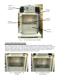
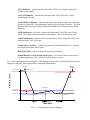
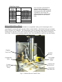
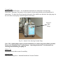
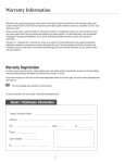
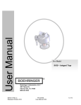
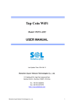
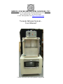
ABBESS INSTRUMENTS AND SYSTEMS, INC.
P.O. Box 498, ASHLAND, MASSACHUSETTS 01721
Phone (508) 881-8811 Fax (508) 881-4884
E-mail [email protected] http://www.abbess.com
Vacuum Infusion System User Manual
Vacuum Infusion System (with optional Curing Oven)
TABLE OF CONTENTS
Safety Considerations – Read before operation
Installation
Vacuum Infusion System Description
Vacuum Chamber, front loading
Infusion Basket and Pneumatic Cylinder
Heated Resin Reservoir
Infusion Process Controller
Infusion Process Control valves, vents, etc.
Vacuum Pump, Fischer LAV-3 (JB DV-85N)
Mobile Cart
Optional Items
System Operation
Maintenance and Cleaning
Calibration
Service and Returns
Shipping – Claims for Damage or Shortage
Warranty
Contacting Abbess Instruments
Appendices
SAFETY CONSIDERATIONS – READ THIS SECTION BEFORE OPERATION
This equipment is designed for use in manufacturing or laboratory environments by trained technicians.
Use of this equipment beyond its stated intended purpose and operating parameters is not recommended
and will be the sole responsibility of the user. This equipment should not be modified or altered.
Abbess Instruments assumes no liability for any misuse of or modification to this product and such
misuse or modification will immediately void all warranties.
This equipment should be used in accordance with the operating instructions contained in this manual.
For alternative uses not covered in this manual, please contact Abbess Instrument’s technical
department for product suitability, safety, and alternative operating instructions.
The following are general safety guidelines recommended when using this product. Please consult
your laboratory safety officer for any additional safety steps that may be necessary for your specific
application or material.
1.
2.
3.
4.
5.
6.
7.
8.
9.
10.
11.
12.
Make sure your operator reads and understands this manual before operating the
equipment.
This equipment is to be operated indoors only.
This equipment is to be operated in a well-lit area.
This equipment is to be operated with an ambient temperature of between 10 degrees C and 40
degrees C.
This equipment is to be operated with an ambient humidity of between 20 and 85 percent.
Thoroughly review your MSDS (Material Safety Data Sheets) for all chemicals to be used with
this equipment.
If the equipment is fitted with an optional internal thermal source (i.e. Thermal Plate) the user
must ensure that temperatures do not exceed the auto ignition point(s) of materials placed in
chamber.
Hand and eye protection are required when using this product. Additional protection may be
required with respect to the materials being used. Please consult your laboratory safety officer.
This product should only be used with adequate ventilation.
A trained electrical technician should conduct repairs of electrical components. Incorrect
replacement parts or assembly may damage the product and create a serious safety hazard for
the user. Factory repair is highly recommended.
The use of samples containing ether based, fuel, munitions, or other extremely flammable or
explosive materials, compounds, or residues should not be used in this equipment.
Use or acidic or base material may damage this product and are not recommended unless the
product was ordered with the optional protective coating in Teflon or made of Stainless steel.
Installation
CHAMBER LOCATION and SETUP
Equipment must be installed in a LOCATION meeting the following criteria:
-
This equipment is to be operated indoors only.
This equipment is to be operated in a well-lit area.
This equipment is to be operated with Adequate ventilation
This equipment is to be operated with an ambient temperature of between 10 degrees C and 40
degrees C.
This equipment is to be operated with an ambient humidity of between 20 and 85 percent.
Equipment must be SETUP with attention paid to the following items of concern.
-
This equipment is to be operated on a stable floor, deck, or platform capable of safely
supporting it and the intended operation.
This equipment maybe secured to the floor, deck or platform as required.
Correct electrical power connections as required.
Adequate ventilation for your people, process, and the vacuum pumps.
All system components assembled, calibrated, tested, and secured as needed.
Vacuum Infusion System Description
Vacuum Infusion System Introduction
The Vacuum Infusion System is used for removing air from porous structures and saturating or infusing
the structure by filling the voids with resin or other liquid materials. The general process flow is a twostep process whereby the structure to be infused is first placed under vacuum to draw off all entrapped
air and then submerged into a reservoir of resin or other liquid infusion material. Once submerged the
chamber is vented back to atmosphere. This reintroduction of air into the chamber acts to uniformly
force the resin into all voids within the structure. Because this process is carried out under vacuum,
there is no air to be trapped inside the item being infused, resulting in complete infusion throughout a
porous structure. The item may then be removed from the chamber for curing or further processing.
The Abbess Instruments Vacuum Infusion System is also equipped with a resin tank heater to facilitate
the flow of viscous resins.
The Vacuum Infusion System consists of the following major components (See Fig.s 1 - 3):
1. Vacuum Chamber, front loading
2. Infusion Basket and Pneumatic Cylinder
3. Heated Resin Reservoir
4. Infusion Process Controller
5. Infusion Process Control valves, vents, etc.
6. Vacuum Pump, Fischer LAV-3 (JB DV-85N)
7. Mobile Cart
8. Optional Convection Oven
1. Vacuum Infusion Chamber
The Infusion Chamber is a cube-shape chamber (Interior Dimensions: 24” high x 20” wide x 20” deep)
constructed from Aluminum with a front-opening Acrylic door. A customer replaceable O-ring seal is
employed to withstand repeated closings. Two draw latches on the sides are used to close door. All
chambers are vacuum tested to 29.92 inches of Hg or better (10-4 torr if required) and should maintain
this for its life dependent on seal condition and customer use.
Installed in the bottom of the Infusion Chamber is the Resin Reservoir. This reservoir is heated by
electrical heating elements attached to its bottom and sides. Electrical power and temperature control
thermocouple wiring is passed through a vacuum feedthru and routed into the Vacuum Cycle
Controller. Into this reservoir is placed the resin or other infusion material.
WARNING
NO INTERNAL PRESSURE MAY BE APPLIED TO THIS CHAMBER
THIS IS A VACUUM CHAMBER
PERSONNEL RESPONSIBLE FOR THIS CHAMBER SHOULD READ THE AMSE CODE
WHICH IS AVAILABLE FROM ASME 345 EAST 47TH STREET, NY, NY 10017
Infusion
Process
Controller
Pressure
Gauge
Infusion
Basket
Vacuum
Chamber
Resin
Reservoir
Fig. 1 – Vacuum Infusion System Chamber
2. Infusion Basket and Pneumatic Cylinder
The “Dunking” operation of the Infusion Basket is fully automated and controlled by the Infusion
Process Controller. Fig.s 2 and 3 show the Infusion Basket in the Up and Down positions. Items to be
infused are placed in the basket. The Pneumatic Cylinder mounted to the top of the chamber enables
automatic raising and lowering of the basket while the chamber is under vacuum. Control of the
cylinder is automatically performed by the Infusion Process Controller.
Fig.2 – Infusion Basket – Up
Position
Fig. 3 – Pneumatic Cylinder –
Down Position
Air Flow
Controls
1
Pneumatic Air
Cylinder
2
Compressed
Air Lines
3
Air Flow
Controls
4
Fig. 4 – Air Cylinder and Flow Controls
The raising and lowering speed of the Infusion Basket can be adjusted using the (4) Air Flow Controls
mounted to the Air Cylinder (see Fog. 4). All Flow Controls are factory adjusted. The reset to factory
settings loosen the lock nuts and hand tighten all (clockwise). Then loosen 1 turn and re-tighten the
lock nuts. The increase speed, loosen more than 1 turn as necessary. Raising/lowering is controlled as
follows:
Flow Controls 1 & 3 control Raise speed.
Flow Controls 2 & 4 control Lower speed.
Note: Factory settings for the Air Cylinder assume a regulated compressed air supply set at 80 psi.
Changing this will affect the raising/lowering speeds.
3. Heated Resin Reservoir
The Heated Resin Reservoir maintains the resin at the optimal working temperature. The temperature
is controlled by the PID Temperature Controller (see Infusion Process Controller and Appendices).
Resin
Reservoir
Fig. 5 – Resin Reservoir
4. Infusion Process Controller
The Infusion process is controlled from the Infusion Process Controller panel mounted on the left side
of the Infusion System cart (Fig. 6).
Temperature
Control
Status
Indicators
Power
On/Off
Manual Basket
Override
(on side)
Start/Stop
Control
Dry/Wet Soak
Dual Timer
Fig. 6 – Vacuum Infusion Process Controller Front Panel
The Infusion Process Controller facilitates control of the Infusion Process via STOP and START
pushbuttons, various system status indicators, PID temperature controller, cycle timer and vacuum
pressure gauge controllers mounted on the front panel.
Front Panel Component Descriptions –
POWER Switch – Turn ON to enable power to the Vacuum Cycle Controller and
vacuum pump.
POWER Indicator – Indicates Power is ON to Vacuum Cycle Controller and pump.
VENT Indicator – Indicates that the state of the VENT valve is Open, venting the
chamber to atmosphere.
VACUUM Indicator – Indicates that the state of the VACUUM valve is Open,
evacuating the chamber.
AT SETPOINT Indicator – Indicates that the pressure in the chamber has reached the
Pressure Set Point (SP1 ON) programmed into the Pressure Gauge Controller. This also
indicates that the system is ready for the Infusion Basket to be lowered into the Resin
Reservoir.
STOP Pushbutton – Resets the system to the initial state (VACUUM valve Closed,
VENT valve Open venting the chamber to atmosphere. The Soak Timers are reset.)
START Pushbutton – Initiates the Vacuum Infusion cycle by closing the VENT valve
and opening the VACUUM valve.
Temperature Controller – Controls the temperature of the Resin Reservoir. Displays
the current temperature and set point.
Dual Soak Timer – Allows control of Dry and Wet Soak times.
Manual Basket Override Switch (on left side) – Use to force basket to raise/lower to
test speed adjustment. Note: Do not use while process is active.
Fig. 7 shows the Infusion Process Diagram. This diagram describes the overall Infusion Process based
on pressure and time. Resin temperature is controlled independently.
Process
Complete
Press Start
(ATM) ~760T
Start Evacuation
Pressure (Torr)
(SP1 OFF) 740T
Raise
Lower Basket
( SP1 ON) 20T
(SP2 OFF) 20T
Hold Pressure Window
( SP2 ON) 10T
Vent Chamber
0T
Dry Soak
WetSoak
Time (Sec)
Fig. 7 – Vacuum Infusion Process Diagram
Setting Target Vacuum Pressure
The two set point relays in the InstruTech CVM-201 Controller are used to determine the points
at which the controller starts the soak timer and closes the vacuum inlet valve. The following
table describes these set points and their initial values:
Set Point
SP1 ON
SP1 OFF
SP2 ON
SP2 OFF
Function
Trigger soak timer to start
Atmosphere, trigger basket to raise
Closes Vacuum Inlet Valve
Opens vacuum Inlet Valve
Initial Value
40 Torr
~740 Torr
20 Torr
40 Torr
Note: See InstruTech Vacuum Gauge Controller User’s Manual for detailed instructions on
operating the controller.
Setting Target Vacuum Temperature
The target temperature of the heated Resin Reservoir is accomplished using the front panel
buttons on the Watlow Series SD PID Temperature Controller mounted in the Vacuum Cycle
Controller. The temperature setpoint is displayed with the smaller green digits. Change the
setpoint by pressing the up/down buttons directly below this display on the face of the
controller. The larger red display indicates the actual temperature of the reservoir.
Soak Timers
Dry Soak – Once the system reaches the working pressure set point (SP1 ON) the Dry Soak
timer starts. This timer allows the air to be removed from the item before being dunked into the
resin. When this timer expires the Infusion Basket will lower into the Resin Reservoir.
Wet Soak – The Wet Soak timer is automatically started once the Dry Soak timer expires and
the Infusion Basket is lowered. This timer determines how long the item will remain
submerged in the Resin Reservoir. When this timer expires the system will turn off the vacuum
pump and vent the chamber back to atmosphere.
Fig. 8 – Soak Timer Operation Chart
GT3W Timer Scales:
Time
Range
Selector
Scale
1S
0-1
10S
10M
1S
10S
0-6
1M
10M
1H
Time Range
0.1 sec - 1 sec
0.3 sec - 10 sec
15 sec - 10 min
0.1 sec - 6 sec
1 sec - 60 sec
6 sec - 6 min
1 min - 60 min
6 min - 6 hrs
Note: The Scale is interlocked and
replaced with the Time Range
Selector. The time range is calibrated
at its maximum time scale, therefore it
is desirable to use the timer at a
setting as close to its maximum time
scale as possible for accurate time
delay.
Process Control Valves, Vents, etc.
The physical process control of each chamber is accomplished with a pair of solenoid gate valves
controlling the vacuum inlet and vent ports of the vacuum chamber. All solenoid valves are activated
by the Vacuum Cycle Controller. The solenoid gate valves are normally-closed and will be closed if no
system power is present. These valves can be accessed by removing one of the panels enclosing the
cart’s body. Under normal operating conditions, these valves and fixtures require no user intervention.
Chamber
Vent Valve
Vacuum
Gauge
Vacuum Inlet
Valve
Air Cylinder
Control
Valve
Vacuum
Inlet from
Pump
Vacuum Line
Vent Valve
Compressed
Air Inlet (80
Fig. 9 – Infusion Process Control Valves
Vacuum Pump
Fischer LAV-3 (JB DV-85N) – See included documentation for maintenance and operating
instructions. Important: The pump’s oil level must be checked periodically per the manufacturer’s
instructions. To check the oil level open the side panel of the mobile cart and check the sight gauge on
the end of the vacuum pump. Refill or replace as necessary.
Oil Level
Sight
Gauge
Fig. 10 – Interior View showing Vacuum Pump
Note: The vacuum pump requires periodic maintenance to ensure long-term reliable operation.
Please read “Platinum Series Vacuum Pumps – Operating Instructions” for information on
checking and maintaining the pump oil.
Mobile Cart
The mobile cart includes casters for mobility.
Optional Items
Convection Curing Oven – Mounted beneath the Vacuum Chamber.
System Operation
Initialize System:
1) Turn the Infusion Process Controller power ON.
2) Verify controller parameter settings as necessary (see Instrutech CVM-201 User’s Manual).
Note: Pressure settings have been pre-set at the factory and do not require user adjustment
under normal operating conditions.
3) Verify Resin Reservoir temperature and set point.
Begin Operation:
4) Load chamber, close door and secure latches.
5) Ensure that Resin is at working temperature. If not, verify Temperature Controller set point.
You may have to wait for the resin to attain working temperature.
6) Press START button.
7) Process cycle begins by starting the pump, closing the Vent valve and opening the Vacuum
Inlet valve.
Active Indicators on the front panel indicate process the status as follows:
POWER = Main power to Vacuum Cycle Controller is ON.
VACUUM = Vacuum Inlet valve is Open.
VENT = Vent valve is Open.
AT SETPOINT indicator will be OFF.
Submerge “Dunk” Infusion Basket (Automatic):
8) When the pressure reaches the preset set point, the green AT SETPOINT indicator will light
and the Dry Soak Timer will begin timing. When the Dry Soak Timer expires the Infusion
Basket will lower into the Resin Reservoir such that items to be infused are completely
submerged and the Wet Soak Timer will start.
End of Process:
9) When the Wet Soak Timer expires, the Vacuum Inlet valve will close and the Vent valve will
open, venting the chamber to atmosphere.
10) When the pressure returns to atmosphere, the Infusion Basket will rise out of the reservoir.
11) Open door and remove item(s).
12) Reload chamber and press START to begin new cycle
or
13) Turn the controller power OFF.
Abort Process:
Pressing STOP at any time will Vent the chamber to atmosphere and return the Vacuum Cycle
Controller to the initial state.
Manual Override for Infusion Basket: Use the toggle switch on the left side of the Infusion Process
Control Panel to manually raise or lower the infusion basket. Note: This action is to be used for
adjusting the speed of the Basket and should not be used while process is active.
Maintenance and Cleaning
Cleaning the Stainless Steel Components - The Stainless Steel components may be cleaned with a
cleaner approved for use with Stainless Steel. Non-abrasive cleaners are recommended to preserve the
surface finish. Non-abrasive scouring pads are recommended. Scrapers and non-metallic scouring
pads may be used on heavily soiled areas. If scrapers are used caution must be used to not damage the
chamber surface. Rinse all areas with water using a sponge or towel. Dry thoroughly.
NOTE: DO NOT RINSE ELECTRICAL EQUIPMENT UNDER RUNNING WATER!!!
Recommended Cleaning Agents
Sheila Shine – Stainless Steel cleaner and polish
Simple Green – All purpose cleaner
Orange Clean – All purpose cleaner
non-abrasive
non-abrasive
non-abrasive
Decontamination – No hazardous materials are used in this equipment. In the event of a hazardous
material spill by the user or outside source, immediately contact your laboratory safety officer or the
manufacturer of the material for instructions on clean up or other decontamination procedures.
Reference your Material Safety Data Sheets (MSDS) for instructions on proper clean-up and handling
procedures.
Calibration
Calibration of all components is subject to user’s internal calibration standards.
Service and Returns
In the event a product purchased from Abbess Instruments needs service or must be returned please
follow the outlined procedures below
Contact Abbess Instruments Technical Support Department
Before returning any product to Abbess Instruments for any reason, please contact Abbess
Instruments at 508-881-8811. Support is available Monday through Friday from 8:30 AM to 5:00
PM EST. Support is available free of charge to customers of Abbess Instruments in good
standing for all products sold by Abbess Instrument.
Pack the Product for Return Shipment
The product should be packaged in its original shipping carton or crate if available. If other
packaging is required, use a suitable shipping container, which will allow a minimum of 2 inches
clearance between the product and the walls of the shipping carton or crate. Peanuts, semi rigid
foam, cardboard, and other items may be used inside for packaging. Care should be taken when
packaging heavy items. Some packaging, such as peanuts, will allow the item to shift in transit
and may result in damage.
Insurance
Most common carriers offer insurance. UPS and Federal Express automatically insure your
product up to $100,000 without charge. It is highly recommended that you insure your product.
Abbess Instruments is not liable for any return shipping damages.
Documentation
When returning items to Abbess Instruments, a packing slip or other document must be included
with the following information: Contact person’s name and phone number, return address, and
statement of the problem.
How Will Your Return be Handled?
Abbess Instruments will evaluate the returned item for damage. If the return is a repair, the
product will be examined for problems and a repair estimate will be make. The contact person
will be contacted, at which time a Purchase Order will be requested. After the PO is issued, the
product will be repaired and return shipped. The repair will be done in an expeditious manner.
The contact person will be notified immediately in the event any shipping damage has occurred.
Shipping – Claims for Damage or Shortage
Abbess Instruments makes a sincere effort to ensure your purchase is properly packed and all items
listed on the packing slip are in fact enclosed with the shipment. In the event that your purchase is
damaged or if any items are missing, please follow the procedures below.
All packaging material must be retained until the issue is resolved.
Thoroughly search all packing material for missing items. Review your packing list for back ordered
items and the manual for a list of items affiliated with your purchase.
Contact Abbess Instruments immediately at 508-881-8811.
Carrier is responsible for breakage in transit! Goods shipped by Abbess Instruments were delivered to
the carrier in good condition. They were packed with great care using standard approved packaging
methods.
If you receive damaged goods, please follow these steps so that we can ensure proper credit to you:
Contact the carrier damage inspection. Hold original carton and merchandise for the inspector.
Please notify Abbess Instruments immediately—(508) 881-8811. DO NOT return damaged goods
to Abbess Instruments without authorization. DO NOT return goods that have not been inspected
by the carrier.
We are willing to assist you in every possible manner, but please be aware that if you fail to follow the
above procedure, the freight carrier or Abbess Instruments may not honor your claim
WARRANTY
ABBESS INSTRUMENTS PRODUCT (THE UNIT) WAS CAREFULLY TESTED AND
INSPECTED BEFORE LEAVING THE FACTORY.
WE WARRANT THIS PRODUCT TO BE FREE FROM DEFECTS IN MATERIAL AND
WORKMANSHIP UNDER NORMAL USE AND SERVICE FOR 12 MONTHS FROM THE
DATE OF RECEIPT.
IN THE EVENT OF DEFECT IN MATERIALS OR WORKMANSHIP, WE WILL EITHER
REPAIR OR REPLACE, AT OUR OPTION, ANY PART WHICH IN OUR JUDGMENT
SHOWS EVIDENCE OF SUCH DEFECT.
THIS WARRANTY DOES NOT COVER WEAR AND DOES NOT APPLY IF, IN OUR
OPINION, THE UNIT HAS BEEN MISUSED, ABUSED, ALTERED, TAMPERED WITH, OR
USED IN LIFE-CYCLE TESTING. ABBESS WILL ONLY BE RESPONSIBLE UP TO THE
COST OF THE UNIT. THIS WARRANTY DOES NOT COVER ANY CONSEQUENTIAL
DAMAGES. AT THE END OF THE WARRANTY PERIOD, ABBESS SHALL BE UNDER
NO FURTHER WARRANTY OBLIGATION EXPRESSED OR IMPLIED.
FOR THIS WARRANTY TO BE VALID A COPY OF THE PACKING LIST MUST BE
SIGNED, DATED AND RETURNED TO ABBESS WITHIN 2 DAYS OF RECEIPT OF THE
UNIT. FOR THIS WARRANTY TO BE VALID CUSTOMERS MUST BE IN GOOD
STANDING.
FOR SERVICE PLEASE REQUEST A RETURN MATERIAL AUTHORIZATION (RMA)
NUMBER FROM ABBESS BY CALLING 1-508-881-8811 AFTER AN RMA HAS BEEN
ASSIGNED, SHIP THE UNIT, IN THE ORIGINAL CRATING, PREPAID,
CONTACTING ABBESS INSTRUMENTS
Shipping Address:
Abbess Instruments and Systems, Inc.
70 Bartzak Dr.
Holliston, MA 01746
USA
Mailing Address:
Abbess Instruments and Systems, Inc.
PO Box 498
Ashland, MA 01721
USA
Phone: 508-881-8811
Fax: 508-881-4884
Email: [email protected]