1
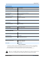
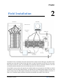
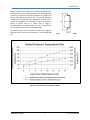
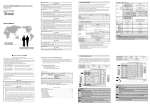
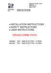
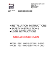
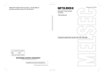
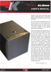
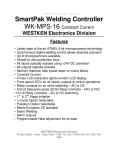
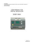
DENT Instruments RōCoil TCA-5™ 5 Amp Transconductance Amplifier Operator’s Guide RōCoil TCA-5 TM Operator’s Guide: RōCoil TCA-5™ © 2013 DENT Instruments, Inc. All rights reserved. This manual may not be reproduced or distributed without written permission from DENT Instruments. Trademarks RōCoil™ and RōCoil TCA‐5™ are trademarks of DENT Instruments, Inc. DENT Instruments | 925 SW Emkay Dr. | Bend,Oregon 97702 USA Phone 541.388.4774 | Fax 541.385.9333 | www.DENTinstruments.com DENT Instruments ii December 13, 2013 Table of Contents INTRODUCTION 4 Product Description ................................................................................................................................ 4 Specifications .......................................................................................................................................... 5 Safety Summary...................................................................................................................................... 6 FIELD INSTALLATION 7 Powering the TCA-5 ................................................................................................................................ 8 Connecting Current Outputs ................................................................................................................ 10 Output Impedance/Burden............................................................................................................ 11 THEORY OF OPERATION 12 Input Signal ........................................................................................................................................... 11 Range Selection .................................................................................................................................... 12 Integration ............................................................................................................................................ 13 Frequency Selection ............................................................................................................................. 13 Performance ......................................................................................................................................... 13 FREQUENTLY ASKED QUESTIONS December 13, 2013 iii 15 DENT Instruments Chapter 1 Introduction Product Description The RōCoil TCA-5™ is a three channel integrating transconductance amplifier that translates the electrical output signal from a flexible RōCoil™ current sensor to a 5-amp AC current, emulating a traditional 5A secondary current sensing transformer. This combination enables the flexibility and ease of installation of the RōCoil to be extended to applications having power meters or panels that cannot process a RōCoil signal directly. The RōCoil TCA-5 is a DIN rail- or panel-mounted device requiring an external 48-volt power supply (available as an option). The RōCoil TCA-5 has four selectable current ranges: 500, 1k, 2.5k, and 5k amps and is accurate for both 50 and 60 Hz systems. The RōCoil TCA-5 has been factory calibrated for DENT RōCoil current sensors with an output of 131.0 mV per thousand amps at 60 Hz. NOTE: The RōCoil TCA-5 has been tested for electromagnetic compatibility (EMC) as an assembly which includes a discrete filter between the 48 volt DC power suppl and the TCA-5. Removal of this filter may result in spurious results or saturation of the high gain internal amplifier. Figure 1-1: Anatomy of the 5-Amp RōCoil TCA DENT Instruments 4 December 13, 2013 RōCoil TCA-5 TM KEY SPECIFICATIONS Input Measurement Voltage 0 – 655 mV (RMS) RōCoil Current Range 0.5 – 5000 amps (80 dB Signal Range) Output Current 0 – 5.00 amps (RMS)* RōCoil Sensing Ranges 500, 1K, 2.5K, 5K Amps (User-selectable) Maximum Burden 1.25 VA per channel Maximum Output Impedance 50 m-ohms Measurement Channels 3 (3-phase or single phase) Frequency 50/60 Hz Select Accuracy 1%** Channel Cross Talk < 60 dB Maximum Operating Temp 60 deg C (140 deg F) POWER REQUIREMENTS TCA Supply Voltage 48 VDC +/- 10%, 30 Watts TCA Supply Current 0.6 amps DC @ 48 VDC DIMENSIONS/MOUNTING Width Base Unit/Assembled 15.7 cm (6.2”)/25.0 cm (9.8”) Height Base Unit/Assembled 9.0 cm (3.5”)/12.6 cm (5.0”) Input Wire Connection 18 – 28 AWG Output Wire Connection 12 – 18 AWG (length dependent) ACCESSORIES AC/DC Power Supply, 50 watts Low Voltage: 120/240 VAC High Voltage: 200/500 VAC Mounting Rail TS35/7 DIN Rail Table 1-1: Specifications * The RōCoil TCA-5 is limited to 19 amps of peak instantaneous current. The 19 amp limit is reached at 6.7 amps (RMS) when measuring 3 phase loads but is reduced to 4.5 amps (RMS) when measuring three currents on the same phase. NOTE: Operating with an output channel over 5 amps RMS can cause the RōCoil TCA-5 to overheat and become damaged. ** All accuracies specified at 20° C (+/- 2° C) with RōCoil centered on conductor. Typical accuracy with RōCoil CTs < 1%. TIP: Use a “true RMS” DVM to measure the voltage across the output terminals of the RōCoil TCA-5. A voltage above 250 mV RMS indicates that the signal may be clipped. December 13, 2013 5 DENT Instruments RōCoil TCA-5 TM Safety Summary This general safety information is to be used by both operator and servicing personnel. DENT Instruments, Inc. assumes no liability for user’s failure to comply with these safety guidelines. Conforms to UL STD 61010-1 Conforms to CAN/CSA STD C22.2 No. 61010 CAUTION: Service panel voltages may contain life-threatening voltages. QUALIFIED PERSONNEL MUST install CTs or power leads using methods consistent with NEC and local codes. WARNING! Use of this device in a manner for which it is not intended may impair its means of protection. When connecting the RōCoil TCA-5™ to an AC load, follow these steps to prevent a shock hazard. 1. If possible, de-energize the circuit to be monitored. 2. Connect the CTs to the phases being monitored. 3. Use proper safety equipment (gloves, mask, and protective clothing) as required. Risk of electrical shock. Life-threatening voltages may be present. All work should be performed by a qualified electrician using proper safety equipment. Dispose of properly. FCC COMPLIANCE This device has been tested and found to comply with the limits for a Class A digital device, pursuant to part 15 of the FCC Rules. These limits are designed to provide reasonable protection against harmful interference when the equipment is operated in a commercial environment. This equipment generates, uses, and can radiate radio frequency energy and, if not installed and used in accordance with the instruction manual, may cause harmful interference to radio communications. Operation of this equipment in a residential area is likely to cause harmful interference in which case the user will be required to correct the interference at user’s own expense. Operation is subject to the following two conditions: (1) This device may not cause harmful interference and (2) this device must accept any interference received, including interference that may cause undesired operation. DENT Instruments 6 December 13, 2013 Chapter Field Installation 2 Figure 2-1: Recommended Installation The RōCoil TCA-5 is intended to be wall mounted with the output terminal facing up. The RōCoil TCA-5 generates up to 20 watts of internal heat and relies on natural convection to cool itself. The unit must have access to fresh air and is not intended to be mounted inside an electrical enclosure. The area immediately below and above the unit should be kept clear of air flow obstructions. Three RōCoil current sensors will typically be installed inside the service panel at the feeder or around the branch circuit of interest. Best practice is to separate the AC voltage (used to power the TCA-5 and power meter) from the RōCoil signal conductors by running them in separate conduits (as shown in Figure 2-1). The RōCoil signal shield wires should be terminated at the RōCoil TCA-5 end only. December 13, 2013 7 DENT Instruments RōCoil TCA-5 TM Powering the TCA-5 The TCA-5 operates from 48 volts DC +/- 10% and has a full power consumption of 30 watts. The DC connections are made in the lower right hand corner of the unit (inset image). The DC connection is polarity sensitive and will only power up if applied with the correct polarity. Backwards polarity will not damage the unit but it will not turn on. DENT Instruments offers two DIN rail-mounted AC/DC power supplies for line powering: High voltage (200 – 500 VAC) and Low voltage (100 – 240 VAC). The High Voltage model is suggested for all three phase power systems and the Low Voltage model is suggested for single phase residential customers. In both cases the AC/DC power supply input is connected between two phases of incoming voltage. DENT Instruments recommends powering the AC/DC power supply through a dedicated breaker to avoid the use of “tap rules” whenever space allows (as shown in Figure 2-1). If the TCA-5 is powered from an auxiliary control transformer rather than directly from line power ensure that the transformer has 30 VA of available capacity. DENT Instruments 8 Figure 2-2: DC Connections December 13, 2013 RōCoil TCA-5 TM Where enclosures are required to protect the RōCoil TCA-5 from exposure to the local environment the following graph (courtesy of Hoffman Enclosures) provides an indication of the smallest allowable enclosure size. The internal enclosure temperature cannot be allowed to exceed 60° C (140° F) if full current is demanded from the RōCoil TCA-5. An enclosure having a surface area of 3 square feet or larger is recommended for a typical design case: 20° C temperature rise, 20-watt internal load, 6.7-watt/square foot. The RōCoil TCA-5 can be mounted as a panel unit using the slide-out tabs on the back or mounted on a 35 mm-width DIN rail. Figure 2-3: Top hat EN 50022 Rail Figure 2-4: Sealed Enclosure Temperature Graph December 13, 2013 9 DENT Instruments RōCoil TCA-5 TM Connecting Current Outputs 1) Open the CT by squeezing the connector latch and pulling it apart. 2) Connect the CT around the conductor to be measured. Make sure no other conductors are within the loop formed by the CT. Orient the CT so that the arrow on the CT connector points in the direction of conventional current flow (toward the load). Figure 2-5: RōCoil Connectors 3) Push the connector back together with the conductor within the loop of the CT. 4) Mark and route the RōCoil signal wires to the RōCoil TCA-5. Figure 2-6: Signal Wire 5) Identify and terminate the signal wires for connection to the RōCoil TCA-5. CT + LEAD CT - LEAD SHIELD White Brown Bare Table 2-1: Connection Color Code The output connector polarity is marked on top of the enclosure. Output connections should be tightened to 0.8 Nm (7 in-lbs) to ensure a low termination impedance. Avoid routing the output wires in close proximity with the signal input wires to avoid introducing feedback. Both the input and output circuitry are tolerant of plugging and unplugging under load without damaging the TCA. DENT Instruments 10 December 13, 2013 RōCoil TCA-5 TM OUTPUT IMPEDANCE/BURDEN The RōCoil TCA-5 is a bipolar push/pull current source that operates internally from a +/- 1.0 volt DC power supply. The design senses the output current using a precision resistor and drives a pair of MOSFETS through a feedback loop to control the current. Linearity and precision is maintained as long as the requested current can be delivered within the voltage compliance of the DC supply. The fraction of voltage drop allowed by the output circuity (i.e., the voltage loss due to current flowing through the sum of the wire resistance and meter burden) is 250 mV. This condition is satisfied at 5.0 amps RMS with a crest factor of 1.414 for an output impedance of 50 m-ohms. Another way to express this limit is a burden of 1.25 VA. The 50 m-ohm output impedance plays a critical role in the selection of output wire size and the allowable distance between the power meter and the RōCoil TCA-5. The table below has been generated assuming that the meter burden is 5 m-ohms, leaving 45 m-ohms for the wire. Note that the meter distance is half the wire length. WIRE AWG M0HMS PER FOOT MAX METER DISTANCE (FT) 12 1.588 14.35 14 2.525 8.9 16 4.016 5.6 17 5.064 4.4 18 6.385 3.5 20 10.15 2.4 Table 2-2: Allowable Distance TIP: Twisting the output cables together to reduce the effects of electromagnetic interference shortens the physical length of the cable by approximately 20%. Table 2-2 sets the practical maximum length between the meter and the RōCoil TCA-5. Extremely short cable connections with large wire should also be avoided. Because the amplifier operates from a fixed DC supply voltage the power delivered by the amplifier is the same for a given current regardless of the output impedance. The output impedance impacts where the heat is generated. If the RōCoil TCA-5 is delivering 5 amps and the output impedance is near zero, then the full 1.875 watt burden is placed on the internal MOSFETS. The design can tolerate this condition but the temperature of the amplifier will increase considerably, reducing the accuracy of the system. TIP: Use a “true RMS” DVM to measure the voltage across the output terminals of the RōCoil TCA-5. A voltage above 250 mV RMS indicates that the signal may be clipped. December 13, 2013 11 DENT Instruments Chapter 3 Theory of Operation Input Signal DENT RōCoil current sensors produce a signal voltage in accordance with 𝑉= −ANµo dl dt L Where I is the current flowing in the measurement conductor and A,N, μo, and L are determined by the physical construction of the RōCoil. DENT RōCoils are manufactured to produce 2.183 131.0 mV/kA @ 60 Hz and 109.2 mV/kA @ 50 Hz. uV∗Hz Amp which is more commonly expressed as The RōCoil TCA-5 is factory calibrated for use with DENT RōCoils. The use of other Rogowski brands will introduce a scaling error. The RōCoil TCA-5 is extremely sensitive and accurately translates conductor currents between 500 mA and 5000 amps into meter currents between 500 uA and 5.0 amps. The operation of the RōCoil TCA-5 is best expressed using vector notation and is illustrated as a vector diagram in Figure 3-1, next page. The voltage generated by the RōCoil sensor leads the current flowing in the measurement conductor by almost 90 degrees (angle exaggerated for clarity), labeled (1). The positive X axis (0 degrees) is the current vector of the conductor being measured. December 13, 2013 12 DENT Instruments RōCoil TCA-5 TM Figure 3-1: RōCoil TCA™ Vector Diagram Range Selection The RōCoil TCA-5 range selection slider switch selects the primary gain of the amplifier. Internal feedback with gains of 1, 2, 5 and 10 are selected using laser trimmed precision resistors within an inverting precision operational amp circuit (shown as vectors 2 and 3 in Figure 3-1). The Current Range Selector is normally set to the nearest value over the size of the breaker feeding the load being measured. For example, the 1000 amp setting would be used with an 800 amp service breaker. If the size of the load is known to be much smaller than the service capacity, better accuracy can be obtained by selecting the range closest to the actual usage. If the actual current is higher than the selected range the RōCoil TCA-5 waveform will be clipped and will not give an accurate reading. The effect of clipping the waveform is illustrated in Figure 3-2. December 13, 2013 13 DENT Instruments RōCoil TCA-5 TM Severely clipped waveforms resemble a square wave. Ensure that the selected current range of the meter is above the current flowing in the measurement circuit to avoid this condition. NOTE: The RōCoil TCA-5 will not be damaged if the output is over-ranged and is clipping. Vp +V c 0 -Vc Unclipped sinewave Clipped sinewave Vp<Vc Vp>Vc Figure 3-2: RōCoil Clipped Waveform TIP: Use a “true RMS” DVM to measure the voltage across the output terminals of the RōCoil TCA-5. A voltage above 250 mV RMS indicates that the signal may be clipped. Integration The RōCoil TCA-5 employs an internal precision analog integrator to compensate for the phase angle produced by the RōCoil current sensor (vector 4). For this reason the TCA cannot be used with a 333mV split core current transducer unless the phase information is not needed. Frequency Selection The RōCoil TCA-5 has been specifically designed and calibrated to work with 50 and 60 Hz circuits. The 50/60 Hz slider selects one of two small angle correction vectors and inverting vectors (5 and 6) bringing the amplifier phase within 0.1 degree of the reference conductor phase. If the incorrect frequency is selected a phase error of 0.6 degrees will result. The sensitivity of the phase to frequency is approximately .06 degrees per Hz. The RōCoil TCA can be used on portable generators where frequency is not well regulated. Consult DENT Instruments for use of the RōCoil TCA-5 on 400 Hz circuits. Performance The RōCoil TCA-5 can be supplied with RōCoil flexible current transformers (purchased separately). The combined errors of the TCA used in conjunction with supplied CTs is typically better than 1%. CURRENT RANGE SETTING MIN CURRENT @ 1% ERROR MAX CURRENT 500 A 5A 500 A 1000 A 10 A 1000 A 2500 A 25 A 2500 A 5000 A 50 A 5000 A Table 3-1: Min/Max Current Range DENT Instruments 14 December 13, 2013 Chapter 4 FAQs Frequently Asked Questions How can I tell if the amplifier is clipping? The voltage across the output terminals is above 250mV RMS. Correct this by using a larger wire gauge or moving the TCA-5 closer to the meter. Does output clipping damage the unit? Clipping the output signal does not harm the TCA-5 as long as the output current remains less than 5 amps, as in the case when the output impedance is greater than 50m-ohms or the output wires are disconnected. Why does the TCA-5 run so hot? Each channel dissipates approximately 5 watts of heat at full power. Why is the TCA-5 limited to 4.5 Amps RMS on 3 single-phase loads? The TCA-5 has a peak internal current of 19 amps. Is there any configuration that can cause the TCA-5 to fail? The TCA-5 will attempt to deliver more than 5 amps if the current being measured is larger than the selected range. For example: placing the RōCoil current sensor around a conductor with 900 amps flowing through it. The TCA-5 will deliver 9 amps of current into the output even though the 500 amp range is selected on the front panel. If the output burden is low enough, the TCA will deliver the requested current and burn out the channel if this condition persists. Note that this scenario is limited to single phase measurements. A balanced three phase system will share the current between channels preventing any one channel from overheating. Is there a 24-volt version? Not at this time. Is there a single phase version? The TCA-5 can be used on single-phase circuits, however there is currently no "1 channel model." DENT Instruments 15 December 13, 2013 RōCoil TCA-5 TM Can the TCA-5 be used with 333mV current sensors? The TCA-5 includes a 90 degree phase shifter. It can only be used with 333mV sensors to report current, NOT POWER. I had the 50Hz selector on by mistake. Is my collected data any good? Yes, the phase angle will be reported 0.6 degrees higher than actual, which is also about 0.6% low for a PF of 0.866. DENT Instruments 16 November 27, 2013