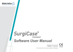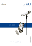
1
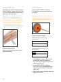
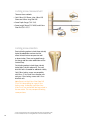
Surgical Technique Including TRIGEN™ META-NAIL™ Tibial Nail System Surgical Technique Table of contents Indications................................................................ 2 Implant specifications............................................. 4 Surgical technique Patient positioning..................................................... 5 Incision and entry point............................................. 10 Entry portal acquisition ............................................. 11 Entry portal................................................................. 12 Alternative technique: Entry portal............................ 12 Fracture reduction...................................................... 14 Reducer removal........................................................ 14 Implant measurement................................................ 15 Unreamed technique................................................. 16 Reamed technique..................................................... 17 Nail assembly............................................................. 19 Nail insertion.............................................................. 25 Check nail depth........................................................ 26 Locking screw measurement..................................... 32 Locking screw insertion............................................. 32 Proximal locking: Static.............................................. 33 Proximal locking: Dynamic......................................... 33 Proximal locking: Compression ................................ 34 Blocking screw technique Incision and entry point............................................. 36 Entry portal acquisition............................................... 36 AP blocking screw insertion...................................... 37 ML blocking screw insertion...................................... 38 Blocking screw insertion with reducer....................... 39 Stability blocking screw insertion.............................. 40 Nail cap insertion....................................................... 41 Nail extraction: Optional Standard technique................................................... 43 Percutaneous technique............................................ 43 Guide rod jamming technique................................... 44 Catalog information................................................. 45 Nota Bene The technique description herein is made available to the healthcare professional to illustrate the authors’ suggested treatment for the uncomplicated procedure. In the final analysis, the preferred treatment is that which addresses the needs of the patient. 1 Indications The TRIGEN™ META-NAIL™ Tibial Nail is indicated for fractures of the proximal and distal third of the tibia, including the shaft, stable and unstable fractures, nonunions, malunions, and for the prophylactic nailing of impending pathological fractures. 2 TRIGEN™ SURESHOT™ indications Legend Important warnings appear in orange Tips, tricks and important information appear in blue Indications, contraindications, intended use and training The Smith & Nephew TRIGEN™ SURESHOT™ Distal Targeting System is intended to be an intraoperative image-guided localization system. It is a computer-assisted orthopaedic surgery tool to aid the surgeon with drill positioning for screws during intramedullary nail implantation. It provides information to the surgeon that is used to place surgical instruments during surgery utilizing intraoperatively obtained electromagnetic tracking data. The Smith & Nephew TRIGEN SURESHOT Targeting System is indicated for long bone fractures treated with intramedullary nails in which the use of stereotactic surgery may be appropriate. An example of a surgical procedure includes but is not limited to locating and drilling the distal holes in an intramedullary nail. Contraindications The screw targeting software application for this system is contraindicated for all IM nails other than Smith & Nephew TriGEN META-NAIL™, TAN™, FAN, Humeral, Pediatric and Adolescent nails. Do not operate the TRIGEN SURESHOT Targeter within 200mm of an installed pacemaker. The magnetic field produced by the Targeter may interfere with the operation of the pacemaker. Intended use The TRIGEN SURESHOT Distal Targeting System is only designed for use with the indicated implants and instruments. Implants and instruments must be used in accordance with the instructions, as described in this manual and/or in the non-navigated surgical procedure. Training Only trained operators are allowed to use the TRIGEN SURESHOT Distal Targeting System. The various operating instructions must be fully read and understood as part of the training. If any part of the instructions is unclear, please contact your local Smith & Nephew representative. Plausibility check As with all technical equipment, malfunctions may occur due to improper use or, more rarely, technical failure. To reduce the risks involved with such technical malfunction the operation can be completed using manually controlled instruments, providing the malfunction is detected without delay. It is, therefore, important to check the plausibility of the steps, as indicated by the system, and to carry out verification of the software targeting, particularly when using the system for the first time. Should there be any doubt regarding correct functioning, the targeting should be verified or a switch made to a traditional X-Ray technique. Refer to the SURESHOT User Manual (7118-1540) for details about the SURESHOT Distal Targeting System. 3 TRIGEN™ META-NAIL™ Tibial Nail specifications 10º Specifications 27mm Driving end of nail (all knee and distal tibial) TriGen META-NAIL Tibia (8.5mm) TRIGEN META-NAIL Tibia Material TI6AL4V TI6AL4V Diameter 8.5mm 10, 11.5 & 13mm Lengths 16-50cm* 16-50cm* Nail Color Grey Gold Cross Section Round Round Proximal Diameter (driving end) 12mm Distal Diameter (non-driving end) 8.5mm 10, 11.5 & 13mm Smallest Thru Diameter 4.8mm 5.0mm Wall Thickness 1.9mm Guide Bolt Thread 5/16-24 UNF 5/16-24 UNF Screw Diameter 4.5mm 5.0mm Screw Color Grey Gold Major Diameter 4.5mm 5.0mm Minor Diameter (core) 4.0mm 4.3mm Screw Lengths 25-65mm 25-110mm Hex Size 4.7mm 4.7mm RT Femoral & Recon PERI-LOC™ Locking Screw RT Femoral & Recon 7.0mm Cannulated Screw PERI-LOC™ 4.7mm Hexdriver, PROFIX™ 4.7mm Hexdriver No No 12mm (10, 11.5 dia.) 13mm (13 dia.) 2.3mm (10) 3.0mm (11.5) 2.3mm (13) Top view of nail Alternative Hexdrivers Alternative Modes 7.0mm Cannulated Screw Proximal Locking (Driving End) Static Lock Locations/Orientations Static Locking Hole Dimensions Compression/Dynamic 60mm Threaded 4.7mm major dia. Threaded 5.3mm major dia. 10mm 10mm 4.7mm/7mm 5.3mm/7mm 10° 10° 27mm 27mm 25mm/ML 25mm/ML 15mm/AP 15mm/AP 5mm/ML (Threaded) 5mm/ML (Threaded) 4.7mm** 5.3mm** Degree of Distal Bend 2° 2° Distal Bend Location 60mm 60mm Slot Location Compression/Dynamic 2º ML view Non-driving end of nail (AP view) 17mm/45° Screw Locked w/META-Nail Cap 23mm/45° Threaded w/bushing 30mm/25° Threaded 40mm/25° Threaded Threaded 4.3mm minor dia. Threaded 4.5mm minor dia. Slot Diameter/Length Degree of Proximal Bend (Herzog) Proximal Bend Location Distal Locking Note These views are not to scale and should be used as a pictorial representation only. (Non-Driving End) Static Lock Locations/ Orientations Static Locking Hole Dimensions * Set does not include all sizes; Outlier sizes may be special order only. ** Most distal hole threaded. 4 Surgical technique Patient positioning Position the patient supine on a radiolucent table with the unaffected limb extended away from the affected limb. Alternatively, a fracture table may be used with a pin inserted through the calcaneus to place the leg in traction. Flex the affected limb 80-90° and check for length and rotation by comparison to the unaffected limb. Use a bolster or radiolucent triangle to maintain limb position. Rotate the C-Arm to ensure optimal AP and lateral visualization of the entire tibia. A distraction device may also be applied to obtain and/or maintain traction. Caution Do not use a metal bump because it will adversely affect the accuracy of the TRIGEN™ SURESHOT™ system. 5 Warnings and cautions for TRIGEN™ SURESHOT™ Refer to the SURESHOT User Manual (7118-1540) for all warnings, cautions, maintenance, cleaning and sterilization instructions. Devices for system set up TRIGEN™ SURESHOT™ Targeter Cat. No. 7169-2801 Trauma Interface Cat. No. 7169-2802 Power Cord Cat. No. 6680-0193 Note The Targeter will be operated within the sterile field and may have contact with the skin of the patient. The drill sleeve inserts will be used in the incision and have direct bone contact. Note Verify that the Targeter housing is not damaged (holes, tears, cracks). If the housing or the connector is damaged, the Targeter is no longer safe to use. Note If the Targeter is not recognized after connection to the system, the Targeter is defective and must be exchanged. (See also instrument connection). Note Broken or damaged instruments must be exchanged immediately and sent back to Smith & Nephew, Inc. Note This device is provided non-sterile and must be cleaned and sterilized per Cleaning and Sterilization (Smith & Nephew document 7138-1339) prior to use. WARNING: The maximum temperature of the Targeter body can reach 47° Celsius at ambient room temperatures above 30° C. The Targeter body should not remain in constant contact with a patient’s exposed skin for more than one minute. 6 Surgical procedure – OR preparation Trauma Interface setup After the sterile areas have been established, place the Trauma Interface (7169-2802) in the desired non-sterile location and turn on the power switch. CAUTION: No other electrical devices should be placed near the Trauma Interface. See the “Guidance and Manufacturer’s Declaration – Separation Distances” table at the end of this document. Note If the Trauma Interface does not power on, make sure the switch is in the “on” position. Note The means for mains disconnection of power to the Trauma Interface is the appliance inlet located below the power switch. The Trauma Interface should not be positioned such that it is difficult to reach this location. TRIGEN™ SURESHOT™ Targeter connection When the display prompts for tool connections, connect the TRIGEN SURESHOT Targeter (7169-2801) to the Targeter port on the Trauma Interface. 7 Surgical procedure – OR preparation The SURESHOT™ Targeter will change color to orange upon successful connection to the Trauma Interface. CAUTION: The Targeter body may have contact with the patient and must remain in the sterile field at all times. Only the cable and connector may be removed from the sterile field. CAUTION: Connect the Targeter at least 10 minutes prior to targeting in order to ensure proper accuracy. Note When oriented as shown, the connector should assemble easily. Do not force the connector into the port. Note If the Targeter is properly connected to the system and the application remains in this screen for more than 30 seconds, the Targeter may have been damaged during cleaning/sterilization. In this case another Targeter has to be used. Note It is possible at any time to disconnect and reconnect tools when the application is running. The display will show a screen reporting the missing instrument. 8 Instruments for opening the proximal tibia 3.2mm Tip Threaded Guide Wire Cat. No. 7163-1690 Mini Connector Cat. No. 7163-1186 12.5mm Entry Reamer Cat. No. 7163-1116 Honeycomb Cat. No. 7167-4075 Entry Portal Tube Cat. No. 7167-4060 Entry Portal Handle Cat. No. 7167-4092 T-handle Cat. No. 7167-4076 3.2mm T-handle Trocar Cat. No. 7167-4074 Cannulated Awl Cat. No. 7167-4000 9 Incision and entry point Assemble the Honeycomb (7167-4075), Entry Portal Handle (7167-4092) and Entry Portal Tube (7167-4060). The pieces will lock in place securely at either 0° or 180°. A 2cm incision is made in line with the intramedullary canal. This may be patellar splitting, medial or lateral parapatellar in its orientation. The entry point is located just medial to the lateral tibial eminence in the AP view, and in line with the anterior cortex and intramedullary canal in the lateral view. 10 Entry portal acquisition Attach a 3.2mm Tip Threaded Guide Wire (7163-1690) to the drill via the Mini Connector (7163-1186) and insert into the proximal tibia to a depth of 4-6cm. The Entry Portal instrumentation serves as a soft-tissue protector. In the instance of suboptimal Guide Wire insertion, rotate the Honeycomb within the Entry Tube to the desired location and insert another 3.2mm Tip Threaded Guide Wire. Avoid over-insertion of the Guide Wire as this can establish a false trajectory and lead to fracture malalignment. 11 Entry portal After definitive Guide Wire placement, remove the Honeycomb from the Entry Tube along with any additionally inserted Guide Wires and attach the 12.5mm Entry Reamer (7163-1116) to power. Advance over the Guide Wire through the Entry Tube to a depth of 4-6cm. Maintain alignment so as to avoid penetration of the posterior cortex. Check position via radiographic imaging and then remove the 12.5mm Entry Reamer and 3.2mm Tip Threaded Guide Wire. Alternative technique: Entry portal Attach the T-handle (7167-4076) to the Cannulated Awl (7167-4000) and insert into the proximal tibia to a depth of 4-6cm. Introduce the 3.2mm T-handle Trocar (7167-4074) into the back of the assembly prior to insertion in order to prevent awl slippage and accumulation of cortical bone within the cannulation. Cannulated Awl with T-handle 12 3.2mm T-handle Trocar Instruments for fracture reduction and reaming Entry Portal Tube Cat. No. 7167-4060 Entry Portal Handle Cat. No. 7167-4092 Ruler Cat. No. 7167-4079 Gripper Cat. No. 7167-4080 Obturator Cat. No. 7167-4078 Flexible Reamer Shaft Cat. No. 7111-8200 T-handle Cat. No. 7167-4076 Reducer Cat. No. 7167-4077 Reamer Heads Cat. No. 7111-8231–8246 3.0mm x 1000mm Ball Tip Guide Rod Cat. No. 7163-1626 13 Fracture reduction Insert the back end of the 3.0mm Ball Tip Guide Rod (7163-1626) into the front of the Gripper (7167-4080) and gently close the trigger grip. Connect the Reducer and Reducer Connector (7167-4077) so that the words “Slot Orientation” are in line with the opening at the tip. Complete the assembly by connecting it to the T-handle (7167-4076). Note If blocking screws are desired at this point in the procedure, refer to the blocking screw technique section. Advance the Reducer into the intramedullary canal and use the curved tip to direct the 3.0mm Ball Tip Guide Rod past the fracture into the region of the distal epiphyseal scar. The guide rod should be center-center in the AP and lateral views. Reducer removal Once the guide rod is at the desired depth, detach the Gripper and remove the Reducer from the tibial canal. Slide the Obturator (7167-4078) into the back of the T-handle during extraction in order to maintain guide rod position within the canal. 14 Implant measurement After Reducer removal, reconfirm guide rod placement within the distal tibia and slide the Ruler (7167-4079) over the guide rod to the desired depth. The metal tip of the Ruler denotes the driving end of the META-NAIL™ Tibial Nail. Confirm guide rod position in the window at the opposite end of the Ruler as shown in order to ensure accurate implant measurement. Push down on the top of Ruler until contact is made with the 3.0mm Ball Tip Guide Rod. Implant length is read from the exposed calibrations at the end of the Ruler. Note Confirm fracture reduction so as not to underestimate correct implant length. Reference the fibula for accurate fracture distraction or compression. Note Confirm that the Ruler opens easily. Adjust the thumb-wheel connection at the end to allow for free movement. 15 Unreamed technique Radiographic templating is used to determine nail size. The appropriate diameter implant will provide translational fill within the isthmus of the intramedullary canal. Generally, selection of a nail approximately 1-1.5mm less than the narrowest canal measurement on the lateral radiograph assists in avoiding implant incarceration during insertion. TRIGEN™ META-NAIL™ Tibial Nail Radiographic Template Cat. No. 7118-0810 16 Reamed technique Radiographic templating and intraoperative measurement will determine nail size. Beginning with the 9.0mm Front Cutting Reamer Head (7111-8231) and Flexible Reamer Shaft (7111-8200), ream the intramedullary canal sequentially in half millimeter increments to a size 1-1.5mm larger than the selected nail size. Ensure guide rod placement during reaming by inserting the Obturator into the back of the Reamer unit during retraction. Continue to confirm Guide Rod placement in the distal tibia throughout reaming. Periodically move the reamer back and forth in the canal to clear debris from the cutting flutes. 17 Instruments for nail assembly and insertion Guide Bolt Wrench Cat. No. 7163-1140 META-NAIL™ Anterior Drop Cat. No. 7165-4501 9.0mm Drill Sleeve Cat. No. 7163-1152 META-NAIL Drill Guide Cat. No. 7165-4502 META-NAIL Extension Drill Guide Cat. No. 7165-4503 Extension Guide Bolt Cat. No. 7165-4505 Note TRIGEN™ SURESHOT™ cannot be used with this guide. Cannulated Impactor-Short Cat. No. 7165-4554 4.0mm Drill Sleeve Cat. No. 7167-4083 4.0mm Long Pilot Drill* Cat. No. 7163-1110 Guide Bolt Long Cat. No. 7165-4506 Cannulated Impactor-Medium Cat. No. 7167-5081 Slotted Hammer Cat. No. 7167-4082 T-handle Cat. No. 7167-4076 META Set Stop Cat. No. 7169-2806 META-NAIL Standard Drill Guide Probe Cat. No. 7169-2814 * 4.0mm Long Pilot Drill (7163-1110) is interchangeable with 4.0mm AO Long Drill (7163-1121) 18 Nail assembly Attach the META-NAIL™ Drill Guide (7165-4502) to the nail with the Guide Bolt Long (7165-4506) and tighten with the Guide Bolt Wrench (7163-1140) and T-handle. The nail is correctly aligned when: 1 The line on the insertion barrel matches the line of the nail. 2The “A” on the nail matches the “A” on the insertion barrel. 3The apex of the nail’s proximal Herzog Bend faces posterior and the drill guide is oriented anterior. The bevel on the front of the nail marks the connection to the drill guide and can be seen in the lateral view as a means for determining proximal insertion depth. Note It is recommended to use the standard drill guide and Guide Bolt Long for compression or dynamic locking as the longer insertion barrel facilitates countersinking of the nail. Note The assembly and insertion of the grey 8.5mm diameter META-NAIL Tibial Nail follows the same technique as the 10mm, 11.5mm and 13mm diameter nails. Attach the Anterior Drop (7165-4501) to the drill guide and verify targeting accuracy by inserting a gold 9.0mm Drill Sleeve (7163-1152) and silver 4.0mm Drill Sleeve (7167-4083) into the Drop and passing a 4.0mm Long Pilot Drill (7163-1110)* through the assembly. An incorrectly attached nail will not target. Note Refer to SURESHOT™ User Manual for the field accuracy check instructions. * 4.0mm Long Pilot Drill (7163-1110) is interchangeable with 4.0mm AO Long Drill (7163-1121) 19 Surgical procedure – after IM Nail Assembly to the Drill Guide Probe selection and assembly Probe connection Assemble the appropriate probe and set the stop for the the TRIGEN™ IM Nail and Drill Guide that will be used. Connect the probe to either of the probe sensor ports on the Trauma Interface. CAUTION: Proper orientation of the probe to the set stop as shown is required. Failure to do so may result in inaccurate targeting. TRIGEN SURESHOT™ META-NAIL™ Standard Drill Guide Probe (7169-2814) For META-NAIL, notches should face anteriorly Confirm that the tool connection has been verified. Red probe Use only with META-NAIL Standard Drill Guide (7169-2814) Note When oriented as shown, the connector should assemble easily. Do not force the connector into the port. Simply try rotating the connector until the keys are oriented in the 12 o’clock position. Set the probe to the length of the TRIGEN IM Nail. Note If the probe is properly connected to the system and the application reports “Probe not found” for more than 10 seconds, the probe may be damaged or defective. In this case, the probe has to be exchanged. Note It is possible at any time to disconnect and reconnect tools when the application is running. The display will show a screen reporting the missing instrument. 20 Surgical procedure – after IM Nail Assembly to the Drill Guide Drill sleeve selection Select the length of the drill sleeve (7169-2804, 7169-2805, or 7169-1165 and 7169-1166) that will be used. A different sleeve can be selected at any time during the procedure by choosing the drill sleeve option from the drop down menu OR by pressing the drill sleeve tab located in the lower right corner of the navigation screen. Implant selection screen Select the TRIGEN™ IM Nail and size that will be used. META-NAIL™ Note A different TRIGEN IM Nail and/or size can be selected at any time during the procedure by choosing the Implant option from the drop down menu OR by pressing the implant tab located in the lower left corner of the navigation screen. 21 Surgical procedure – after IM Nail Assembly to the Drill Guide Drill sleeve attachment Tightly secure the selected drill sleeve to the Targeter. Note The short, long, and long combo drill sleeves (7169-2805, 7169-2804, and 7169-1166) can be loosened from the Targeter using the slot in the TRIGEN™ Hammer (7167-4082). CAUTION: The TRIGEN SURESHOT™ Distal Targeting System cannot be used with the META-NAIL™ Extension Drill Guide (7165-4503) or the Standard TRIGEN Drill Guide (7163-1134). CAUTION: All tool cables should be uncoiled completely and any excess cables should be kept out of the Targeter measurement volume. 22 Nail insertion Detach Anterior Drop and set stop and attach impactor Remove the Anterior Drop and attach the Cannulated Impactor-Medium (7167-5081) to the drill guide. Orient the drill guide assembly in the AP position and advance the nail over the guide rod by light blows from the Slotted Hammer (7167-4082) to the desired depth. Additional reaming of the intramedullary canal may be indicated if excessive force is required to insert the nail. Verify fracture reduction as the nail crosses the fracture site paying close attention to rotation, length, alignment, distraction and/or shortening. Check final nail position in both the AP and lateral views for correct alignment. Tip Provisional fixation of the proximal tibial fragments may be obtained by reattaching the Anterior Drop and by inserting the gold 9.0mm Drill Sleeve (7163-1152) and silver 4.0mm Drill Sleeve (7167-4083) into one of the two Blocking Screw holes in the Drop and passing a 4.0mm Long Pilot Drill (7163-1110)*. For proximal interlocking with the leg in extension, use the Extension Drill Guide (7165-4503) and Extension Guide Bolt (7165-4505). The long insertion barrel of the standard drill guide may impinge upon the distal femoral condyles and prevent nail interlocking with the tibia in full extension. Note TRIGEN™ SURESHOT™ cannot be used with this guide. 23 Check nail depth Proximal In the lateral view, confirm nail position by observing the notch present at the nail/drill guide junction. Each gauge on the insertion barrel represents a 10mm depth interval. If compression or dynamic locking is desired, it is recommended to countersink the nail approximately 10mm in order to avoid implant prominence. Distal In the AP and lateral views, confirm that the nail has been inserted to the desired depth. Distal third tibial fractures require at least three locking screws to maintain stability, so optimal insertion depth is essential. Remove the Guide Rod once the nail has been fully seated and attach the Anterior Drop. Note Following nail insertion, confirm that the nail and drill guide are securely connected as hammering can loosen the Guide Bolt. 24 Devices to lock distally Trauma Interface Cat. No. 7169-2802 Power Cord Cat. No. 6680-0193 Inner Drill Sleeve, Long Cat. No. 7169-1165 Outer Screw Sleeve, Long Cat. No. 7169-1166 TRIGEN™ SURESHOT™ Targeter Cat. No. 7169-2801 AO Drill Bit, Short Cat. No. 7169-2810 AO Drill Bit, Long Cat. No. 7169-2811 Hexdriver Cat. No. 7169-2809 Drill Sleeve, Long Cat. No. 7169-2804 META Set Stop Cat. No. 7169-2806 Drill Sleeve, Short Cat. No. 7169-2805 META-NAIL™ Standard Drill Guide Probe Cat. No. 7169-2814 Note When the Targeter is out of the preferred range or there is metal or electrical interference, the green and red Targeter circles on the Trauma Interface screen may become unstable and/or a warning message will be displayed. If the interference is excessive, the IM nail image on the Trauma Interface screen will disappear. If interference cannot be avoided, a standard X-Ray technique must be used. Note All tool cables should be uncoiled completely and any excess cables should be kept out of the Targeter measurement volume. 25 Detach Cannulated Impactor-Medium (7167-5081) from drill guide. Reattach META Set Stop (7169-2806) and insert META-NAIL™ Standard Drill Guide Probe (7169-2814) in the nail. Adjust probe to nail length. Skin incision Use serrated tip of Drill Sleeve to identify where to make incision. The tip is at the right position when the green circle is aligned with the desired hole on screen. Make incision and place tip of the drill sleeve down to bone where the green circle is aligned directly over the hole on screen. Note No X-Rays necessary. 26 Targeting the locking hole With the appropriate length TRIGEN™ SURESHOT™ 4.0mm Drill Bit (7169-2810 or 7169-2811) inserted into the Targeter, insert the tip of the drill sleeve (represented by the green circle) through the incision and down to bone. Critical Verify there are no other metal objects (including metal triangles) in the field. Metal interference will cause the system to be inaccurate. Perfect circles Align the tip of the drill sleeve over the desired hole in the nail. This will be represented on the screen when the green circle is centered in the hole as shown. Push serrated tip firmly against bone to keep the green circle static on the screen. Note The orientation of the view is determined based on the orientation of the Targeter relative to the implant. For example, if the desired hole to target is an AP hole, direct the Targeter generally on the Anterior side of the leg. For more options, please see section: “Trauma Interface Screen Operation.” Adjust the trajectory (represented by red line between two circles) of the red circle until both circles are concentric and centered with the desired hole on the screen. Then start drilling. Note The green ring must be fully within the hole of the IM nail displayed on the Trauma Interface screen to ensure accurate drilling. 27 Drilling distal hole Screw insertion Drill through near cortex and the nail using the TRIGEN™ SURESHOT™ 4.0mm Drill Bit (7169-2810 or 7169-2811). Before drilling through far cortex, obtain the screw measurement. Using the TRIGEN™ SURESHOT Hexdriver (7169-2809) the screw may be inserted using the Targeter. Note Important: if standard 4.0mm drill from trigen set is used, magnetic metal can adversely affect accuracy causing the drill to miss. Verify there is no other magnetic metal object in area other than the items shown. WARNING The standard TRIGEN Hexdrivers are made from magnetic stainless steel that will cause interference with the system and cannot be used. A note will appear on screen warning of compromised targeting field, if magnetic metal is close. If it is in the field, image disappears. Using the Combo Drill Sleeve TRIGEN SURESHOT Inner Drill Sleeve, Long Cat. No. (7169-1165) Drill Depth Measurement Refer to User Manual Page 16 and 17 for drill depth measurements. TRIGEN SURESHOT Outer Screw Sleeve, Long Cat. No. (7169-1166) 1. While holding the Targeter to bone, remove the SURESHOT Inner Drill Sleeve-Long (7169-1165) from the SURESHOT Outer Screw Sleeve-Long (7169-1166). 2. Use the TRIGEN SURESHOT Hexdriver (7169-2809) to insert the appropriate length screw through the SURESHOT Outer Screw Sleeve-Long. 3. When screw insertion is complete, remove the probe from the IM nail. 28 Instruments for standard, dynamic and compression locking Nail Cap Set Screw Cat. No. 7165-6000 Screw Length Sleeve Cat. No. 7167-4085 META-NAIL™ Anterior Drop Cat. No. 7165-4501 Medium Hexdriver Cat. No. 7163-1066 Mini Connector Cat. No. 7163-1186 4.0mm Drill Sleeve Cat. No. 7167-4083 9.0mm Drill Sleeve Cat. No. 7163-1152 Screwdriver Release Cat. No. 7167-4084 4.0mm Long Pilot Drill* Cat. No. 7163-1110 Universal META-NAIL Compression Driver Cat. No. 7165-4528 4.0mm Short Drill** Cat. No. 7163-1117 T-handle Cat. No. 7167-4076 Screw Depth Gauge Cat. No. 7163-1189 * 4.0mm Long Pilot Drill (7163-1110) is interchangeable with 4.0mm AO Long Drill (7163-1121) ** 4.0mm Short Drill (7163-1117) is interchangeable with 4.0mm AO Short Drill (7163-1123) 29 Locking screw measurement 1 There are three methods: 1 Gold 9.0mm Drill Sleeve, silver 4.0mm Drill Sleeve and 4.0mm Long Pilot Drill*. 2 Screw Depth Gauge (7163-1189). 3 Screw Length Sleeve (7167-4085) and 4.0mm Short Drill (7163-1117)**. 2 3 Locking screw insertion Proximal locking options include three statically locked threaded holes and one slot that allows for both fracture compression and/ or dynamization. These are targeted through the orange and blue color-coded holes on the Anterior Drop. Distal locking options include three statically locked holes, two ML and one AP. The most distal ML hole is threaded for additional stability. Gold 5.0mm locking screws are compatible with 10mm, 11.5mm and 13mm diameter nails and grey 4.5mm locking screws with 8.5mm diameter nails. Note Do not use the 4.0mm Short Step Drill (7164-1123) when drilling for a grey 4.5mm locking screw. Its diameter transitions from 4.0mm to 4.7mm and will drill too large a hole in the near cortex. This may compromise locking screw purchase. *4.0mm Long Pilot Drill (7163-1110) is interchangeable with 4.0mm AO Long Drill (7163-1121) **4.0mm Short Drill (7163-1117) is interchangeable with 4.0mm AO Short Drill (7163-1123) 30 Note Make sure to remove probe before proximal locking. Proximal locking: Static Make a small incision at the site of screw entry and insert the gold 9.0mm Drill Sleeve and silver 4.0mm Drill Sleeve through the static slot on the Anterior Drop down to bone. Drill both cortices with the 4.0mm Long Pilot Drill*. Measure for screw length using either the calibrations on the 4.0mm Long Pilot Drill* or by removing the 4.0mm Drill Sleeve and using the Screw Depth Gauge. Attach the appropriate length screw to the end of the Medium Hexdriver (7163-1066) and insert through the gold 9.0mm Drill Sleeve on power until the laser etched ring on the Hexdriver reaches the back of the Drill Sleeve. Attach the T-handle to the Hexdriver and tighten the screw by hand. Proximal locking: Dynamic With the nail countersunk approximately 10mm, make a small incision at the site of screw entry and insert the gold 9.0mm Drill Sleeve and silver 4.0mm Drill Sleeve through the dynamic slot on the Anterior Drop down to bone. Drill both cortices with the 4.0mm Long Pilot Drill*. Screw measurement and insertion follows the previously described technique. Note If nail is left in dynamic mode, a nail cap cannot be used, as it will push against the locking screw. * 4.0mm Long Pilot Drill (7163-1110) is interchangeable with 4.0mm AO Long Drill (7163-1121) 31 Proximal locking: Compression There are two (2) methods: Compression Driver method 1 Countersink the nail a minimum of 10mm and lock the nail distally. 2 Reduce the fracture as much as possible to maximize the advantage of the compression driver. 3 Insert a screw through the proximal side of dynamic slot as previously described. 4 Remove the gold 9.0mm Drill Sleeve and Medium Hexdriver. 5 Attach the Universal Compression Driver (7165-4528) to the T-handle and thread it through the guide bolt into the top of the nail until it contacts the most proximal 5.0mm locking screw. 6 Advance the Compression Driver clockwise to drive the locking screw distally which will compress the fracture up to 7mm. 7 Once the fracture gap is adequately compressed, lock the nail with up to three additional proximal static screws while the Anterior Drop is still attached to the drill guide. Nail Cap Set Screw method Lock the nail distally, fully insert the dynamic locking screw as previously described and remove the Drill Guide/Anterior Drop assembly. Insert the Nail Cap Set Screw (7165-6000) into the top of the nail and advance with the Medium Hexdriver/T-handle assembly until the fracture is compressed and the Nail Cap Set Screw has fully engaged the locking screw. Note If the Compression Driver is progressed after the fracture is fully compressed, then the locking screw will begin to bend. In extreme cases where excess force is applied, the screw may break upon removal. 32 Instruments for blocking screw insertion 8.5mm/10.0mm Screw Cartridge Cat. No. 7165-4511 Tibia Blocking Screw Attachment Cat. No. 7165-4509 11.5mm/13.0mm Screw Cartridge Cat. No. 7165-4513 Offset Blocking Screw Cartridge Cat. No. 7165-4514 Blocking Screw Alignment Pin Cat. No. 7165-4523 11.0mm T-handle Awl 4.0mm Long Pilot Drill* Cat. No. 7165-4522 Cat. No. 7163-1110 Blocking Screw Device Cat. No. 7165-4515 4.0mm Drill Sleeve Cat. No. 7163-1156 T-handle Cat. No. 7167-4076 9.0mm Drill Sleeve Cat. No. 7163-1152 Medium Hexdriver Cat. No. 7163-1066 Mini Connector Cat. No. 7163-1186 * 4.0mm Long Pilot Drill (7163-1110) is interchangeable with 4.0mm AO Long Drill (7163-1121) 33 Blocking screw technique Incision and entry point A 2cm incision is made in line with the intramedullary canal. This may be patellar splitting, medial or lateral parapatellar in its orientation. The entry point is located just medial to the lateral tibial eminence in the AP view and in line with the anterior cortex and intramedullary canal in the lateral. Entry portal acquisition Insert the 11.0mm T-handle Awl (7165-4522) manually to a depth just proximal to the fracture. Note When creating the initial entry point, pay close attention to the trajectory of the awl and the relationship to the anatomic axis of the tibia. Correct awl trajectory in the proximal fragment must be established prior to alignment with the anatomic axis of the distal fragment. This will ensure accurate fracture reduction when the nail is inserted. 34 AP blocking screw insertion In order to prevent varus or valgus malalignment of the proximal fragment, blocking screws may be placed in the AP plane. Attach the Blocking Screw Device (7165-4515) to the 11.0mm T-handle Awl and move it into the desired position in the AP plane. Note The Blocking Screw Alignment Pins (7165-4523) can be screwed into the three (3) threaded holes on the metal handle of the Blocking Screw Device to serve as external points of reference during fracture alignment. Tighten the device to the awl and insert the appropriate Blocking Screw Cartridge (7165-4511, 7165-4513, 7165-4514). Adjust the Cartridge proximally or distally within the Blocking Screw Device to determine blocking screw position. Insert the gold 9.0mm Drill Sleeve and silver 4.0mm Drill Sleeve into the desired cartridge hole and down to bone. Drill both cortices with the 4.0mm Long Pilot Drill*. Screw length is determined by reading the exposed drill bit calibrations or by removing the 4.0mm Drill Sleeve and measuring with the Screw Depth Gauge. Insert the screw with the Medium Hexdriver/T-handle assembly until the screw engages the far cortex. Note Use caution during drilling and insertion of blocking screws in the AP plane. Plunging the drill bit past the posterior cortex or insertion of a screw that is too long may damage the neurovascular structures located posterior to the proximal tibia. * 4.0mm Long Pilot Drill (7163-1110) is interchangeable with 4.0mm AO Long Drill (7163-1121) 35 Following implantation of the proximal blocking screw and fracture reduction, pass the 11.0mm T-handle Awl into the distal fragment. Reposition either the Blocking Screw Cartridge or the awl as necessary and follow the previously described technique for blocking screw insertion. ML blocking screw insertion In order to prevent anterior or posterior malalignment of the proximal fragment, blocking screws may also be placed in the ML plane. Attach the Blocking Screw Device to the 11.0mm T-handle Awl and rotate it into the desired position in the ML plane. Tighten the device to the awl and insert the appropriate Blocking Screw Cartridge. Adjust the cartridge proximally or distally within the Blocking Screw Device to determine blocking screw position. Blocking screw insertion follows the previously described technique. 36 Blocking screw Insertion with reducer Blocking screw insertion can also be performed by attaching the Blocking Screw Device to the Reducer instead of the 11.0mm T-handle Awl. Blocking screw insertion follows the previously described technique. Final view: AP and ML blocking screw insertion Once blocking screw insertion is complete, remove the Blocking Screw Device from the 11.0mm T-handle Awl or Reducer and obtain both AP and lateral radiographic images to confirm accurate placement. The awl or Reducer provides a good indication of the nail’s insertion trajectory based upon the location of the blocking screws. Following confirmation of proper screw placement, proceed with nail insertion following the META-NAIL™ Tibial Nail insertion technique. 37 Stability blocking screw insertion Following nail insertion and confirmation of fracture reduction, blocking screws can be placed on either side of the nail in the metaphyseal region for additional stability. Screws may be inserted in both the AP and ML planes. With the nail inserted, attach the Tibial Blocking Screw Attachment (7165-4509) to the Anterior Drop (Triangle to Triangle for AP screws and Square to Square for ML screws). Follow the previously described technique for Cartridge positioning and blocking screw insertion. Note The AP blocking screws targeted through the two (2) holes built into the Anterior Drop cannot be used if the most inferior oblique proximal locking screw has been inserted. Distal blocking screws with TRIGEN™ SURESHOT™ The white lines displayed on either side of the IM nail can be used for targeting blocking screws. These lines are located 2.5mm from the side of the IM nail for all IM nails 10mm and larger in diameter. These lines are located 2mm from the sides of 8.5mm IM nails. 38 Final view: Stability blocking screws Once stability blocking screw insertion is complete, remove the Blocking Screw Attachment and Anterior Drop from the drill guide and obtain both AP and lateral radiographic images to confirm accurate placement. TRIGEN™ nail cap insertion: optional Remove the drill guide/Anterior Drop assembly. Attach the selected Nail Cap to the Medium Hexdriver/T-handle assembly and insert into the top of the nail until tight. A Nail Cap cannot be used if a Nail Cap Set Screw is implanted or if a locking screw is inserted in the dynamic locking position. The tip of the Nail Cap will contact the locking screw and prevent complete engagement of the Nail Cap with the nail. Note If cross-threading occurs, rotate the Nail Cap counterclockwise until its threads line up with those of the nail. Proceed with insertion until tight. 39 Instruments for implant removal 3.2mm Tip Threaded Guide Wire Cat. No. 7163-1690 Mini Connector Cat. No. 7163-1186 12.5mm Entry Reamer Disposable Nail Extractor*** Cat. No. 7163-1320 Cat. No. 7163-1116 Cannulated Impactor-Medium Cat. No. 7167-5081 Cannulated Impactor-Long** Cat. No. 7163-1185 3.0mm x 1000mm Ball Tip Guide Rod* Cat. No. 7163-1626 T-handle Cat. No. 7167-4076 Medium Hexdriver Cat. No. 7163-1066 Slotted Hammer Cat. No. 7167-4082 *Additional guide rods listed on page 53 **The Cannulated Impactor-Long is located in the original TRIGEN™ Instrument Set (7163-1326) ***The Disposable Nail Extractor (7163-1320) is interchangeable with the Large Nail Extractor (7163-1278) located in the original TRIGEN Instrument Set (7163-1326) and the HFN™ Instrument Set (7170-0001) 40 Nail extraction: optional Standard technique Remove the Nail Cap or Nail Cap Set Screw if implanted and all of the distal locking screws with the Medium Hexdriver/T-handle assembly. Remove all of the proximal locking screws except for one in the same manner. Thread the Cannulated Impactor-Medium (7167-5081) or Cannulated Impactor-Long (7163-1185)* into the back of the Disposable Nail Extractor (7163-1320)** and then thread the assembly into the top of the nail. Remove the remaining proximal locking screw and then extract the nail with a back-slapping motion using the Slotted Hammer. Percutaneous technique This technique assumes the absence of a Nail Cap or Nail Cap Set Screw. Remove all distal locking screws and all but one of the proximal locking screws as previously described. Under fluoroscopy, insert a 3.2mm Tip Threaded Guide Wire (7163-1690) into the top of the nail on power or by hand. Make a 2cm incision around the pin and advance the 12.5mm Entry Reamer over the pin and into the top of the nail to remove any bony ingrowth. Thread the Cannulated Impactor-Medium or Cannulated Impactor-Long* (7163-1185) into the back of the Disposable Nail Extractor** (7163-1320) and then thread the assembly into the top of the nail. Remove the remaining proximal locking screw and then extract the nail with a back-slapping motion. Note The tip of the Entry Reamer is straight for approximately 1cm before flaring out. It is this portion of the Entry Reamer that enters the top of the nail. *The Cannulated Impactor-Long is located in the original TRIGEN™ Instrument Set (7163-1326) **The Disposable Nail Extractor (7163-1320) is interchangeable with the Large Nail Extractor located in the original TRIGEN Instrument Set (7163-1326) and the HFN™ Instrument Set (7170-0001) 41 An alternative method for extraction Guide rod jamming technique Advance the end of a 3.0mm Ball Tip Guide Rod through the end of the nail. Insert a 2.0mm Smooth Guide Rod (7111-8280) in the same manner. With both guide rods in place, attach the Gripper to the end of the 3.0mm Ball Tip Guide Rod and pull it back so that it wedges the ball tip against the 2.0mm Smooth Guide Rod. Backslap against the Gripper with the Slotted Hammer to extract the nail. Guide rods Cat. No. Description 7111-8280 2.0mm x 900mm Smooth (Russell-Taylor™ System)* 7111-8202 3.0mm x 900mm Ball Tip (Russell-Taylor System)* 7163-1626 3.0mm x 1000mm Ball Tip (TRIGEN™ System) Additional removal items Cat. No. Description 115074 Large Extractor Hook* 115073 Small Extractor Hook* 914658 Large Easy Out** 914659 Small Easy Out** *Available sterile packed. For nail removal only, do not use for nail insertion **Located in Russell-Taylor Extraction Kit (Set #7508) available through Loaners 42 Catalog information – TRIGEN™ META-NAIL™ Implants TRIGEN Internal Captured Screws 4.5mm and 5.0mm Set No. 7163-1321 Cat. No. Length Cat. No. Length 7164-2125 4.5mm x 25mm 7164-2225 5.0mm x 25mm 7164-2130 4.5mm x 30mm 7164-2230 5.0mm x 30mm 7164-2135 4.5mm x 35mm 7164-2235 5.0mm x 35mm 7164-2140 4.5mm x 40mm 7164-2240 5.0mm x 40mm 7164-2145 4.5mm x 45mm 7164-2245 5.0mm x 45mm 7164-2150 4.5mm x 50mm 7164-2250 5.0mm x 50mm 7164-2255 5.0mm x 55mm 7164-2260 5.0mm x 60mm 7164-2265 5.0mm x 65mm 7164-2270 5.0mm x 70mm 7164-2275 5.0mm x 75mm 4.5mm 5.0mm TRIGEN META-NAIL 8.5mm Tibial Set No. 7165-3002 Cat. No. Length Cat. No. Length 7165-5024* 24cm 7165-5035* 35cm 7165-5026* 26cm 7165-5036* 36cm 7165-5028* 28cm 7165-5037* 37cm 7165-5029* 29cm 7165-5038* 38cm 7165-5030* 30cm 7165-5039 39cm 7165-5031* 31cm 7165-5040 40cm 7165-5032* 32cm 7165-5041 41cm 7165-5033* 33cm 7165-5042 42cm 7165-5034* 34cm * Contained in the standard implant set 43 TRIGEN™ META-NAIL™ 10mm Tibial Set No. 7165-3000 Cat. No. Length Cat. No. Length 7165-5124 24cm 7165-5135* 35cm 7165-5126 26cm 7165-5136* 36cm 7165-5128* 28cm 7165-5137* 37cm 7165-5129 29cm 7165-5138* 38cm 7165-5130* 30cm 7165-5139* 39cm 7165-5131 31cm 7165-5140* 40cm 7165-5132* 32cm 7165-5141 41cm 7165-5133 33cm 7165-5142 42cm 7165-5134* 34cm TRIGEN META-NAIL 11.5mm Tibial Set No. 7165-3001 Cat. No. Length Cat. No. Length 7165-5224 24cm 7165-5235* 35cm 7165-5226 26cm 7165-5236* 36cm 7165-5228 28cm 7165-5237* 37cm 7165-5229 29cm 7165-5238* 38cm 7165-5230* 30cm 7165-5239* 39cm 7165-5231 31cm 7165-5240* 40cm 7165-5232* 32cm 7165-5241 41cm 7165-5233 33cm 7165-5242 42cm 7165-5234* 34cm * Contained in the standard implant set 44 Catalog information – TRIGEN™ META-NAIL™ Implants TRIGEN META-NAIL 13mm Tibial Cat. No. Length Cat. No. Length 7165-5318 7165-5320 18cm 20cm 7165-5335 35cm 7165-5336 36cm 7165-5322 22cm 7165-5337 37cm 7165-5324 24cm 7165-5338 38cm 7165-5326 26cm 7165-5339 39cm 7165-5328 28cm 7165-5340 40cm 7165-5329 29cm 7165-5341 41cm 7165-5330 30cm 7165-5342 42cm 7165-5331 31cm 7165-5343 43cm 7165-5332 32cm 7165-5344 44cm 7165-5333 33cm 7165-5346 46cm 7165-5334 34cm 7165-5348 48cm 7165-5350 50cm Nail Cap Set Screw Cat. No. 7165-6000 TRIGEN Nail Caps Cat. No. Length Cat. No. Length 7163-4000 0mm 7163-4015 15mm 7163-4005 5mm 7163-4020 20mm 7163-4010 10mm 45 Catalog information – TRIGEN™ META-NAIL™ Implants TRIGEN META-NAIL Blocking Screw Instruments Set No. 7165-4001 Blocking Screw Device Cat. No. 7165-4515 Tibial Blocking Screw Attachment Cat. No. 7165-4509 11.0mm T-handle Awl Cat. No. 7165-4522 8.5mm/10mm Blocking Screw Cartridge Cat. No. 7165-4511 11.5mm/13mm Blocking Screw Cartridge Cat. No. 7165-4513 Offset Blocking Screw Cartridge Cat. No. 7165-4514 Blocking Screw Alignment Pin Cat. No. 7165-4523 Blocking Screw Instrument Case Cat. No. 7165-4552 Blocking Screw Instrument Lid Cat. No. 7165-4553 46 Catalog information – TRIGEN™ META-NAIL™ Instruments TRIGEN META-NAIL Blocking Screw Instruments Set No. 7165-4002 META-NAIL Anterior Drop Cat. No. 7165-4501 META-NAIL Drill Guide Cat. No. 7165-4502 META-NAIL Extension Drill Guide Cat. No. 7165-4503 Extension Guide Bolt (23mm) Cat. No. 7165-4505 Guide Bolt Long (51mm) Cat. No. 7165-4506 META-NAIL Instrument Case Cat. No. 7165-4551 META-NAIL Instrument Lid Cat. No. 7165-4550 Long Screw Length Sleeve Cat. No. 7165-4520 Cannulated Impactor-Short Cat. No. 7165-4554 47 Instruments used if you have TRIGEN™ Base Set Set No. 7167-4012 Medium Hexdriver Cat. No. 7163-1066 Short Hexdriver Cat. No. 7163-1068 12.5mm Entry Reamer Cat. No. 7163-1116 Guide Bolt Wrench Cat. No. 7163-1140 9.0mm Drill Sleeve Cat. No. 7163-1152 Multipurpose Driver Cat. No. 7163-1161 Mini Connector Cat. No. 7163-1186 Screw Depth Gauge Cat. No. 7163-1189 Cannulated Awl Cat. No. 7167-4000 Entry Portal Tube Cat. No. 7167-4060 3.2mm T-handle Trocar Cat. No. 7167-4074 Honeycomb Cat. No. 7167-4075 Flexible Reamer Shaft Cat. No. 7111-8200 Reamer Heads Cat. No. 7111-8231-8246 48 Catalog information – TRIGEN™ META-NAIL™ Instruments T-handle Cat. No. 7167-4076 Reducer Cat. No. 7167-4077 Obturator Cat. No. 7167-4078 Ruler Cat. No. 7167-4079 Gripper Cat. No. 7167-4080 Cannulated Impactor-Medium Cat. No. 7167-5081 Slotted Hammer Cat. No. 7167-4082 4.0mm Drill Sleeve Cat. No. 7167-4083 Screwdriver Release Cat. No. 7167-4084 Screw Length Sleeve Cat. No. 7167-4085 Entry Portal Handle Cat. No. 7167-4092 49 Instruments used if you have existing TRIGEN™ set Set No. 7163-1326 Medium Hexdriver Cat. No. 7163-1066 Short Hexdriver Cat. No. 7163-1068 Gripper Cat. No. 7163-1100 Entry Tool Cat. No. 7163-1114 12.5mm Entry Reamer Cat. No. 7163-1116 Obturator Cat. No. 7163-1122 Reducer Cat. No. 7163-1124 Ruler Cat. No. 7163-1128 Guide Bolt Wrench Cat. No. 7163-1140 Hammer Cat. No. 7163-1150 9.0mm Drill Sleeve Cat. No. 7163-1152 4.0mm Drill Sleeve Cat. No. 7163-1156 Multipurpose Driver Cat. No. 7163-1161 T-handle Cat. No. 7163-1172 50 Catalog Information – TRIGEN™ META-NAIL™ Instruments Mini Connector Cat. No. 7163-1186 Screw Depth Gauge Cat. No. 7163-1189 Screw Driver Release Handle Cat. No. 7163-1208 Cannulated Impactor-Long Cat. No. 7163-1185 Flexible Reamer Shaft Cat. No. 7163-1192 Reamer Heads Cat. No. 7111-8231-8242 META-NAIL Disposables Set No. 7165-4003 4.0mm Long Pilot Drill* Cat. No. 7163-1110 4.0mm Short Drill** Cat. No. 7163-1117 3.0mm x 1000mm Ball Tip Guide Rod Cat. No. 7163-1626 3.2mm Tip Threaded Guide Wire Cat. No. 7163-1690 Universal Compression Driver Cat. No. 7165-4528 Disposable Nail Extractor*** Cat. No. 7163-1320 *4.0mm Long Pilot Drill (7163-1110) is interchangeable with 4.0mm AO Long Drill (7163-1121) **4.0mm Short Drill (7163-1117) is interchangeable with 4.0mm AO Short Drill (7163-1123) ***The Disposable Nail Extractor (7163-1320) is interchangeable with the Large Nail Extractor (7163-1278) located in the original TRIGEN Instrument Set (7163-1326) and the HFN™ Instrument Set (7170-0001) 51 Catalog information – TRIGEN™ SURESHOT™ Instruments TRIGEN SURESHOT Targeting Interface Cat. No. 7165-7000 Cat. No. Device Case Qty 7169-2802 Trauma Interface 1 TRIGEN SURESHOT Targeting Instrument Set Set No. 7165-7001 Cat. No. Description Tray Qty 7169-2801 Targeter 1 7169-2804 Drill Sleeve, Long 2 7169-2805 Drill Sleeve, Short 2 7169-2806 META Set Stop 1 7169-2807 TAN™ Set Stop 1 7169-2808 Field Accuracy Gauge 1 7169-2809 Hexdriver 1 7169-2816 TAN Anteversion Locking Guide 1 7169-2830 Targeting Instrument Tray 1 7169-2831 Targeting Instrument Tray Lid 1 Other TRIGEN SURESHOT Instruments Cat. No. Description Qty 7169-1165 Inner Drill Sleeve, Long 1 7169-1166 Outer Screw Sleeve, Long 1 TRIGEN SURESHOT Targeting Disposables Set Set No. 7165-7002 Cat. No. Description Qty 7169-2810 AO Drill Bit, Short 2 7169-2811 AO Drill Bit, Long 1 Additional Disposables 52 Cat. No. Device 7169-2814 META-NAIL™ Standard Drill Guide Probe (used with TRIGEN META-NAIL Nail Instrument Set, 7165-4002) Catalog information – TRIGEN™ SURESHOT™ Instruments TRIGEN SURESHOT Country Kit – North America Cat. No. 7165-7003 Cat. No. Description Qty 6680-0193 Power Cord, 125 Volt 10 Amp – North America (Hospital Grade) 1 7118-1540 User Manual, English 1 Additional country kits TRIGEN SURESHOT Country Kit – Australia Cat. No. 7165-7004 Cat. No. Description Qty 6680-0303 Power Cord, 250 Volt 10 Amp – Australia/NZ 1 7118-1540 User Manual, English 1 TRIGEN SURESHOT Country Kit – Continental Europe Cat. No. 7165-7005 Cat. No. Description Qty 6680-0291 Power Cord, 250 Volt 10 Amp – Continental Europe 1 7118-1540 User Manual, English 1 TRIGEN SURESHOT Country Kit – Germany Cat. No. 7165-7006 Cat. No. Description Qty 6680-0291 Power Cord, 250 Volt 10 Amp – Continental Europe 1 7118-1538 User Manual, German 1 TRIGEN SURESHOT Country Kit – Spain Cat. No. 7165-7007 Cat. No. Description Qty 6680-0291 Power Cord, 250 Volt 10 Amp – Continental Europe 1 7118-1539 User Manual, Spanish 1 53 TRIGEN™ SURESHOT™ Country Kit – France Cat. No. 7165-7008 Cat. No. Description Qty 6680-0291 Power Cord, 250 Volt 10 Amp – Continental Europe 1 7118-1537 User Manual, French 1 TRIGEN SURESHOT Country Kit – Italy Cat. No. 7165-7009 Cat. No. Description Qty 6680-0291 Power Cord, 250 Volt 10 Amp – Continental Europe 1 7118-1536 User Manual, Italian 1 TRIGEN SURESHOT Country Kit – United Kingdom Cat. No. 7165-7011 Cat. No. Description Qty 6680-0213 Power Cord, 250 Volt 10 Amp – UK 1 7118-1540 User Manual, English 1 TRIGEN SURESHOT Country Kit – South Africa/India Cat. No. 7165-7012 54 Cat. No. Description Qty 6680-0302 Power Cord, 250 Volt 10 Amp – So. Africa/India 1 7118-1540 User Manual, English 1 Notes 55 Notes 56 57 Smith & Nephew, Inc. 7135 Goodlett Farms Parkway Cordova, TN 38016 USA Telephone: 1-901-396-2121 Information: 1-800-821-5700 Orders/Inquiries: 1-800-238-7538 www.smith-nephew.com ™Trademark of Smith & Nephew. Certain marks Reg. US Pat. & TM Off. © 2014 Smith & Nephew, Inc. All rights reserved. 01359 V1 71181610 REVB 01/14