1
NOTES
When running general-purpose motors
• Driving a 400V general-purpose motor
When driving a 400V general-purpose motor with
an inverter using extremely long cables, damage to
the insulation of the motor may occur. Use an output
circuit filter (OFL) if necessary after checking with
the motor manufacturer. Fuji's motors do not require
the use of output circuit filters because of their
reinforced insulation.
• Torque characteristics and temperature rise
When the inverter is used to run a general-purpose
motor, the temperature of the motor becomes
higher than when it is operated using a commercial
power supply. In the low-speed range, the cooling
effect will be weakened, so decrease the output
torque of the motor. If constant torque is required in
the low-speed range, use a Fuji inverter motor or a
motor equipped with an externally powered
ventilating fan.
• Vibration
When the motor is mounted to a machine,
resonance may be caused by the natural
frequencies, including that of the machine.
Operation of a 2-pole motor at 60Hz or more may
cause abnormal vibration.
* Study use of tier coupling or dampening rubber.
* It is also recommended to use the inverter jump
frequencies control to avoid resonance points.
• Noise
When an inverter is used with a general-purpose
motor, the motor noise level is higher than that with
a commercial power supply. To reduce noise, raise
carrier frequency of the inverter. High-speed
operation at 60Hz or more can also result in more
noise.
When running special motors
• Explosion-proof motors
When driving an explosion-proof motor with an
inverter, use a combination of a motor and an
inverter that has been approved in advance.
• Brake motors
For motors equipped with parallel-connected
brakes, their braking power must be supplied from
the primary circuit (commercial power supply). If the
brake power is connected to the inverter power
output circuit (secondary circuit) by mistake,
problems may occur.
Do not use inverters for driving motors equipped
with series-connected brakes.
• Geared motors
If the power transmission mechanism uses an oillubricated gearbox or speed changer/reducer, then
continuous motor operation at low speed may
cause poor lubrication. Avoid such operation.
• Single-phase motors
Single-phase motors are not suitable for inverterdriven variable speed operation. Use three-phase
motors.
• Measures against surge currents
Environmental conditions
• Installation location
Use the inverter in a location with an ambient
temperature range of -10 to 50˚C.
The inverter and braking resistor surfaces become
hot under certain operating conditions. Install the
inverter on nonflammable material such as metal.
Ensure that the installation location meets the
environmental conditions specified in "Environment"
in inverter specifications.
Combination with peripheral devices
If an overvoltage trip occurs while the inverter is
stopped or operated under a light load, it is
assumed that the surge current is generated by
open/close of the phase-advancing capacitor in the
power system.
We recommend connecting a DC REACTOR to the
inverter.
High Performance Vector Control Inverter
• Megger test
When checking the insulation resistance of the
inverter, use a 500V megger and follow the
instructions contained in the Instruction Manual.
Wiring
• Installing a molded case circuit
breaker (MCCB)
• Wiring distance of control circuit
Install a recommended molded case circuit breaker
(MCCB) or an earth leakage circuit breaker (ELCB)
in the primary circuit of each inverter to protect the
wiring. Ensure that the circuit breaker capacity is
equivalent to or lower than the recommended
capacity.
• Installing a magnetic contactor (MC)
in the output (secondary) circuit
If a magnetic contactor (MC) is mounted in the
inverter's secondary circuit for switching the motor
to commercial power or for any other purpose,
ensure that both the inverter and the motor are fully
stopped before you turn the MC on or off. Remove
the surge killer integrated with the MC.
• Installing a magnetic contactor (MC)
in the input (primary) circuit
When performing remote operation, use twisted
shielded wire and limit the distance between the
inverter and the control box to 20m.
• Wiring length between inverter and motor
If long wiring is used between the inverter and the motor, the
inverter will overheat or trip as a result of overcurrent (highfrequency current flowing into the stray capacitance) in the
wires connected to the phases. Ensure that the wiring is
shorter than 50m. If this length must be exceeded, lower the
carrier frequency or mount an output circuit filter (OFL).
When wiring is longer than 50m, and sensorless vector
control or vector control with speed sensor is selected,
execute off-line tuning.
• Wiring size
Select cables with a sufficient capacity by referring
to the current value or recommended wire size.
Do not turn the magnetic contactor (MC) in the
primary circuit on or off more than once an hour as
an inverter fault may result. If frequent starts or
stops are required during motor operation, use
FWD/REV signals.
• Protecting the motor
The electronic thermal facility of the inverter can
protect the general-purpose motor. The operation
level and the motor type (general-purpose motor,
inverter motor) should be set. For high-speed
motors or water-cooled motors, set a small value for
the thermal time constant to protect the motor.
If you connect the motor thermal relay to the motor
with a long cable, a high-frequency current may flow
into the wiring stray capacitance. This may cause
the relay to trip at a current lower than the set value
for the thermal relay. If this happens, lower the
carrier frequency or use the output circuit filter
(OFL).
• Discontinuance of power-factor correcting capacitor
Do not mount power factor correcting capacitors in
the inverter (primary) circuit. (Use the DC
REACTOR to improve the inverter power factor.) Do
not use power factor correcting capacitors in the
inverter output circuit (secondary). An overcurrent
trip will occur, disabling motor operation.
• Wiring type
Do not use multicore cables that are normally used
for connecting several inverters and motors.
• Grounding
Securely ground the inverter using the grounding
terminal.
Selecting inverter capacity
• Driving general-purpose motor
Select an inverter according to the applicable motor
ratings listed in the standard specifications table for
the inverter. When high starting torque is required or
quick acceleration or deceleration is required, select
an inverter with a capacity one size greater than the
standard.
• Driving special motors
Select an inverter that meets the following condition:
Inverter rated current > Motor rated current.
Transportation and storage
When transporting or storing inverters, follow the
procedures and select locations that meet the
environmental conditions that agree with the
inverter specifications.
• Discontinuance of surge killer
Do not mount surge killers in the inverter output
(secondary) circuit.
• Reducing noise
Use of a filter and shielded wires are typical
measures against noise to ensure that EMC
Directives are met.
High performance enabled by the comprehensive use of Fuji technology.
Easy maintenance for the end-user.
Maintains safety and protects the environment.
Opens up possibilities for the new generation.
Gate City Ohsaki, East Tower, 11-2,
Osaki 1-chome, Shinagawa-ku,
Tokyo 141-0032, Japan
Phone: +81-3-5435-7057 Fax: +81-3-5435-7420
URL: http://www.fujielectric.com/
Printed in Japan 2012-11(K12/K12)CM 10 FOLS
24A1-E-0002
Inverter (Unit Type)
Converter section
Structure
Inverter section
Power
supply
M
INV
Improved
Control
Performance
Adaptation to
Environment
and Safety
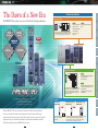
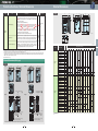
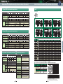
This type consists of the converter and inverter circuits.The
inverter can be operated using a commercial power supply.
* DC power can also be supplied without using the converter circuit.
Features
Easier arrangement for small-scale
- Built-in converter (rectifier)
system
- Built-in control circuit
- External DC reactor as standard*
- DC input is available.
Common
Standard
Specifications Specifications
The FRENIC-VG is creating a new era via the industry-leading performance.
Product introduction
Terminal
Functions
The Dawn of a New Era
* Available for 75kW or higher
capacity models
Stack type
CONCEPT
Inverter (Stack Type)
Converter section
Inverter section
Power
supply
M
INV
M
The converter and inverter sections are separately
set in this type.The converter (diode stack) or PWM
converter is required depending on the intended
use. Moreover, a combination of inverters can be
used with one converter.
High performance enabled by the comprehensive use of Fuji technology.
Easy maintenance for the end-user.
Maintains safety and protects the environment.
Opens up possibilities for the new generation.
inverter on the market. In addition to basic performance, this model features the following
dramatic improvements: support for previously difficult applications due to technical and capability
limitations, easier, more user-friendly maintenance, and environmental friendliness and safety.
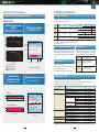
Diode rectifier
RHD-D series
Features
- DC supply enables the multi-drive arrangement
- Energy can be shared within DC bus lines.
- Downsized panel
- Large-capacity system is easily built.
- Maintainability
PMW converter (Stack Type)
PMW converter (Unit Type)
RHC-D series*
RHC-C series*
CNV
NEW
CNV
CNV
Available
soon
This converter is used where no
electric power regeneration
is required.
This converter is used where electric power regeneration or harmonic
control is required. Peripheral devices are separately required.
* D series and C series differ in form but show identical function and performance.
Please use them according to the installation space and purposes.
Fuji Electric proudly introduces the FRENIC-VG to the world.
2
- The converter (rectifier) is separately set.
- External control circuit
- Built-in DC reactor
Converter
NEW
With the FRENIC-VG, Fuji has concentrated its technologies to deliver the best-performing
Structure
3
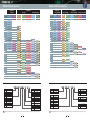
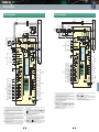
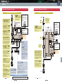
Wiring Diagram
NEW
Options
Unit type
External Dimensions Dedicated Motor
of Dedicated Motors Specifications
Names and
Functions of Parts
External
Dimensions
A Wide Range
of Applications
Guidelines for
Delivery Period
Suppressing Harmonics
and Code
Easier
Maintenance
Protective
Functions
NEW
Inverter (Unit Type)
Converter section
Structure
Inverter section
Power
supply
M
INV
Improved
Control
Performance
Adaptation to
Environment
and Safety
This type consists of the converter and inverter circuits.The
inverter can be operated using a commercial power supply.
* DC power can also be supplied without using the converter circuit.
Features
Easier arrangement for small-scale
- Built-in converter (rectifier)
system
- Built-in control circuit
- External DC reactor as standard*
- DC input is available.
Common
Standard
Specifications Specifications
The FRENIC-VG is creating a new era via the industry-leading performance.
Product introduction
Terminal
Functions
The Dawn of a New Era
* Available for 75kW or higher
capacity models
Stack type
CONCEPT
Inverter (Stack Type)
Converter section
Inverter section
Power
supply
M
INV
M
The converter and inverter sections are separately
set in this type.The converter (diode stack) or PWM
converter is required depending on the intended
use. Moreover, a combination of inverters can be
used with one converter.
High performance enabled by the comprehensive use of Fuji technology.
Easy maintenance for the end-user.
Maintains safety and protects the environment.
Opens up possibilities for the new generation.
inverter on the market. In addition to basic performance, this model features the following
dramatic improvements: support for previously difficult applications due to technical and capability
limitations, easier, more user-friendly maintenance, and environmental friendliness and safety.
Diode rectifier
RHD-D series
Features
- DC supply enables the multi-drive arrangement
- Energy can be shared within DC bus lines.
- Downsized panel
- Large-capacity system is easily built.
- Maintainability
PMW converter (Stack Type)
PMW converter (Unit Type)
RHC-D series*
RHC-C series*
CNV
NEW
CNV
CNV
Available
soon
This converter is used where no
electric power regeneration
is required.
This converter is used where electric power regeneration or harmonic
control is required. Peripheral devices are separately required.
* D series and C series differ in form but show identical function and performance.
Please use them according to the installation space and purposes.
Fuji Electric proudly introduces the FRENIC-VG to the world.
2
- The converter (rectifier) is separately set.
- External control circuit
- Built-in DC reactor
Converter
NEW
With the FRENIC-VG, Fuji has concentrated its technologies to deliver the best-performing
Structure
3
Wiring Diagram
NEW
Options
Unit type
External Dimensions Dedicated Motor
of Dedicated Motors Specifications
Names and
Functions of Parts
External
Dimensions
A Wide Range
of Applications
Guidelines for
Delivery Period
Suppressing Harmonics
and Code
Easier
Maintenance
Protective
Functions
NEW
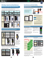
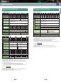
Improved Control Performance
A Wide Range of Applications
Realizes the industry-leading control performance
Ratings for intended use
The operation mode for the motor is selected according to motor load condition. Motors larger by one or two frames can be driven
with medium load (MD) and light load (LD) use.
Induction motor
Achieved speed response
of 600 Hz
Follow-up characteristics
under impact load
(Tested with a dedicated motor with PG under vector control with
speed sensor: about six times greater than our conventional model)
25.0
dB
Specification Applied load
HD
High Duty
Spec
Powerful drive at low noise
MD
Middle Duty
Spec
Can drive motors of frames
one size larger *1
LD
dBMg
100%
Torque current
command value
-25.0
dB 1
10
100
Actual speed
value
0.0
deg
100r/min
Motor current
Phase
(deg)
Low Duty
Spec
Can drive motors of frames
one or two sizes larger *1
Applicable overload rating
10
100
1000
Load ON(100%)
Frequency Hz
Load OFF(0%)
FRN7.5VG1S-2J(600Hz, -3dB)
FRN7.5VG7S-2(105Hz, -3dB)
* With the stack type, "100 Hz" is achieved.
Uneven rotation
reduced by one-third
Speed and torque characteristics
400V
3.7 to 630
Stack Type*2
400V
110 to 450 *2
200V
37 to 110
400V
37 to 710
30 to 800
37 to 1000
Note)A DCL may be selected according to applicable specifications.
*1 This varies depending on motor specifications and power supply voltage (unit type only).
*2 Carrier frequency becomes 2kHz.
Control method
Not only the induction motors but also the synchronous motors
can be driven, and for the induction motors, you can select the
most suitable control method according to your individual needs.
Having a standard built-in brake circuit (with 200V 55kW or less and
400V 160KW or less), is useful when applying the inverter to the vertical
transfer machine, which is frequently used under the regenerative load.
Target motors
Control method
Induction motor
-Vector control with speed sensor
-Speed sensorless vector control
-V/f Control
Synchronous motor
- Vector control with speed sensor
(including pole position detection)
A wide range of options
- Providing options supporting various interfaces such as high-speed serial communications
- Options can be used by just inserting them into the connectors inside the inverter. Up to five cards can be mounted.
Under vector control with sensor
* Compared with our conventional models
0.75 to 90
Unit type:120% 1min
Stack type:110% 1min
- Position control by built-in APC
- The ABS encoder I/F option card with 17-bit high resolution has been prepared.
- Pulse train input enabled (optional)
- The option card for the SX and E-SX bus I/F has been prepared.
FRN37VG1S-4J, at 500r/min operation
FRN7.5VG5S-2(54Hz, -3dB)
200V
150% 1min
Servo function
0.5s
Unit Type
200V
* Unit type only
-360
deg 1
Applicable motor capacity [kW]
Power supply
voltage
Current: 150% 1min/200% 3sec
A standard built-in brake circuit with expanded capacity range
1000
Frequency Hz
Feature
(For details, please contact us because the combination of the optional cards has some restrictions.)
Categoly
Analog card
FRN37VG1S-4J
Digital card (for 8-bit bus)
0.5r/min
Axial torque (%)
0.5r/min
OPC-VG1-FV*1
Analog input/output interface expansion card
OPC-VG1-AIO
Digital input
OPC-VG1-DI
OPC-VG1-DIO
PG interface card
50
-50
1000
2000
3000
Rotation speed
(r/min)
PG card for synchronous motor drive
OPC-VG1-PG
Open collector
OPC-VG1-PGo
ABS encoder with 17-bit high resolution
OPC-VG1-SPGT
Line driver
OPC-VG1-PMPG
Open collector
OPC-VG1-PMPGo
OPC-VG1-TL
CC-Link communication card
OPC-VG1-CCL
High-speed serial communication card (for UPAC)
OPC-VG1-SIU*1
SX bus communication card
OPC-VG1-SX
E-SX bus communication card
OPC-VG1-ESX
User programming card
OPC-VG1-UPAC*1
PROFINET-IRT communication card
OPC-VG1-PNET*1
Safety card
Functional safety card
OPC-VG1-SAFE
Field bus interface card
PROFIBUS-DP communication card
OPC-VG1-PDP*1
DeviceNet communication card
OPC-VG1-DEV*1
Terminal block for high-speed communications
OPC-VG1-TBSI
-100
Digital card (for 16-bit bus)
FRN37VG1S-4J
Control circuit terminal
*1 comming soon
4
+5V line driver
T-Link communication card
-150
at 30r/min operation
F/V converter
100
0
Type
OPC-VG1-SN*1
Digital input
150
Conventional model FRN37VG7S-4
Name
Synchronized interface
5
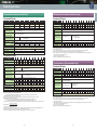
A Wide Range of Applications and Easier Maintenance
Product Arrangement and Easier Change of the Inverters (Stack type)
Upgraded PC loader functions
The inverters (stack type) have an arrangement with consideration for the installation of the product into the panel and easier change.
The inverters (stack type) (132 to 315 kW) can easily be installed or changed because they have wheels.
With the inverters (stack type) (630 to 800 kW), stacks are divided for each output phase (U, V and W), which has realized the lighter weight.
30 to 110
Type
FRN30SVG1S-4 to
FRN110SVG1S-4
FRN132SVG1S-4 to
FRN315SVG1S-4
FRN630BVG1S-4 to
FRN800BVG1S-4
Categoly
Single unit
Single unit
Stack by phase
Wheels
Not provided
Provided
Provided
630 to 800
P
P
P
N
N
N
PC Loader can be used via the USB connector (mini B) provided on the front cover.
FRENIC-VG
PC
USB Mini B
connector
- The front cover does not have to be removed.
- No RS-485 converter is needed.
Nominal applied motor capacity
[kW] (MD spec)
132 to 315
Easier Maintenance and Greater Reliability
USB cable
Connection available
in the inverter front.
- Commercial cables can be used.
[Easy edit and detail monitor]
[Fault diagnosis using the trace back function]
Data editing and detailed data monitor analysis operations
are much easier than with a conventional PC loader.
Edited on the trace screen on the loader
Function code setting User-defined displays (customized displays),
Arrangement
data explanation display for each code.
U-phase V-phase W-phase
U,V,W
IM
IM
The weight of one stack is reduced (50 kg or
less) to give consideration to replacement work.
Maintenance
Trace function Real-time trace: for long-term monitoring
U,V,W
Type
FRN30SVG1S-4
FRN37SVG1S-4
FRN45SVG1S-4
FRN55SVG1S-4
FRN75SVG1S-4
FRN90SVG1S-4
FRN110SVG1S-4
Weight [kg]
28
- Internal data, time and date around the fault are recorded.
The real-time clock (clock function) is built-in as standard.
- Data are backed up by battery.
M
The models where each stack
is heavy have wheels in order
to change the stacks easily.
A lifter for replacement*1
is available.
35
43
Lifter (Conceptual view)
Trim weight by dividing the
stack into 3 parts by each
output phase (U, V and W).
In the event of a breakdown,
only the target phase needs
to be replaced with a new one.
The stack to be replaced
should be an exclusive part.
- Trace waveform can be checked on the PC loader
Fault
Multifunctional the Keypad
How to expand the capacity range of the inverters (stack type)
- The back-light is incorporated in the LCD panel, which
enables the easy inspection in the dark control panel.
Direct parallel connection system and multiwinding motor drive system are provided for driving a large capacity motor.
Multiwinding motor drive system
Single-winding motor
Multiwinding motor
(Exclusive use motor where winding separates off)
Restriction of
wiring length
The minimum wiring length (L)
varies with the capacity.
There is no particular limit.
Engine cut off
operation*2
Enabled
Enabled
(However, the wiring should be switched over.)
2 to 3 inverters
2 to 6 inverters
Drive motor
Features
Number of inverters to be connected
When 2 inverters
are connected
P
When 2 inverters
are connected
N
Arrangement diagram
*1) OPC-VG1-TBSI is separately required.
*2) Engine cut off operation. If a stack fails in case of direct
parallel connection, the operation continues with lower
output power using the stacks that have not failed
200kW
200kW
Fault
U,V,W
U,V,W
N
355kW
P,N
P,N
P,N
*1
*1
*1
*1
U,V,W
U,V,W
U,V,W
U,V,W
IM
IM
Example) If one inverter goes wrong when 200kW x
2 inverters are driving a 355kW motor, you
can continue operation with the 200kW
inverter (capacity of one inverter).
(Note) To start the engine cut off operation, consideration is needed to
the switch over operation of PG signals or motor constants and
sequence circuit. For details, refer to the operation manual.
IM
Example of the arrangement when direct parallel connection is used
2 direct parallel connection systems
Stacks arrangement examples
3 direct parallel connection systems
P
P
N
N
355
FRN200SVG1S-4
×2
P,N
P,N
P,N
P,N
P,N
400
FRN220SVG1S-4
×2
*1
*1
*1
*1
*1
500
FRN280SVG1S-4
×2
U,V,W
U,V,W
U,V,W
U,V,W
U,V,W
630
FRN220SVG1S-4
×3
710
FRN280SVG1S-4
×3
800
FRN280SVG1S-4
×3
IM
*1) OPC-VG1-TBSI is separately required.
6
The function codes can be copied to other inverters easily.
(Three patterns of function codes can be stored.) Copying
data in advance reduces restoration time when problems
occur, by replacing the Keypad when changing the unit.
IM
- JOG (jogging) operation can be executed using
the Keypad.
- The HELP key displays operation guidance.
More reliable functions
Alarm severity selection
Detailed data are stored for
the last four alarms, including:
Alarm severity (serious and minor) can be selected, eliminating
the risk of critical facility stoppage due to a minor fault.
OU
Time of occurrence
2011/01/01
12:36:45
Time of occurrence
30-relay
output
OC
2011/01/01
LU
- Time to sound alarm
12:36:45 N* =1500.0r/m
Time of occurrence
- Speed setting value
N =1500.0r/m
2011/01/02
OC
f *=50.0Hz
12:36:45 N* =1500.0r/m
- Detection speed value
Time of occurrence
TRQ= 90%
N =1500.0r/m
2011/01/05
- Torque command value
f *=50.0Hz
12:36:45 N* =1500.0r/m
TMP = 43℃
- Temperature
TRQ= Iout
90%= 251.6A
N =1500.0r/m
(heat sink, internal temperature)
Parallel connection of the 2 or 3 inverters with the same capacity enables larger capacity and system redundancy.
A typical combination is shown in the table below, but other combinations are also available.
Combination example for direct parallel connection
- Enhanced copy function
The Keypad can be remotely operated by
extending the cable length at the RJ-45 connector.
Save alarm data
P
P,N
L
Nominal applied motor capacity
[kW] (MD spec)
- Remote control operation is available.
- Wide 7-segment LED ensures easy view.
Direct parallel connection system
*The paid-for loader software (WPS-VG1-PCL) supports real-time
tracing and historical tracing. Trace data can be stored in the memory
even while the power is off. (With 22 kW or lower power loaders,
support is possible as an option [memory back-up battery].)
*Battery: 30kW or more (built-in as standard), up to 22kW (available as option: OPK-BP)
*1) The lifter will be available soon.
System
Historical trace: for detailed data diagnosis for
short periods
Trace back: for fault analysis (last three times)
- Accumulated operation time
- Output current detection value
- Magnetic-flux reference value
- I/O status
Y-terminal
output
Inverter
output
Selection
Operation
No output
Motor overload,
Provided
continued Can be selected
communications error, (minor fault)
for each function.
DC fan lock, etc.
Output
Not provided Shut off
Blown fuse, excessive current,
ground fault, etc.
Vout 35℃
= 190V
f *=50.0Hz
TMP = N* =1500.0r/m
FLX*
= 100%
TRQ= Iout
90%= 256.2A
N =1500.0r/m
Vout 55℃
= 200V
f *=50.0Hz
TMP = FLX*
= 100%
TRQ= Iout
90%= 180.0A
Output
Not provided
Shut off
Fixed
PG fault diagnosis
- The PG interface circuit incorporated as standard detects disconnection
of the power supply line as well as the PG signal line.
- Operation can be continued in sensorless mode during PG disconnection
or fault. (Soon to be supported)
Vout 45℃
= 132V
TMP = FLX*
= 100%
Iout = 210.6A
Vout = 160V
FLX* = 100%
Old model: The inverter was stopped by a trip and the motor ran freely.
New model: The mode is automatically switched to sensorless vector control mode when a
PG fault is detected, minimizing effect to the machined products.
- The number of alarm data to be stored has been increased from the conventional model.
Thanks to the real-time clock function built-in as standard, the
complete data of the latest and last 3 alarm occurences is stored:
time, speed command, torque, current and others. This enables
machine units to be checked for abnormalities.
(Sensorless control shows lower control performance than vector control with a speed sensor. Combine equipment
and machines to be used and check their operation in advance for insufficient torque at low speed, etc.)
- A mode was added that judges if it is a PG fault or a fault on the inverter side
Simulated output mode is provided at the PG pulse output terminal (FA and FB).
Operation can be checked by connecting this to the PG input terminal.
As for previous model, new alarm data overwrote and deleted existing alarm data.
This is solved with the new VG model.
7
Easy wiring (removable control terminal block)
Easy change of the cooling fan
Unit Type
Inverter body
Fan body
The cooling fan can easily be changed
without removing the front cover and printed
board.
- Restoration time for updating equipment, problem occurrence, and inverter replacement has been drastically reduced. Just mount the wired terminal block board to the replaced inverter.
Unit Type
Inverter body
Stack Type
- The terminal block can be connected to the inverter after control wiring work is completed. Wiring work is simplified.
Fan body
The cooling fan installed at the top can easily
be changed without drawing the stacks.
However, for the 220 to 315kW inverter,
remove the 2 connection bars from the DC
side and change the cooling fan.
Stack Type
Adaptation to Environment and Safety
Conforms to safety standards (Soon to be supported)
Enhanced environmental resistance
- The functional safety (FS) function STO that conforms to the
FS standard EN61800-5-2 is incorporated as standard.
Environmental resistance has been enhanced compared to
conventional inverters.
(1) Environmental resistance of cooling fan has been enhanced.
(2) Ni and Sn plating are employed on copper bars.
- The FS functions STO, SS1, SLS and SBC that conform to FS
standard EN61800-5-2 can be also available by installing the option
card OPC-VG1-SAFE. (Available only when controlling the motor
using feedback encoder (closed loop).)
Environmental resistance has been enhanced on the FRENIC-VG
compared to conventional models; however, the following environments
should be examined based on how the equipment is being used.
Safety function STO: Safe Torque Off
This function shuts off the output of the inverter (motor output torque) immediately.
Safety function SS1: Safe Stop 1
This function decreases the motor speed to shut down the motor output torque (by STO FS
function) after the motor reaches the specified speed or after the specified time has elapsed.
a. Sulfidizing gas (present in some activities such as tire manufacturers,
paper manufacturers, sewage treatment, and the textile industry)
b. Conductive dust and foreign particles (such as with metal
processing, extruding machines, printing machines, and waste treatment)
c. Others: under unique environments not included
under standard environments
Safety function SLS: Safely Limited Speed
This function prevents the motor from rotating over the specified speed.
Safety function SBC: Safe Brake Control
This function outputs a safe signal of the motor brake control.
Components with a longer service life
For the various consumable parts inside the inverter, their
designed lives have been extended to 10 years.
This also extended the equipment maintenance cycles.
Life-limited component
Cooling fan
Life conditions
Ambient temperature: 40°C*2, load factor: 100% (HD spec), 80% (MD and LD specs)
Smoothing capacitor on main circuit
RoHS Directive compliance
FRENIC-VG complies with European regulations that limit the use of specific hazardous substances (RoHS) as a standard.
Six hazardous substances
About RoHS
Lead, mercury, cadmium, hexavalent chromium, polybrominated
biphenyl (PBB), polybrominated diphenyl ether (PBDE)
*Does not apply to the parts of some inverter models.
Enhanced lifetime alarm
Directive 2002/95/EC, promulgated by the European Parliament and
European Council, limits the use of specific hazardous substances
included in electrical and electronic devices.
Useful functions for test run and adjustment
- Lifetime alarms can be checked rapidly on the Keypad and
PC loader (optional).
- Facility maintenance can be performed much easier thanks
to lifetime alarms.
- Customization of functions for test run and adjustment
(Individual items on the loader can be set to be displayed or not.)
- Each communications I/O map input/output status is displayed (for PLC software
debug) on the loader or the keypad (keypad to be supported soon).
- Simulated fault alarm issued by a special function on the Keypad
Items
No. of inverter
starts (times)
10 years
Electrolytic capacitors on PCB
*1) The planned life is determined by calculation, and is not the guaranteed value.
*2) For the stack type, the ambient temperature is 30°C.
Inverter accumulated
time (h)
Design lifetime*1
Contact Fuji before using the product in environments such as
those indicated above.
- Monitor data hold function
Input/output terminal inverting stack type
If there is no space on the lower side, an input/output inverting
stack type is available, with the motor terminals located on the
upper side and the DC bus terminals located on the lower side
(only for the 220kW inverter). Contact us for specific details
AC
terminal
block
R S T
U V W
- Simulated operation mode
Simulated connection allows the inverter to be operated with internal parts in the
same way as if they were connected to the motor, without actually being connected.
Facility maintenance warning Inverter lifetime
Accumulated time (h) alarm information
is displayed.
No. of starts (times)
This has the opposite
input/output location
of the standard stack
type.
M
- The externally input I/O monitor and PG pulse states can be
checked on the Keypad.
P.N
DC bar
terminal
- ASR auto tuning (to be supported soon on the keypad).
Converter
8
MC
9
Inverter
Wheels
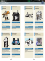
Application Examples
Large crane and
overhead crane
Application to plants
Feeding part of semiconductor
manufacturing device, wire saw
Test equipment
for automobiles
Electric room
M
Feed
winder
Material
M
Dancer
M
Traverse
M
Operation
room
M
M
Traverse
main Spindle
Container
M
Dancer
M
Monitoring room
unwinder
Travel equipment
Control with high speed and high accuracy
High reliability
In addition to high speed and high accuracy, VG contributes to stable facility
operation with high reliability and long service life. The trace back function
makes diagnosing the cause of problems easy when an abnormality arises.
VG supports your facility with long life service and high
reliability.
The trace back function allows easy fault diagnosis.
Bus system support
Bus system support
Centralized control and monitoring are achieved by
supporting various fieldbuses.
The bus system is supported to allow centralized control
of elevation, traverse, and trolley, as well as centralized
monitoring of running conditions.
Servo press: large size for automobiles, small size for
machines such as crimping terminal processing machines
Winding equipment
(paper and metal)
Tension control
Position control
Tension-type winding control capability with high
accuracy torque control has been improved.
Dancer-type winding control capability by the speed
control with high speed response has been improved.
The press position is controlled based on an instantaneous
position command given by the upper order CNC.
Control with high responsibility contributes to shortening of
the operation cycle.
High-speed response control
Smooth torque characteristic
High-speed rotation and torque control with high
response are available for engine and transmission tests.
The smooth drive characteristic in which torque ripple is
suppressed contributes to machining quality.
System support
System support
The system can be supported in cases such as the
vehicle body inertia simulation function for a brake test
apparatus by combining with the controller.
The system becomes more simple and highly efficient by
using same bus system for main axis (spindle) and the other
axes (traverse and winding) driven by small capacity servos.
Shipboard winch
Flying shear
(Cutting while moving)
Position control
High reliability and tension control
Position control is performed according to the position
command given by the upper order CNC.
The machine cuts the material while moving at the same
speed (as the material).
Torque is controlled up to extra low speed using the
sensorless feature.
Stable drive is maintained against load variation caused
by waves.
System support
Precision synchronization control
System support
The controller that calculates winding diameter achieves
constant tension control.
Large machines are driven with several motors to increase thrust.
Precision synchronization control of several inverters and motors
using the high-speed bus system can be applied.
10
The system is configured by an upper controller that
calculates synchronous operation between the material
feed axis, cutter feed axis and cut axis.
11
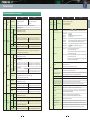
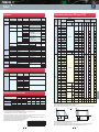
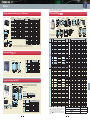
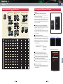
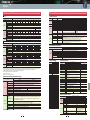
Model variation (converter)
Inverter (Stack Type)
Unit Type (PWM)
Unit Type (PWM)
Stack Type (PWM)
Diode rectifier [soon-to-be-released]
Nominal applied motor
(kW)
HD
(150%, 1 min./200%, 3 sec.)
LD
(120%, 1 min.)
HD
(150%, 1 min./200%, 3 sec.)
MD
(150%, 1 min.)
LD
(120%, 1 min.)
MD
(150%, 1 min.)
LD
(110%, 1 min.)
Nominal applied motor
(kW)
MD(CT)
(150%, 1 min.)
LD(VT)
(120%, 1 min.)
MD(CT)
(150%, 1 min.)
LD(VT)
(120%, 1 min.)
MD
(150%, 1 min.)
LD
(110%, 1 min.)
MD
(150%, 1 min.)
LD
(110%, 1 min.)
Applied load
High Duty Spec
Low Duty Spec
High Duty Spec
Middle Duty Spec
Low Duty Spec
Middle Duty Spec
Low Duty Spec
Applied load
High Duty Spec
Low Duty Spec
High Duty Spec
Low Duty Spec
Middle Duty Spec
Low Duty Spec
Middle Duty Spec
Low Duty Spec
0.75
FRN0.75VG1S-2
7.5
RHC7.5-2C
1.5
FRN1.5VG1S-2
11
RHC11-2C
RHC7.5-2C
RHC11-4C
RHC7.5-4C
2.2
FRN2.2VG1S-2
15
RHC15-2C
RHC11-2C
RHC15-4C
RHC11-4C
3.7
FRN3.7VG1S-2
FRN3.7VG1S-4
18.5
RHC18.5-2C
RHC15-2C
RHC18.5-4C
RHC15-4C
5.5
FRN5.5VG1S-2
FRN5.5VG1S-4
22
RHC22-2C
RHC18.5-2C
RHC22-4C
RHC18.5-4C
7.5
FRN7.5VG1S-2
FRN7.5VG1S-4
30
RHC30-2C
RHC22-2C
RHC30-4C
RHC22-4C
11
FRN11VG1S-2
FRN11VG1S-4
37
RHC37-2C
RHC30-2C
RHC37-4C
RHC30-4C
15
FRN15VG1S-2
FRN15VG1S-4
45
RHC45-2C
RHC37-2C
RHC45-4C
RHC37-4C
FRN18.5VG1S-2
FRN18.5VG1S-4
55
RHC55-2C
RHC45-2C
RHC55-4C
RHC45-4C
22
FRN22VG1S-2
FRN22VG1S-4
75
RHC75-2C
RHC55-2C
RHC75-4C
RHC55-4C
30
FRN30VG1S-2
FRN30VG1S-4
90
RHC90-2C
RHC75-2C
RHC90-4C
RHC75-4C
37
FRN37VG1S-2
FRN30VG1S-2
FRN37VG1S-4
FRN30VG1S-4
FRN37SVG1S-4
FRN30SVG1S-4
110
RHC90-2C
RHC110-4C
RHC90-4C
45
FRN45VG1S-2
FRN37VG1S-2
FRN45VG1S-4
FRN37VG1S-4
FRN45SVG1S-4
FRN37SVG1S-4
132
RHC132-4C
RHC110-4C
RHC132S-4D
55
FRN55VG1S-2
FRN45VG1S-2
FRN55VG1S-4
FRN45VG1S-4
FRN55SVG1S-4
FRN45SVG1S-4
160
RHC160-4C
RHC132-4C
RHC160S-4D
RHC132S-4D
75
FRN75VG1S-2
FRN55VG1S-2
FRN75VG1S-4
FRN55VG1S-4
FRN75SVG1S-4
FRN55SVG1S-4
200
RHC200-4C
RHC160-4C
RHC200S-4D
RHC160S-4D
90
FRN90VG1S-2
FRN75VG1S-2
FRN90VG1S-4
FRN75VG1S-4
FRN90SVG1S-4
FRN75SVG1S-4
220
RHC220-4C
RHC200-4C
RHC220S-4D
RHC200S-4D
FRN90VG1S-2
FRN110VG1S-4
FRN90VG1S-4
FRN90VG1S-4
FRN110SVG1S-4
FRN90SVG1S-4
280
RHC280-4C
RHC220-4C
RHC280S-4D
FRN132VG1S-4
FRN110VG1S-4
FRN110VG1S-4
FRN132SVG1S-4
FRN110SVG1S-4
315
RHC315-4C
RHC280-4C
RHC315S-4D
FRN160SVG1S-4
FRN132SVG1S-4
355
RHC355-4C
RHC315-4C
RHC400-4C
RHC355-4C
RHC400-4C
132
Terminal
Functions
Protective
Functions
RHC280S-4D
FRN160VG1S-4
FRN132VG1S-4
FRN132VG1S-4
200
FRN200VG1S-4
FRN160VG1S-4
FRN160VG1S-4
FRN200SVG1S-4
FRN160SVG1S-4
400
220
FRN220VG1S-4
FRN200VG1S-4
FRN200VG1S-4
FRN220SVG1S-4
FRN200SVG1S-4
450
FRN250SVG1S-4
FRN220SVG1S-4
500
RHC500-4C
FRN280SVG1S-4
FRN250SVG1S-4
630
RHC630-4C
FRN315SVG1S-4
FRN280SVG1S-4
710
RHC710B-4D
RHC630B-4D
FRN315SVG1S-4
800
RHC800B-4D
RHC710B-4D
FRN280VG1S-4
315
FRN315VG1S-4
FRN280VG1S-4
355
FRN355VG1S-4
FRN315VG1S-4
FRN280VG1S-4
400
FRN400VG1S-4
FRN355VG1S-4
FRN315VG1S-4
FRN400VG1S-4
FRN355VG1S-4
450
FRN220VG1S-4
FRN500VG1S-4
FRN400VG1S-4
630
FRN630VG1S-4
FRN500VG1S-4
FRN630BVG1S-4
FRN630VG1S-4
FRN710BVG1S-4
FRN630BVG1S-4
FRN800BVG1S-4
FRN710BVG1S-4
710
800
1000
RHD315S-4D
RHC630B-4D
RHC800B-4D
1000
500
RHD315S-4D
Wiring Diagram
FRN220VG1S-4
280
RHD200S-4D
RHC315S-4D
160
250
RHD200S-4D
External Dimensions Dedicated Motor
of Dedicated Motors Specifications
110
FRN30SVG1S-4
FRN800BVG1S-4
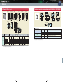
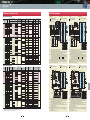
How to read the model number
Description of converter type
FRN 30 S VG 1 S - 4 J
Code
FRN
Series name
FRENIC Series
Code
0.75
1.5
2.2
Nominal applied motor capacity
0.75kW
1.5kW
2.2kW
800
800kW
Code
None
S
B
Form
Unit type
Standard stack
Stack by phase
RHC 315 S - 4 D J
Code
J
E
C
Destination / Instruction Manual
Japanese
English
Chinese
Code
RHC
RHD
Series name
PMW converter
Diode rectifier
Code
2
4
Input power source
Three-phase 200V
Three-phase 400V
Code
132
Nominal applied motor capacity
132kW
800
800kW
Code
None
S
B
Form
Unit type
Standard stack
Stack by phase
Code
S
Structure
Standard
Code
1
Developed inverter series
1 Series
Code
VG
Application range
High performance vector control
Caution! The product detail described in this document is intended for selecting a model. When using a product, read the Instruction Manual carefully and use the product properly.
12
Options
18.5
RHC7.5-4C
Common
Standard
Specifications Specifications
Unit Type
400V Series
External
Dimensions
Unit Type
200V Series
Names and
Functions of Parts
400V Series
Code*
J
E
C
Destination / Instruction Manual
Japanese
English
Chinese
* This item is available only with the D series.
Code
C
D
Developed inverter series
C Series
D Series
Code
2
4
Input power source
Three-phase 200V
Three-phase 400V
Caution! The product detail described in this document is intended for selecting a model. When using a product, read the Instruction Manual carefully and use the product properly.
13
Warranty
200V Series
Guidelines for
Delivery Period
Suppressing Harmonics
and Code
Model variation (Inverter)
Model variation (converter)
Inverter (Stack Type)
Unit Type (PWM)
Unit Type (PWM)
Stack Type (PWM)
Diode rectifier [soon-to-be-released]
Nominal applied motor
(kW)
HD
(150%, 1 min./200%, 3 sec.)
LD
(120%, 1 min.)
HD
(150%, 1 min./200%, 3 sec.)
MD
(150%, 1 min.)
LD
(120%, 1 min.)
MD
(150%, 1 min.)
LD
(110%, 1 min.)
Nominal applied motor
(kW)
MD(CT)
(150%, 1 min.)
LD(VT)
(120%, 1 min.)
MD(CT)
(150%, 1 min.)
LD(VT)
(120%, 1 min.)
MD
(150%, 1 min.)
LD
(110%, 1 min.)
MD
(150%, 1 min.)
LD
(110%, 1 min.)
Applied load
High Duty Spec
Low Duty Spec
High Duty Spec
Middle Duty Spec
Low Duty Spec
Middle Duty Spec
Low Duty Spec
Applied load
High Duty Spec
Low Duty Spec
High Duty Spec
Low Duty Spec
Middle Duty Spec
Low Duty Spec
Middle Duty Spec
Low Duty Spec
0.75
FRN0.75VG1S-2
7.5
RHC7.5-2C
1.5
FRN1.5VG1S-2
11
RHC11-2C
RHC7.5-2C
RHC11-4C
RHC7.5-4C
2.2
FRN2.2VG1S-2
15
RHC15-2C
RHC11-2C
RHC15-4C
RHC11-4C
3.7
FRN3.7VG1S-2
FRN3.7VG1S-4
18.5
RHC18.5-2C
RHC15-2C
RHC18.5-4C
RHC15-4C
5.5
FRN5.5VG1S-2
FRN5.5VG1S-4
22
RHC22-2C
RHC18.5-2C
RHC22-4C
RHC18.5-4C
7.5
FRN7.5VG1S-2
FRN7.5VG1S-4
30
RHC30-2C
RHC22-2C
RHC30-4C
RHC22-4C
11
FRN11VG1S-2
FRN11VG1S-4
37
RHC37-2C
RHC30-2C
RHC37-4C
RHC30-4C
15
FRN15VG1S-2
FRN15VG1S-4
45
RHC45-2C
RHC37-2C
RHC45-4C
RHC37-4C
FRN18.5VG1S-2
FRN18.5VG1S-4
55
RHC55-2C
RHC45-2C
RHC55-4C
RHC45-4C
22
FRN22VG1S-2
FRN22VG1S-4
75
RHC75-2C
RHC55-2C
RHC75-4C
RHC55-4C
30
FRN30VG1S-2
FRN30VG1S-4
90
RHC90-2C
RHC75-2C
RHC90-4C
RHC75-4C
37
FRN37VG1S-2
FRN30VG1S-2
FRN37VG1S-4
FRN30VG1S-4
FRN37SVG1S-4
FRN30SVG1S-4
110
RHC90-2C
RHC110-4C
RHC90-4C
45
FRN45VG1S-2
FRN37VG1S-2
FRN45VG1S-4
FRN37VG1S-4
FRN45SVG1S-4
FRN37SVG1S-4
132
RHC132-4C
RHC110-4C
RHC132S-4D
55
FRN55VG1S-2
FRN45VG1S-2
FRN55VG1S-4
FRN45VG1S-4
FRN55SVG1S-4
FRN45SVG1S-4
160
RHC160-4C
RHC132-4C
RHC160S-4D
RHC132S-4D
75
FRN75VG1S-2
FRN55VG1S-2
FRN75VG1S-4
FRN55VG1S-4
FRN75SVG1S-4
FRN55SVG1S-4
200
RHC200-4C
RHC160-4C
RHC200S-4D
RHC160S-4D
90
FRN90VG1S-2
FRN75VG1S-2
FRN90VG1S-4
FRN75VG1S-4
FRN90SVG1S-4
FRN75SVG1S-4
220
RHC220-4C
RHC200-4C
RHC220S-4D
RHC200S-4D
FRN90VG1S-2
FRN110VG1S-4
FRN90VG1S-4
FRN90VG1S-4
FRN110SVG1S-4
FRN90SVG1S-4
280
RHC280-4C
RHC220-4C
RHC280S-4D
FRN132VG1S-4
FRN110VG1S-4
FRN110VG1S-4
FRN132SVG1S-4
FRN110SVG1S-4
315
RHC315-4C
RHC280-4C
RHC315S-4D
FRN160SVG1S-4
FRN132SVG1S-4
355
RHC355-4C
RHC315-4C
RHC400-4C
RHC355-4C
RHC400-4C
132
Terminal
Functions
Protective
Functions
RHC280S-4D
FRN160VG1S-4
FRN132VG1S-4
FRN132VG1S-4
200
FRN200VG1S-4
FRN160VG1S-4
FRN160VG1S-4
FRN200SVG1S-4
FRN160SVG1S-4
400
220
FRN220VG1S-4
FRN200VG1S-4
FRN200VG1S-4
FRN220SVG1S-4
FRN200SVG1S-4
450
FRN250SVG1S-4
FRN220SVG1S-4
500
RHC500-4C
FRN280SVG1S-4
FRN250SVG1S-4
630
RHC630-4C
FRN315SVG1S-4
FRN280SVG1S-4
710
RHC710B-4D
RHC630B-4D
FRN315SVG1S-4
800
RHC800B-4D
RHC710B-4D
FRN280VG1S-4
315
FRN315VG1S-4
FRN280VG1S-4
355
FRN355VG1S-4
FRN315VG1S-4
FRN280VG1S-4
400
FRN400VG1S-4
FRN355VG1S-4
FRN315VG1S-4
FRN400VG1S-4
FRN355VG1S-4
450
FRN220VG1S-4
FRN500VG1S-4
FRN400VG1S-4
630
FRN630VG1S-4
FRN500VG1S-4
FRN630BVG1S-4
FRN630VG1S-4
FRN710BVG1S-4
FRN630BVG1S-4
FRN800BVG1S-4
FRN710BVG1S-4
710
800
1000
RHD315S-4D
RHC630B-4D
RHC800B-4D
1000
500
RHD315S-4D
Wiring Diagram
FRN220VG1S-4
280
RHD200S-4D
RHC315S-4D
160
250
RHD200S-4D
External Dimensions Dedicated Motor
of Dedicated Motors Specifications
110
FRN30SVG1S-4
FRN800BVG1S-4
How to read the model number
Description of converter type
FRN 30 S VG 1 S - 4 J
Code
FRN
Series name
FRENIC Series
Code
0.75
1.5
2.2
Nominal applied motor capacity
0.75kW
1.5kW
2.2kW
800
800kW
Code
None
S
B
Form
Unit type
Standard stack
Stack by phase
RHC 315 S - 4 D J
Code
J
E
C
Destination / Instruction Manual
Japanese
English
Chinese
Code
RHC
RHD
Series name
PMW converter
Diode rectifier
Code
2
4
Input power source
Three-phase 200V
Three-phase 400V
Code
132
Nominal applied motor capacity
132kW
800
800kW
Code
None
S
B
Form
Unit type
Standard stack
Stack by phase
Code
S
Structure
Standard
Code
1
Developed inverter series
1 Series
Code
VG
Application range
High performance vector control
Caution! The product detail described in this document is intended for selecting a model. When using a product, read the Instruction Manual carefully and use the product properly.
12
Options
18.5
RHC7.5-4C
Common
Standard
Specifications Specifications
Unit Type
400V Series
External
Dimensions
Unit Type
200V Series
Names and
Functions of Parts
400V Series
Code*
J
E
C
Destination / Instruction Manual
Japanese
English
Chinese
* This item is available only with the D series.
Code
C
D
Developed inverter series
C Series
D Series
Code
2
4
Input power source
Three-phase 200V
Three-phase 400V
Caution! The product detail described in this document is intended for selecting a model. When using a product, read the Instruction Manual carefully and use the product properly.
13
Warranty
200V Series
Guidelines for
Delivery Period
Suppressing Harmonics
and Code
Model variation (Inverter)
MD specification for middle overload (Unit Type)
Three-phase 400V series
3.7
5.5
7.5
11
15
18.5
22
30
37
45
55
Nominal applied motor [kW]
0.75
1.5
2.2
3.7
5.5
7.5
11
15
18.5
22
30
37
45
55
75
90
Rated capacity [kVA] (*1)
1.9
3.0
4.1
6.8
10
14
18
24
28
34
45
55
68
81
107
131
5
8
11
18
27
37
49
63
76
90
119
146
180
215
283
346
Main power
Phase, Voltage, Frequency
3-phase 200 to 230V, 50Hz/60Hz
Auxiliary control power supply
Phase, Voltage, Frequency
Single-phase 200 to 230V, 50Hz/60Hz
(with DCR)
(without DCR)
Rated current [A]
(*7)
Required power supply capacity [kVA] (*8)
Braking method /braking torque
Single phase 200 to 220V, 50Hz
200 to 230V/60Hz (*4)
−
Voltage: +10 to -15% (Voltage unbalance: 2% or less (*6)), Frequency: +5 to -5%
3.2
6.1
8.9
15.0
21.1
28.8
42.2
57.6
71.0
84.4
114
138
167
203
282
334
5.3
9.5
13.2
22.2
31.5
42.7
60.7
80.1
97.0
112
151
185
225
270
−
−
1.2
2.2
3.1
5.2
7.4
10
15
20
25
30
40
48
58
71
98
116
2 to 15
6.2
6.2
6.2
6.2
Protective structure
6.2
6.2
11
11
12
IP20 closed type
VG1S-4J
25
32
42
43
62
IP00 open type (IP20 closed type is available as option)
11
15
18.5 22
30
37
45
55
75
90
110 132 160 200
Nominal applied motor [kW]
3.7
5.5
7.5
11
15 18.5 22
30
37
45
55
75
90
110 132 160 200 220 280 315 355 400 500 630
Rated capacity [kVA] (*1)
6.8
10
14
18
24
45
57
69
85
114 134 160 192 231 287 316 396 445 495 563 731 891
Rated current [A]
9.0 13.5 18.5 24.5 32.0 39.0 45.0 60.0 75.0 91.0 112 150 176 210 253 304 377 415 520 585 650 740 960 1170
29
34
150% of rated current -1min. (*2)
Power supply voltage
Overload current rating
Main power
Phase, Voltage, Frequency
3-phase 380 to 480V, 50Hz/60Hz
Auxiliary control power supply
Phase, Voltage, Frequency
Single phase 380 to 480V, 50Hz/60Hz
Auxiliary input for fan power
Phase, Voltage, Frequency (*5)
220 280 315 355 400 500 630
200% -3s. (*3)
3-phase 380 to 440V/50Hz,
380 to 480V/60Hz (*4)
220
280
315
355
400
Nominal applied motor [kW] (*8)
110
132
160
200
220
250
315
355
400
450
Rated capacity [kVA] (*1)
160
192
231
287
316
356
445
495
563
640
Rated current [A]
210
253
304
377
415
468
585
650
740
840
150% of rated current -1min. (*2)
Main power
Phase, Voltage, Frequency
3-phase 380 to 440V/50Hz,
380 to 480V/60Hz (*3)
Auxiliary control power supply
Phase, Voltage, Frequency
Single phase 380 to 480V, 50Hz/60Hz
Auxiliary input for fan power
Phase, Voltage, Frequency (*4)
Single phase 380 to 440V, 50Hz
380 to 480V/60Hz (*3)
Voltage/frequency variation
Voltage: +10 to -15% (Voltage unbalance: 2% or less (*5)), Frequency: +5 to -5%
Rated current [A]
(*6)
(with DCR)
(without DCR)
Required power supply capacity [kVA] (*7)
210
238
286
357
140
165
199
248
Braking resistor discharge control: 150% braking torque,
Separately installed braking resistor (option)
−
64
94
98
2 to 15
Approx.weight [kg]
6.2
Protective structure
IP20 closed type
6.2
6.2
11
11
11
11
26
31
33
42
62
64
94
98
Three-phase average voltage [V]
271
312
388
436
489
547
Braking resistor discharge control: 150% braking torque,
Separately installed braking resistor (option)
Separately installed braking unit (option)
129
140
245
245
330
−
−
−
−
330
Max. voltage [V] - Min. voltage [V]
Three-phase average voltage [V]
× 67
−
2 to 5
129 140 245 245 330 330 555 555
IP00 open type (IP20 closed type is available as option)
Warranty
× 67
Guidelines for
Delivery Period
Suppressing Harmonics
and Code
Max. voltage [V] - Min. voltage [V]
789
Note 1) The specifications above are established when the function code F80 = 3 (MD specification) is applied.
When used with the MD specification with 90kW or higher, DC reactor is necessary ( to be ordered separately from inverter unit based on the rating)
*1) When the rated output voltage is 440V
*2) When the converted inverter output frequency is less than 1Hz, the inverter may trip earlier in some ambient temperature conditions if the motor is overloaded
*3) When the power supply is 380 to 398V at 50 Hz or 380 to 430V at 60Hz, a connector inside the inverter must be reconnected accordingly.
The output of the inverter with 380V may drop depending on situations.For the detail, refer to the FRENIC-VG User Manual 10.5.
*4) The auxiliary power input is used as an AC fan power input when combining the unit such as high power factor PWM converter with power regenerative function.(Generally not used.)
Note 1) The specification above are established when the function code F80 = 0 (HD specification) is applied.
When used with the HD specification with 75kW or higher, DC reactor is necessary ( to be ordered separately from inverter unit based on the rating)
*1) The rated output voltage is 220V for 200V series and 440V for 400V series.
*2) When the inverter output frequency converter value is 10Hz or less, the inverter may trip early due to overload depending on the conditions such as ambient temperature.
*3) When the inverter output frequency converter value is 5Hz or less, the inverter may trip early due to overload depending on the conditions such as ambient temperature.
*4) 200V series: Make an individual order for 220 to 230V/50Hz.
400V series: The inverters with the power supply of 380 to 398V/50Hz and 380 to 430V/60Hz must be switched using a connector inside the inverter.
The output of the inverter with 380V may drop depending on situations.For the detail, refer to the FRENIC-VG User Manual chapter 10.5.
*5) The auxiliary power input is used as an AC fan power input when combining the unit such as high power factor PWM converter with power regenerative function.(Generally not used.)
*6) Voltage unbalance [%] =
705
Use an AC reactor if the voltage unbalance exceeds 2%.
*6) The value is calculated on assumption that the inverter is connected with a power supply capacity of 10 times the inverter capacity and %X is 5%.
*7) This shows values when the DC reactor is used.
*8) Since heat generation of the motor due to low carrier may be increased depending on the load condition, designate the MD specification when ordering the motor.
2 to 10
25
628
IP00 open type (IP20 closed type is available as option)
5.2 7.4 10 15 20 25 30 40 48 58 71 96 114 140 165 199 248 271 347 388 436 489 610 773
Braking resistor discharge control: 150% braking torque, Separately installed braking resistor (option), Separately installed braking unit (option for FRN200VG1S-4J or higher)
Carrier frequency [kHz] (*9)
559
2
62
357 390 500 559 628 705 881 1115
−
443
−
Voltage: +10 to -15% (Voltage unbalance: 2% or less (*6)), Frequency: +5 to -5%
−
390
Carrier frequency [kHz]
*5) Voltage unbalance [%] =
Single phase 380 to 440V, 50Hz
380 to 480V/60Hz (*4)
−
(with DCR) 7.5 10.6 14.4 21.1 28.8 35.5 42.2 57.0 68.5 83.2 102 138 164 210 238 286
(without DCR) 13.0 17.3 23.2 33 43.8 52.3 60.6 77.9 94.3 114 140 −
− −
− −
Braking method /braking torque
200
Protective structure
7.5
Required power supply capacity [kVA] (*8)
160
Approx.weight [kg]
5.5
Rated current [A]
(*7)
132
105
3.7
Voltage/frequency variation
110
Braking method /braking torque
2 to 10
11
Three-phase 400V series
Type FRN
VG1S-4J
Braking resistor discharge control: 150% braking torque, Separately installed braking resistor (option), Separately installed braking unit (option for FRN200VG1S-4J or higher)
Carrier frequency [kHz] (*9)
Approx.weight [kg]
90
3-phase 200 to 220V/50Hz,
200 to 230V/60Hz (*4)
Auxiliary input for fan power
Phase, Voltage, Frequency (*5)
Voltage/frequency variation
Type FRN
Overload current rating
150% of rated current -1min. (*2), 200% -3s(*3)
Overload current rating
Power supply voltage
90
Wiring Diagram
Rated current [A]
75
Terminal
Functions
2.2
Protective
Functions
1.5
External
Dimensions
0.75
Options
VG1S-2J
Power supply voltage
Type FRN
Names and
Functions of Parts
Three-phase 200V series
External Dimensions Dedicated Motor
of Dedicated Motors Specifications
HD specification for heavy overload (Unit Type)
Common
Standard
Specifications Specifications
Standard specifications
Use an AC reactor if the voltage unbalance exceeds 2%.
*7) The value is calculated on assumption that the inverter is connected with a power supply capacity of 500kVA (or 10 times the inverter capacity if the inverter capacity exceeds 50kVA) and %X is 5%.
*8) This shows values when the DC reactor is used. (Optional for 55kW or less model)
*9) The inverter may automatically reduce carrier frequency in accordance with ambient temperature or output current in order to protect itself.
14
15
MD specifications for middle overload (Stack Type)
Three-phase 400V series
30
37
45
55
75
90
30S
37S
45S
55S
75S
90S
Nominal applied motor [kW]
37
45
55
75
90
110
Nominal applied motor [kW]
30
37
45
55
75
90
110
132
160
200
220
250
280
315
630
710
800
Rated capacity [kVA] (*1)
55
68
81
107
131
158
Rated capacity [kVA] (*1)
45
57
69
85
114
134
160
192
231
287
316
356
396
445
891
1044
1127
Rated current [A]
146
180
215
283
346
415
Rated current [A]
60
75
91
112
150
176
210
253
304
377
415
468
520
585
1170
1370
1480
126
126
126
Voltage/frequency variation
Voltage: +10 to -15% (Voltage unbalance: 2% or less (*5)), Frequency: +5 to -5%
(with DCR)
(without DCR)
Rated current [A]
(*6)
Required power supply capacity [kVA] (*7)
Braking method /braking torque
282
334
410
185
225
270
−
−
−
Approx. weight [kg]
48
58
71
98
116
143
Protective structure
Braking resistor discharge control: 110% braking torque, Separately installed braking resistor (option), Separately installed braking unit (option for FRN75VG1S-2J or higher)
25
2 to 5
32
42
43
62
30
37
45
55
Nominal applied motor [kW]
37
45
55
Rated capacity [kVA] (*1)
57
69
85
Rated current [A]
75
91
112
150
105
75
90
110
132
160
200
220
280
315
355
400
500
75
90
110
132
160
200
220
280
355
400
450
500
630
710
114
134
160
192
231
287
316
396
495
563
640
731
891
1044
176
210
253
304
377
415
520
650
740
840
960
1170 1370
Power supply voltage
Overload current rating
3-phase 380 to 480V,
50Hz/60Hz
Auxiliary control power supply
Phase, Voltage, Frequency
Single phase 380 to 480V, 50Hz/60Hz
Auxiliary input for fan power
Phase, Voltage, Frequency (*4)
Voltage/frequency variation
Required power supply capacity [kVA] (*7)
Braking method /braking torque
48
102
138
164
210
238
286
357
390
500
628
705
789
881
114
140
−
−
−
−
−
−
−
−
−
−
−
−
−
−
1115 1256
58
71
96
114
140
165
199
248
271
347
436
489
547
611
773
871
Braking resistor discharge control: 110% braking torque, Separately installed braking resistor (option), Separately installed braking unit (option for FRN200VG1S-4J or higher)
2 to 10
26
31
2 to 5
Approx.weight [kg]
25
33
42
62
64
94
98
Protective structure
IP00 open type (IP20 closed type is available as option)
129
140
2
245
245
330
330
555
555
Note 1) The above specifications are for Function Code F80=1 (LD specification).
When used with the LD specification with 55kW or higher, DC reactor is necessary (to be ordered separately from inverter unit based on the rating)
*1) The rated output voltage is 220V for 200V series and 440V for 400V series.
*2) When the converted inverter output frequency is less than 10Hz, the inverter may trip earlier in some ambient temperature conditions if the motor is overloaded.
*3) 200V series: Make an individual order for 220 to 230V/50Hz.
400V series: The inverters with the power supply of 380 to 398V/50Hz and 380 to 430V/60Hz must be switched using a connector inside the inverter.
The output of the inverter with 380V may drop depending on situations.For the detail, refer to the FRENIC-VG User Manual 10.5.
*4) The auxiliary power input is used as an AC fan power input when combining the unit such as high power factor PWM converter with power regenerative function.(Generally not used.)
Max. voltage [V] - Min. voltage [V]
Three-phase average voltage [V]
× 67
Use an AC reactor if the voltage unbalance exceeds 2%.
*6) The value is calculated on assumption that the inverter is connected with a power supply capacity of 500kVA (or 10 times the inverter capacity if the inverter capacity exceeds 50kVA) and %X is 5%.
*7) This shows values when the DC reactor is used. (Optional for FRN45VG1S-2J and FRN45VG1S-4J or lower model)
*8) The inverter may automatically reduce carrier frequency in accordance with ambient temperature or output current in order to protect itself.
─ 16 ─
35
43
43
85
85
85
126
126×3(*6) 126×3(*6) 126×3(*6)
IP00 open type
LD specifications for light overload (Stack Type)
30S
37S
45S
Nominal applied motor [kW]
37
45
55
Rated capacity [kVA] (*1)
57
69
85
Rated current [A]
75
91
112
150
V1S-4J
55S
110S 132S 160S 200S 220S 250S 280S 315S 630B(*5) 710B(*5) 800B(*5)
75S
90S
75
90
110
132
160
200
220
250
280
315
355
710
800
1000
114
134
160
192
231
287
316
356
396
445
495
1044
1127
1409
176
210
253
304
377
415
468
520
585
650
1370
1480
1850
126
126
126
110% of rated current -1min. (*2)
Main power
Refer to the specifications of PWM converter of DC input type.
Auxiliary control power supply
Phase, Voltage, Frequency
Single phase 380 to 480V, 50/60Hz
Auxiliary input for fan power
Phase, Voltage, Frequency
Auxiliary input for fan power
Voltage/frequency variation
Voltage:+10 to -15%, Frequency:+5 to -5%
Single phase 380 to 440V, 50Hz
380 to 480V, 60Hz (*3)
2
Carrier frequency [kHz] (*4)
Approx. weight [kg]
*5) Voltage unbalance [%] =
35
Overload current rating
83.2
Carrier frequency [kHz] (*8)
28
Note 1) The above specifications are for Function Code F80=3 (MD specification).
*1) When the rated output voltage is 440V
*2) When the converted inverter output frequency is less than 1Hz, the inverter may trip earlier in some ambient temperature conditions if the motor is overloaded.
*3) When the power supply is 380 to 398V at 50 Hz or 380 to 430V at 60Hz, a connector inside the inverter must be reconnected accordingly.
*4) When the synchronous motor is run at a low carrier frequency, the permanent magnet may be over-heated and demagnetized by harmonic components of the output current.
Be sure to check the permissible carrier frequency of the motor.
*5) One set of the inverter consists of three stacks.
*6) This weight may be changed.For details, contact the Sales Department at Fuji.
Type FRN
Voltage: +10 to -15% (Voltage unbalance: 2% or less (*5)), Frequency: +5 to -5%
(with DCR) 68.5
(without DCR) 94.3
Rated current [A]
(*6)
28
Three-phase 400V series
3-phase 380 to 440V/50Hz,
380 to 480V/60Hz (*3)
Single phase 380 to 440V, 50Hz
380 to 480V, 60Hz (*3)
−
2
28
630
120% of rated current -1min. (*2)
Main power
Phase, Voltage, Frequency
Single phase 380 to 440V, 50Hz
380 to 480V, 60Hz (*3)
Carrier frequency [kHz] (*4)
IP00 open type (IP20 closed type is available as option)
VG1S-4J
Voltage:+10 to -15%, Frequency:+5 to -5%
203
Three-phase 400V series
Type FRN
Voltage/frequency variation
167
2 to 10
Protective structure
Auxiliary input for fan power
138
Carrier frequency [kHz] (*8)
Approx.weight [kg]
Auxiliary input for fan power
Phase, Voltage, Frequency
Terminal
Functions
Single phase 200 to 230V, 50Hz
200 to 230V, 60Hz (*3)
−
Single phase 380 to 480V, 50/60Hz
Protective
Functions
Auxiliary input for fan power
Phase, Voltage, Frequency (*4)
Refer to the specifications of PWM converter of DC input type.
Auxiliary control power supply
Phase, Voltage, Frequency
External
Dimensions
Single phase 200 to 230V,50Hz/60Hz
Main power
Names and
Functions of Parts
Auxiliary control power supply
Phase, Voltage, Frequency
150% of rated current -1min. (*2)
External Dimensions Dedicated Motor
of Dedicated Motors Specifications
3-phase 200 to 220V/50Hz,
200 to 230V/60Hz (*3)
110S 132S 160S 200S 220S 250S 280S 315S 630B(*5) 710B(*5) 800B(*5)
Wiring Diagram
Main power
Phase, Voltage, Frequency
V1S-4J
Overload current rating
120% of rated current -1min. (*2)
Power supply voltage
Power supply voltage
Overload current rating
Type FRN
28
28
28
35
35
43
43
85
85
85
126
126×3(*6) 126×3(*6) 126×3(*6)
IP00 open type
Protective structure
Note 1) The above specifications are for Function Code F80=1 (LD specification).
*1) When the rated output voltage is 440V
*2) When the converted inverter output frequency is less than 1Hz, the inverter may trip earlier in some ambient temperature conditions if the motor is overloaded.
*3) When the power supply is 380 to 398V at 50 Hz or 380 to 430V at 60Hz, a connector inside the inverter must be reconnected accordingly.
If using another voltage, contact Fuji.
*4) When the synchronous motor is run at a low carrier frequency, the permanent magnet may be over-heated and demagnetized by harmonic components of the output current.
Be sure to check the permissible carrier frequency of the motor.
*5) One set of the inverter consists of three stacks.
*6) This weight may be changed. For details, contact the Sales Department at Fuji.
Guidelines for
Delivery Period
Suppressing Harmonics
and Code
VG1S-2J
Power supply voltage
Type FRN
Options
Three-phase 200V series
Warranty
LD specifications for light overload (Unit Type)
Common
Standard
Specifications Specifications
Standard specifications
─ 17 ─
For synchronous motor
Vector control with speed sensor (including magnetic pole position detection)
Test mode
Simulated operation mode
Speed setting
Setting resolution
Torque setting
Torque current setting
Induction motor
Vector control
control
with speed sensor
Control accuracy
Speed
Torque
Control response
Speed
Maximum speed
Vector control
motor control
with speed sensor
Analog setting: 0.005% of max. speed
1:1500 (with no. of PG pulses is 1024P/R)
Speed control range
Running and operation
Digital setting: 0.005% of max. speed
0.01% of rated torque
Analog setting: ±0.1% of max. speed (25±10°C)
Analog setting: ±0.1% of max. speed (25±10°C)
Digital setting: ±0.005% of max. speed (-10 to 50°C)
Digital setting: ±0.005% of max. speed (-10 to 40°C)
Speed setting
±3% of rated torque (with dedicated motor)
600Hz *1
100Hz
800Hz by inverter output frequency conversion *1
150Hz by inverter output frequency conversion
Torque current setting
Speed sensorless
Control accuracy
vector control
Control response
Speed
Speed detection
Analog setting: ±0.005% of max. speed
Analog setting: ±0.1% of max. speed (25±10°C)
500Hz by inverter output frequency conversion *1
150Hz by inverter output frequency conversion
Control
Control range
Setting resolution
Speed setting
Torque setting
Synchronous motor
Vector control
control
with speed sensor
Control accuracy
Response control
Speed
When the base speed is 1500 r/min, 6 to 1500 r/min to max. speed
Analog setting: 0.005% of max. speed
Digital setting: 0.005% of max. speed
Analog setting: ±0.2% of max. output frequency (25±10°C)
Analog setting: ±0.2% of max. output frequency (25±10°C)
Digital setting: ±0.01% of max. output frequency (-10 to 50°C)
Digital setting: ±0.01% of max. output frequency (-10 to 40°C)
500Hz
150Hz
0.2 to 500Hz
0.2 to 150Hz
1:4 (constant torque range: constant output range)
1:4 (constant torque range: constant output range)
Analog setting: 0.005% of max. speed
or
key
Analog input
:0 to ±10V, 4 to 20mA
UP/DOWN control
:Speed increases when UP signal (DI) is ON, and decreases when DOWN signal (DI) is ON.
Multistep speed
:Up to 15 different speeds can be selected by combining four external input signals (DI).
Digital signal
:Can be set by "16-bit parallel signals" available by the option card.
Serial link operation
:RS-485 (standard). Setting through different communication options is possible.
Jogging operation
:
or
key, or FWD or REV terminals in jogging mode
:+15V, +12V complimentary output PG (insulated)
/ max. receivable frequency: 500kHz
Synchronous motor :+5V line driver output PG (insulated): with option card OPC-VG1-PMPG installed
Control parameter switchover
0.01% of rated torque
Analog setting: ±0.1% of max. speed (25±10°C)
Analog setting: ±0.1% of max. speed (25±10°C)
Digital setting: ±0.005% of max. speed (-10 to 50°C)
Digital setting: ±0.005% of max. speed (-10 to 40°C)
±3% of rated torque (with dedicated motor)
Speed
600Hz *1
100Hz
800Hz by inverter output frequency conversion *1
150Hz by inverter output frequency conversion
Transistor output: Inverter running, Speed equivalence, Speed detection, inverter overload early warning, torque limiting, etc.
Analog output: Motor speed, Output voltage, Torque, Load factor, etc.
0.01 to 3600s (4 independent settings for acceleration and deceleration selectable with external signals)
(S-curve acceleration/deceleration in addition to linear acceleration/deceleration)
Gain for speed setting
Sets the proportional relationship between analog speed setting and motor speed in the range of 0 to 200%.
Jump speed
Jump speed (3 points) and jump width (1 point) can be set.
Rotating motor pick up (Flying start)
A rotating motor can be smoothly picked up by the inverter without stopping.
Auto-restart after momentary power failure
Automatic restart is available without stopping the motor after a momentary power failure.
Slip compensation control
Compensates for the decrease of speed due to load and realizes stable operation (by V/f control w/ induction motor).
Droop control
Torque limiting
Torque control
Digital setting: 0.005% of max. speed
Torque
Maximum speed
Running status signal
Acceleration/Deceleration time
1:4 (constant torque range: constant output range)
Maximum frequency
:Potentiometers (variable resistors) (three terminals:1 to 5kΩ)
The control parameter can be switched by external signals
20Hz
Output frequency control accuracy
Speed control
Digital setting: ±0.1% of max. speed (-10 to 50°C) Digital setting: ±0.1% of max. speed (-10 to 40°C)
1:250
V/f control
:
Setting resistor
The PI calculation w/ feed forward term is performed.
Analog setting: ±0.1% of max. speed (25±10°C)
40Hz *1
Setting resolution
KEYPAD operation
with option card OPC-VG1-SPGT installed
0.01% of rated torque
Speed
Speed control range
key
:ABS encoder with 17-bit high resolution (TS5667N253: made by Tamagawa Seiki)
±5% of rated torque
control
key, and
/ max. receivable frequency: 100kHz
Digital setting: ±0.005% of max. speed
Torque
Maximum speed
Induction motor
or
Digital input signal operation: FWD or REV command, coast-to-stop command, reset input, multistep speed selection command, etc.
:+5V line driver output PG (insulated): with option card OPC-VG1-PG installed
Setting resolution
Torque setting
KEYPAD operation: CW or CCW operation by
/ max. receivable frequency: 100kHz
When the base speed is 1500 r/min, 1 to 1500 r/min to max. speed (with no. of PG pulses is 1024P/R)
1:6 (constant torque range: constant output range)
Speed setting
1 to 1500 r/min to max. speed
Induction motor
1:1500
Speed control range
When the base speed is 1500 r/min,
The motor speed droops in proportion to output torque (disabled with V/f control).
Limits the torque to predetermined values (selectable from "common to 4 quadrants", "independent driving and braking", etc.)
Analog and external signal (2 steps) settings are available.
Analog setting: 0 to ±10V /0 to ±150% (up to 300% by gain adjustment)
Digital setting: A "16-bit parallel signal" setting is available using an optional card.
PID control
Analog input by PID control is possible.
Cooling fan ON/OFF control
Cooling fan is stopped during motor stoppage and low temperature to elongate the cooling fan life and reduce cooling fan noise.
Toggle monitor control
Monitors that the communications between the host device (PLC) and the inverter are working properly.
Torque bias
Internal setting (3 steps) and analog setting (hold function) are enabled by combining the fixed values
(1 step, polarity switching by motor rotation direction function) and external signal (DI signal).
*1: Maximum value. This value may not be reached depending on the carrier frequency settings.
18
Terminal
Functions
method
Synchronous
Protective
Functions
V/f control
External
Dimensions
Speed sensorless vector control
V/f control
Stack Type
Names and
Functions of Parts
Vector control with speed sensor
Speed sensorless vector control
Unit Type
External Dimensions Dedicated Motor
of Dedicated Motors Specifications
Control
Motor control
Vector control with speed sensor
Item
Wiring Diagram
For induction motor
Stack Type
19
Warranty
Unit Type
Guidelines for
Delivery Period
Suppressing Harmonics
and Code
Item
Options
Common specifications for inverters
Common
Standard
Specifications Specifications
Common items
Trace back
Loads sampling data retained in the inverter at an alarm to display with a graph.
Sampling time: 50μs to 1s (Note that sampling is enabled at 400μs or more except current.)
Sampling data are stored into the memory using the battery power. Data stored period: 5 years or more (at ambient temperature 25°C)
Battery: built-in as standard for 30kW or higher capacity models, available as option for 22kW or lower capacity models.
Self-diagnosis for detection circuit of the pulse encoder input signal (PA, PB)
Running efficiency of the unit can be improved by calculating the max. elevation speed achieved
by the weight for a vertical transfer unit or other similar units.
Display and
setting
Loader
Option: Use of OPC-VG1-TBSI
Multiple winding motor drive
Maximum number of motor windings: 6
Operation monitor (*1)
I/O monitor, system monitor, alarm history monitor
Control specification: Only vector control with a speed sensor is available.
Function code setting
Function code setting states can be checked. Also edit, transfer, comparison, initialization are available.
Option: Use of OPC-VG1-TBSI
Direct parallel connection system
Maximum number of parallel modules: 3
There are restrictions on the conditions of use, such as output wiring length. For details, refer to the User Manual.
Control
UP/DOWN control
Speed setting is possible by combining the UP command, DOWN command, and zero clear command using the external signal (DI signal).
Stopping function
3 types of stopping functions: STOP 1, 2 and 3.
PG pulse output
Outputs the input pulse such as a motor PG signal by fixed or free frequency dividing.
Open collector and complimentary (same voltage as PGP terminal) can be switched by setting the unit internal switch.
Observer
Suppresses load disturbances and vibrations.
Off-line tuning
Rotary type and non-rotary type are available for tuning the motor constants.
On-line tuning
Maintenance
Used for tuning continuosly motor constants due to the motor temperature change.
Communications
Compatibility with
earlier models
Standard function: position control by servo lock and built-in transmitting circuit.
Position control
Options: OPC-VG1-PG (PR) : for line driver type pulse command input
OPC-VG1-PGo (PR) : for open collector type pulse command input
Pulse train synchronous operation
Display
Display and
setting
Auto life judgment function installed
Common functions
• Displays and records accumulated time for control PCB capacitor life and cooling fan operation time
• Displays and records inverter operation time.
• Displays and records the maximum output current and the maximum internal temperature for the past one hour.
RS-485
This is a input terminal to connect computers and programmable controllers via RS-485 communications.
USB
USB connector (Mini B type) for connection with a computer.The following operations are enabled using the inverter
support loader: function code edit, transfer verification, inverter test run, and monitoring various states.
Function code data
Set the VG7 function codes to activate each operation of the code (excluding the function codes for the VG7 third motor).
Values read from the VG7 can be written to the FRENIC-VG without changing them by using the PC loader (except for some special items).
Communications
T-Link, SX bus, and CC-Link are fully compatible. The host PLC software can be used without any change (except for some special items).
VG7
Installation adaptor
An adapter to fit the installation dimensions of earlier models is available as option.
Standard function
Safe Torque Off (STO)
• Stops the inverter output transistor by hardware -and therefore stops the output torque of the motor- immediately
by turning OFF digital input signals (EN1 terminal or EN2 terminal), which are externally controlled.
Stopping function
7-segment LED, LCD with backlight
Japanese, English, Chinese, Korean (French, Spanish, German, and Italian *1)
Running/stopping
Setting mode
Names and data are displayed.
Alarm mode
Displays the following alarm codes;
• dbH (Braking resistor overheat)(*)
• dCF (DC fuse blown)
• EF (Ground fault)
• Er1 (Memory error)
• Er2 (KEYPAD panel communication error)
• Er3 (CPU error)
• Er4 (Network error)
• Er5 (RS-485 error)
• Er6 (Operation procedure error) • Er7 (Output wiring error)
• Er8 (A/D converter error) • Er9 (Speed disagreement) • Erb (Inter-inverter communication error)
• Lin (Input phase loss)(*)
• LU (Undervoltage)
• nrb (NTC thermistor disconnection) • OC (Overcurrent)
• OH1 (Overheating at heat sink) • OH2 (External alarm input) • OH3 (Inverter internal overheat) • OH4 (Motor overheat)
• OL1 (Motor 1 overload)
• OL2 (Motor 2 overload)
• OL3 (Motor 3 overload)
• P9 (PG error)
• OU (Overvoltage)
• ErH(Hardware error)
• OLU (Inverter unit overload) • OS (Overspeed)
• dbA (Braking transistor abnormal) (*)
• PbF (Charging circuit error) (*) • dO (Excessive position deviation)
• EC(Encoder communications error) • Err (Simulated fault)
• OPL (Output phase loss detection) • dFA (DC fan lock)
• Et1(Encoder error)
• LOC (Start stall)
• ArF (Toggle error)
• ArE (E-SX error)
• Torque current reference value
• Output current
• Magnetic-flux calculation value
• PID output value
• Optional monitor 1 to 6
• Heat sink temperature
• Operation time
[L-AL] is displayed.
Product standard
Conformance to standard
Indoor use only. Free from corrosive and flammable gases, dusts, and oil mist (pollution degree 2 - IEC60664-1). No direct sunlight.
Ambient temperature
-10 to +50°C (-10 to +40°C: In case of 22 kW or lower
installed side-by-side without clearance)
Ambient humidity
5 to 95% RH (No dew condensation allowed)
Altitude
3000m or less
However, the output may be reduced at the altitude of 1001 to 3000m For use at the altitude of 2001 to 3000m,
the insulation class of the control circuit is changed from "Enhanced insulation" to "Basic insulation".
Vibration
• 200V 55kW or less, 400V 75kW or less
3mm: 2 to 9Hz or less, 9.8m/s2: 9 to 20Hz or less,
2m/s2: 20 to 55Hz or less, 1m/s2: 55 to 200Hz or less
• 200V 75kW or more, 400V 90kW or more
3mm: 2 to 9Hz or less, 2m/s2: 9 to 55Hz or less,
1m/s2: 55 to 200Hz or less
Storage temperature
-25 to 70°C (-10 to +30°C for long-term storage)
Storage humidity
5 to 95% RH (No dew condensation allowed)
Installation
environment
Stores and displays alarm date and time by the calendar and time display function [accuracy: ±27 sec/month (Ta=25°C)].
Data stored period: 5 years or more (at ambient temperature 25°C)
Battery: built-in as standard for 30kW or higher capacity models, available as option for 22kW or lower capacity models.
*1: This will be available soon.
*) Not available for the stack type
• US and Canada Safety Standard
UL, cUL (UL508C, C22.2 No.14) (Pending certification)
• Machinery Directive
IEC/EN ISO13849-1: PL-d (Pending certification)
IEC/EN60204-1: stop category 0 (Pending certification)
IEC/EN61800-5-2: SIL2 (Pending certification)
IEC/EN62061: SIL2 (Pending certification)
• Low Voltage Directive
EN61800-5-1: Over voltage category 3 (Pending certification)
• EMC Directive
IEC/EN 61800-3(Certification being approved),IEC/EN 61326-3-1(Pending certification)
(Emission) EMC filter (Option) : Unit type (220kW or lower) : Category 2
Unit type (280kW or higher) : Category 3
Stack type : Category 3
(Immunity) 2nd Env.
Usage environment
Stores and displays the detailed cause that triggers the minor fault.
The latest and last ten pieces of alarm codes and the latest and the last three pieces of alarm detailed data are stored.
Alarm during running
Main circuit capacitor life
OPC-VG1-PGo (PR) : for open collector type pulse command input
• Detected speed value
• Speed reference value
• Output frequency
• Torque reference value
• Torque calculation value • Power consumption (motor output)
• Output voltage
• DC link circuit voltage
• Magnetic-flux reference value
• Load shaft speed
• PID reference value
• PID feedback value
• Ai adjusted value (12)
• Ai adjusted value (Ai1)
• Ai adjusted value (Ai2)
• Presence of digital input/output signal
• Motor temperature
• Load factor
• Input power
• Integral power consumption
• Motor accumulated operation time/no. of starts (for each motor), etc.
Minor fault
Lit when the power is being supplied to the inverter body. Lit even with control power.
Options: OPC-VG1-PG (PR) : for line driver type pulse command input
Language display
Keypad
Safety function
Charge lamp
*1) This function is available by the licensed FRENIC VG Loader (WPS-VG1-PCL).
20
21
Terminal
Functions
Loads data from the inverter on a real-time basis to display with a graph.
Sampling time: 1ms to 1s
Protective
Functions
Real-time trace (*1)
External
Dimensions
Loads sampling data retained in the inverter to display with a graph.
Sampling time: 50μs to 1s
Names and
Functions of Parts
Historical trace (*1)
NTC thermistor (Fuji Electric product or equivalent item)
PTC thermistor (Trip level set by parameter) (for motor overheat protection)
Stack Type
External Dimensions Dedicated Motor
of Dedicated Motors Specifications
Load adaptive control function
Motor can be selected from three types by using (F79) or by combining the external signals (DI signals).
Unit Type
Wiring Diagram
PG detection circuit self diagnosis
Item
Options
Temperature detection
Stack Type
-10 to +40°C
0.3mm: 2 to 9Hz
1m/s2 : 9 to 200Hz
Warranty
Motor selection
Unit Type
Guidelines for
Delivery Period
Suppressing Harmonics
and Code
Item
Common
Standard
Specifications Specifications
Common items
Main circuit and analog input terminal
PLC signal power supply
Connects to PLC output signal power supply. It can also be used as a power supply for loads connected to the transistor outputs.
Connects a 3-phase motor.
Digital input common
Common terminal to digital input signals.
Safety function
When the circuit is open between EN1-PS or EN2-PS terminals, the switching elements of
input terminal
the inverter main circuit is turned off and the output is shut off (Certification pending).
The "DB" terminal for connecting an external
braking resistor is not available with the stack type.
Ground terminal for inverter chassis.
Item
Unit type
Auxiliary control power supply Connects the same AC power supply as that of the main circuit to back up the control circuit power supply.
Auxiliary input for fan power
AO1
Used as a power input for the AC cooling fan inside the inverter to combine
with the high factor PWM converter with power regenerative function
(on the models of 200V series 37kW or more, 400V series 75kW or more).
Generally this is not necessary as long as the inverter is used individually.
Used as a power input to the AC cooling fan in the inverter.
Be sure to supply power to the fan.
Connects a microswitch to detect blow-out of the DC fuse and
corresponds to the "b" contact output. DC24V 12 mA Typ
DC fuse blow-out detection input
Not available in the unit type
13
Potentiometer power supply
Used for power supply for a speed setting POT (variable resistor: 1 to 5kΩ). DC10V 10mA Max
12
Voltage input for speed setting
Used for analog reference voltage input. • Reversible operation can be selected by ±signals: 0 to +10V DC /0 to max. speed.
11
Analog input common
Common terminal to input signals.
Ai2
Analog input 2
The following functions can be selected and set according to the external analog input voltage.
0: Input signal off [OFF] 1: Auxiliary speed setting 1 [AUX-N1] 2: Auxiliary speed setting 2 [AUX-N2] 3: Torque limiter (level 1) [TL-REF1]
4: Torque limiter (level 2) [TL-REF2] 5: Torque bias reference [TB-REF] 6: Torque reference [T-REF] 7: Torque current reference [IT-REF]
8: Creep speed 1 in UP/DOWN setting [CRP-N1] 9: Creep speed 2 in UP/DOWN setting [CRP-N2] 10: Magnetic-flux reference [MF-REF]
11: Detected speed [LINE-N] 12: Motor temperature [M-TMP] 13: Speed override [N-OR] 14: Universal Ai [U-AI]
15: PID feedback value [PID-FB1] 16: PID reference value [PID-REF] 17: PID correction gain [PID-G]
18-24: Custom Ai1 to 7 [C-AI 1 to 7] 25: Speed main setting [N-REFV] 26: Current input speed setting [N-REFC]
Ai2 can be switched over between voltage input and current input by an internal switch. However, only a "Speed Setting" is available for the current input.
M
Analog input common
Common terminal to input signals.
Analog input 1
Analog input
REV
Reverse operation and stop command
[REV - CM] ON: The motor runs in the reverse direction. [REV - CM] OFF: The motor decelerates and stops.
X3
Digital input 3
X4
Digital input 4
X5
Digital input 5
X6
Digital input 6
X7
Digital input 7
X8
Digital input 8
X9
Digital input 9
0: Detected speed (Speedometer, unipolar) [N-FB1+] 1: Detected Speed (Speedometer, bipolar)[F-FB1±]
5: Detected line speed [LINE-N±] 6: Torque current reference (Torque ammeter, bipolar) [IT-REF±]
7: Torque current reference (Torque ammeter, unipolar) [IT-REF+] 8: Torque reference (Torque meter, bipolar) [T-REF±]
Analog output 3
M
Analog output common
12: Input power (motor output) [PWR] 13: DC link circuit voltage [V-DC] 14: +10V output test [P10] 15: -10V output test [N10]30: Universal AO [U-AO]
31-37: Custom AO1 to 7 [C-AO1 to 7] 38: Input power [PWR-IN] 39: Magnetic pole position signal [SMP]40: PID output value [PID-OUT]
Common terminal to input signals.
Outputs the selected signals from the following items:
Y1
Transistor output 1
0: Inverter running [RUN] 1: Speed existence [N-EX] 2: Speed agreement [N-AG1] 3: Speed equivalence [N-AR]
4, 5, 6: Detected speed 1, 2, 3 [4: N-DT1, 5: N-DT2, 6: N-DT3] 7: Stopping on undervoltage [LU] 8: Detected torque polarity (braking/driving) [B/D]
9: Torque limiting [TL] 10, 11: Detected torque [10: T-DT1, 11: T-DT2] 12: KEYPAD operation mode [KP] 13: Inverter stopping [STOP]
14: Operation ready completion [RDY] 15: Magnetic-flux detection signal [MF-DT] 16: Motor M2 selection status [16: SW-M2]
17: Motor M3 selection status [16: SW-M3] 18: Brake release signal [BRK] 19: Alarm indication1 [AL1] 20: Alarm indication 2 [AL2]
Y2
Transistor output 2
21: Alarm indication 3 [AL4] 22: Alarm indication 4 [AL8] 23: Fan operation signal [FAN] 24: Auto-resetting [TRY] 25: Universal DO [U-DO]
26: Heat sink overheat early warning [INV-OH] 27: Synchronization completion signal [SY-C] 28: Lifetime alarm [LIFE] 29: Under accelerating [U-ACC]
30: Under decelerating [U-DEC] 31: Inverter overload early warning [INV-OL] 32: Motor temperature early warning [M-OH]
33: Motor overload early warning [M-OL] 34: DB overload early warning [DB-OL] 35: Link transmission error [LK-ERR]
Transistor output 3
36: Load adaptive control under limiting [ANL] 37: Load adaptive control under calculation [ANC] 38: Analog torque bias hold [TBH]
39-48: Custom DO 1 to 10 [C-DO 1 to 10]50: Z-phase detection signal [Z-RDY] 51: Multiple-winding selected status [MTS]
[FWD-CM] ON: The motor runs in the forward direction. [FWD-CM] OFF: The motor decelerates and stops.
Digital input 2
AO3
0, 1, 2, 3: Multistep speed selection (step 1 to 15) [0: SS1, 1: SS2, 2: SS4, 3: SS8]
4, 5: ASR, ACC/DEC time selection (4 steps ) [4: RT1, 5: RT2] 6: Self maintenance selection [HLD] 7: Coast-to-stop command [BX]
8: Alarm reset [RST] 9: Trip command (External fault) [THR] 10: Jogging operation [JOG] 11: Speed setting N2/Speed setting N1 [N2/N1]
12: Motor M2 selection [M-CH2] 13: Motor M3 selection [M-CH3] 14: DC brake command [DCBRK] 15: ACC/DEC cleared to zero command [CLR]
16: Creep speed switching in UP/DOWN setting [CRP-N2/N1] 17: UP command in UP/DOWN setting [UP]
18: DOWN command in UP/DOWN setting [DOWN] 19: Write enable for KYEPAD (data can be changed) [WE-KP]
20: PID control cancel [KP/PID] 21: Inverse mode change over [IVS] 22: Interlock signal for 52-2 [IL]
23: Write enable through link [WE-LK] 24: Operation selection through link [LE] 25: Universal DI [U-DI] 26: Pick up start mode [STM]
27: Synchronization command [SYC] 28: Zero speed locking command [LOCK] 29: Pre-exciting command [EXITE]
30: Speed reference cancel [N-LIM] 31: H41 (torque reference) cancel [H41-CCL] 32: H42 (torque current reference) cancel [H42-CCL]
33: H43 (magnetic-flux reference) cancel [H43-CCL] 34: F40 (Torque control mode 1) cancel [F40-CCL)
35: Torque limit (Selection of level 1 or level 2) [TL2/TL1] 36: Bypass [BPS] 37,38: Torque bias command 1 / 2 [37: TB1, 38: TB2]
39: Droop selection [DROOP] 40: Zero hold [ZH-AI1] 41: Ai2 zero hold [ZH-AI2] 42: Ai3 zero hold [ZH-AI3] 43: Ai4 zero hold [ZH-AI4]
44: Ai1 polarity change [REV-AI1] 45: Ai2 polarity change [REV-AI2] 46: Ai3 polarity change [REV-AI3] 47: Ai4 polarity change [REV-AI4]
48: PID output inverse changeover [PID-INV] 49: PG alarm cancel [PG-CCL] 50: Undervoltage cancel [LU-CCL]
51: Ai torque bias hold [H-TB] 52: STOP1 (The motor stops with standard deceleration time) [SOPT1]
53: STOP2 (The motor decelerates and stops with deceleration time 4) [STOP2] 54: STOP3 (The motor stops with torque limiter) [STOP3]
55: DIA card enable [DIA] 56: DIB card enable [DIB] 57: Multi-winding motor control cancel [MT-CCL]
58-67: Custom Di 1 to 10 [C-DI 1 to 10] 68: Load adaptive parameter selection [AN-P2/1] 69: PID clear [PID-CCL]
70: PIDFF term e ective [PID-FF] 71: Speed limit calculation completion reset signal [NL-RST]74: Simulated external minor fault [FTB]
75:NTC thermistor alarm cancel [NTC-CCL] 76: Lifetime early warning cancel [LF-CCL] 78: PID Feedback change-over signal [PID-1/2]
79: PID torque bias selection [TB-PID]
22
52: Multiple-winding cancel response [MEC-AB] 53: Master selected status [MSS] 54: Parallel system self station alarm [AL-SF]
Stack Type
Forward operation and stop command
X2
Provides the monitor signal of 0 to ±10V DC for signals from the following:
9: Torque reference (Torque meter, unipolar) [T-REF+] 10: Motor current rms value [V-AC] 11: Motor voltage rms value [V-AC]
Y3
FWD
Digital input 1
Analog output 2
output
Unit Type
X1
AO2
Transistor
Digital input terminal
Item
Analog output 1
Stack type
2: Speed setting 2 (Before acceleration/deceleration calculation) [N-REF2] 3: Speed setting 4 (ASR input) [N-REF4] 4: Detected speed [N-FB2±]
Analog output
DCF1
DCF2
Ai1
Digital input
(Switching is
available
between Sink
and Source.)
Analog output and transistor output terminal
55: Communications error stopping [LES] 56: Alarm relay [ALM] 57: Minor fault [L-ALM] 58: Maintenance early warning [MNT] 59: Braking transistor error [DBAL]
Y4
Transistor output 4
60: DC fan lock signal [DCFL] 61: Speed agreement 2 [N-AG2] 62: Speed agreement 3 [N-AG3] 63: Axial fan operation stop signal [MFAN]
66: Droop selection response [DSAB] 67: Torque command/torque current command cancel response [TCL-C] 68: Torque limit mode cancel response [F40-AB]
71: 73 loading command [PRT-73] 72: Y-terminal test output ON [Y-ON] 73: Y-terminal test output OFF[Y-OFF] 75: Clock battery life
CMY
Transistor output common Common terminal to transistor output signals.
Y5A,Y5C
Relay output
30A,30B,30C
Alarm relay output(for any fault)
Relay output
Communications
detection
Outputs a potential-free contact signal (1C) when a protective function is activated to stop
the inverter. Can select alarm for active or non active conditions.
RS-485 communicationsinput
Input/output terminals for RS-485 communications.
/output
Can connect up to 31 inverters through a multidrop (daisy chain) connection. Half-duplex method.
USB port
USB port
Front access, connector type: mini-B, USB 2.0 Full Speed
PA,PB
Pulse generator 2-phase signal input
Terminals for connecting 2-phase signal of pulse generator.
PGP,PGM
Pulse generator power supply +15V DC pulse generator power supply (can be switched to +12V).
FA,FB
Pulse generator output
CM
Pulse generator output common Common terminals to FA and FB.
DX+,DX-
Speed detection
Temperature
Same functions as for Y1 to Y4 can be selected.
TH1,THC
NTC Thermistor
Protective
Functions
For EXTERNAL BRAKING RESISTOR connection Connects an external braking resistor (optional).
Used as a DC bus.
External
Dimensions
P (+),DB
Connects a braking resistor via the braking unit.
Used for a DC bus connection system.
PS
Names and
Functions of Parts
For BRAKING UNIT connection/For DC bus
EN1,EN2
External Dimensions Dedicated Motor
of Dedicated Motors Specifications
P (+),N (-)
Digital input
(Safety
function)
Terminal
Functions
PLC
Connects a DC REACTOR.
The "P1" terminal for connecting a DC reactor
For DC REACTOR connection A DC REACTOR is optional for 55kW or lower,
is not available with the stack type.
and must be always installed for 75kW or higher.
R1,T1
Stack Type
CM
P (+),P1
R0,T0
Unit Type
Connects a 3-phase motor.As for the number of stacks
per phase, 1 terminal is allotted per phase (stack).
Inverter output
For inverter
Item
Wiring Diagram
Stack Type
Not available in the stack type
U,V,W
G
Speed setting
Unit Type
Connects a 3-phase power supply.
Options
Main circuit
Terminal name
Power input
Outputs pulse encoder signal with a frequency that can be divided by configurable ratio (set by function code).
Open collector and complimentary (same voltage as PGP terminal) can be switched.
Motor temperature can be detected with the NTC and the PTC thermistors.
PTC Thermistor connection The motor overheat protective level can be specified by the PTC thermistor function.
23
Warranty
Symbol
L1/R,L2/S,L3/T
Guidelines for
Delivery Period
Suppressing Harmonics
and Code
Category
Common
Standard
Specifications Specifications
Terminal Functions
E35 to E37
DC fuse blown
This is displayed if the fuse for the main circuit DC blows because of a short-circuit
in the IGBT circuit or other reason. This function is provided to prevent secondary
accidents. Since inverter damage may have occurred, contact Fuji immediately.
Unit type: Not less than 200V and 75kW, Not less than 400V, 90kW
Stack type: Full capacity
Stalled at start
Activated if the torque current reference value is equal or higher than the level set in function
code H140, and the detected speed value or estimated speed value is equal or lower than
the speed set in function code F37 "stop speed", for the period of time set in function code
H141. The detection level and detection time can be set using function codes.
H108,H140,H141
Undervoltage
Activated if the DC link circuit voltage decreases to the undervoltage
level due to a reduction in the supply voltage.The alarm is not output when the DC
link circuit voltage decreases and function code F14 is set to "3 to 5".
• Undervoltage detection level:
200V series: 180V DC, 400V series: 360V DC.
F14
NTC thermistor disconnection
Activated if the thermistor circuit is disconnected when the use of NTC thermistors for
motors M1, 2, 3 is configured with the corresponding function codes P30, A31 and
A131. Also activated in extreme low temperatures (approx. -30°C or lower).
P30,A31,A131
H106
Excessive position deviation
Activated if the positional deviation between the command and the detected values exceeds
ten times function code o18 "Excessive deviation value" in synchronized operation.
Encoder communications error
Activated if an encoder communications error is detected when using an
ABS encoder of 17-bit high resolution (option card OPC-VG1-SPGT).
Overcurrent
Cuts the output if motor current exceeds the inverter overcurrent specified value.
Overheating of heat sink
Activated if the temperature of the heat sink that cools the rectifier diodes
and the IGBTs increases due to cooling fan stoppage.
Ground fault
Activated by a ground fault in the inverter output circuit. When ground-fault current is large,
the overcurrent protective function may be activated. This function is provided to protect
the inverter. Connect a separate earth-leakage protective relay or an earth-leakage circuit
breaker if it is required to prevent accidents such as injury or fire.
External alarm input
The inverter stops when the external alarm signal (THR) becomes active.
This alarm is activated via control terminals (assigned to THR) which are
connected to alarm terminals of external devices such as a braking unit or
a braking resistor (in case these devices trip).
Inverter internal overheat
Activated if the ambient temperature of the control PC board increases due to poor ventilation of the inverter.
Motor overheat
Activated if the detected temperature of the built-in NTC thermistor for motor temperature
detection exceeds the data of function code E30 "Motor overheat protection."
E30,H106
Motor 1 overload
Activated if the motor 1 current (inverter output current) exceeds the behavior level set by the function code F11.
F11,H106
Motor 2 overload
Activated if the motor 2 current (inverter output current) exceeds the behavior level set by the function code F33.
A33,H106
Motor 3 overload
Activated if the motor 3 current (inverter output current) exceeds the behavior level set by the function code F133.
A133,H106
Inverter overload
Activated if the output current exceeds the overload characteristic of the inverse time characteristic. The inverter is stopped
according to the temperatures of the inverter cooling unit and the switching element that is calculated from the output current.
F80
Output phase loss detection
Stops the inverter if an open phase is detected in the output wiring during operation.
H103
Overspeed
Activated if the motor speed (detected speed value or estimated speed value) exceeds 120%
(can be changed by H90) of the setting of function code "maximum speed" (F03, A06, A106).
H90
Overvoltage
Activated if the DC link circuit voltage exceeds the overvoltage level due to an increase of
supply voltage or regenerative braking current from the motor. However, the inverter cannot
be protected from excessive voltage (high voltage, for example) supplied by mistake.
• Overvoltage detection level
200V series: 405V DC, 400V series: 820V DC
PG error
Activated if the PA, PB or power supply circuits of the encoder interface are disconnected.
However, a PG error is not activated when sensor-less control or V/f control is selected.
Charge circuit error (*)
Activated if the bypass circuit of the DC link circuit (magnetic contactor for the charging circuit
bypass) is not closed after power is supplied (200V 37kW or more, 400V 75kW or more).
DC fan lock
Activated if the DC fan stops (200V 45kW or more, 400V 75kW or more).
Hardware error
Stops the inverter by detecting LSI errors on the PCB.
E-SX bus tact out-of-sinc error
Occurs if the E-SX tact cycle and inverter control cycle are out of synch.
H108
Toggle error
Occurs if the PLC monitors the 2-bit signal of toggle signal 1 [TGL1] and toggle signal 2 [TGL2],
and does not receive the specified change pattern after the time set in H144 elapses.
H107
CPU error
H103
Activated if a fault such as a "write error" occurs in the memory.
(The number of times to write into the memory (nonvolatile memory) is limited
(100,000 to 1,000,000 times). If data is written frequently and needlessly with the save
all function, data changing and saving may be disabled, resulting in a memory error.)
Activated if a communications error is detected between the inverter control circuit and the
keypad when the start/stop command from the keypad is valid (function code F02=0).
NOTE: A keypad communications error does not display or output an alarm when the inverter is
operated by external signal input or the link function. The inverter continues operating.
F02
Protective
Functions
Activated if a CPU error occurs.
Network error
Activated if a communications error occurs due to noise when the inverter
is operated through T- Link, SX bus or CC-Link.
o30,o31,H107
E01 to E14
E15 to E28
RS-485 error
Activated if an RS-485 communications error occurs when function code H32
is set to 0 to 2 during inverter running via RS-485 communications and function
code H38 is set between 0.1 and 60.0. This function is activated if the
communications circuit is disconnected for longer than the time set in H38.
H32,H33,H36
H38,H107
Operation procedure error
This function is activated if multiple option cards (T-Link, SX bus, CC-Link, etc.)
are installed. Activated if both switches for selecting the usage mode are set the
same setting, though multiple PG options can be installed. Activated if auto
tuning for H01 is started with any of the digital inputs [BX], [STOP1], [STOP2],
and [STP3] turned on. Activated if the FWD key on the keypad is not pressed for
20 seconds or more after selecting the operation of auto tuning for H01.
H01
Output wiring error
Activated if the wires are not connected in the inverter output circuit during auto tuning.
H01
A/D converter error
Activated if an error occurs in the A/D converter circuit.
Speed disagreement
Activated if the difference between the speed reference (speed setting) and the motor speed (detected speed,
predicted speed) becomes excessive. The detection level and detection time can be set using function codes.
E43,E44,E45
H108
Inverter
communications error
Activated if a transmission error occurs during communications between
inverters using the high-speed serial communications terminal block (option).
H107
Simulated fault
A simulated alarm state can be generated by keypad operation or the
PC loader.
H108,H142
Encoder error
Activated if an encoder error or failure is detected when using an ABS
encoder of 17-bit high resolution (option card OPC-VG1-SPGT).
Input open phase (*)
The inverter is protected against damage due to input open phase. An open phase may
not be detected if the connected load is small or a DC reactor is connected.
*) Not available in the stack type
E45
*) Not available in the stack type
24
25
E01 to E14
F106
Wiring Diagram
KEYPAD panel
communication error
o18
Terminal
Functions
Estimates the braking resistor temperature and stops the inverter if the allowable value is exceeded.
Setting E35 to 37 is required depending on the used resistor.
Displays Relevant function codes
Protective
Functions
Braking resistor overheating (*)
Specifications
External
Dimensions
H103
Item
Names and
Functions of Parts
Stops the inverter if it detects a braking transistor abnormality.
(Only for models that incorporate a braking circuit.)
Be sure to shut off the inverter primary power when this alarm is detected.
Category
H104
H108
Options
Displays Relevant function codes
Braking transistor abnormal (*)
Memory error
Protective
Functions
Specifications
Warranty
Item
Guidelines for
Delivery Period
Suppressing Harmonics
and Code
Category
External Dimensions Dedicated Motor
of Dedicated Motors Specifications
Protective function details
Common
Standard
Specifications Specifications
Protective Functions
Fig. B
10
12
27
400(H)
10(N)
11
[Unit: mm]
2- 10(M)
10
[Unit: mm]
10(N)
M
MAX.W
W1
W2
W3
W3
-2J
Fig. D
MAX.D
D3
(6.3)
D1
D2
-2J to FRN22VG1
-4J to FRN22VG1
-2J
-4J
MAX.W
W1
W2
W2
W3 W3
W3
H2
H1
H
Fig. C
-2J to FRN7.5VG1
FRN11VG1
FRN11VG1
N
2-hole:FRN30VG1 -2J to FRN75VG1
3-hole:FRN90VG1 -2J
FRN200VG1 -4J
MAX.W4
W5
[Unit: mm]
[Unit: mm]
-2J
3-hole:FRN280VG1
4-hole:FRN355VG1
* For the fixed screw holes, see the Fuji's
website or contact us individually.
MAX.W4
W5
-4J to FRN315VG1
-4J to FRN630VG1
-4J
-4J
3-phase
400V
-2J
-2J
A
FRN2.2VG1
-2J
A
FRN3.7VG1
-2J
A
FRN5.5VG1
-2J
A
FRN7.5VG1
-2J
A
FRN11VG1
-2J
B
FRN15VG1
-2J
B
-2J
W1
W2
W4
H
Common
Standard
Specifications Specifications
H1
H2
D
D1
D2
D3
-
-
245
155
90
-
Terminal
Functions
M
N
B
2X 10
10
300
-
-
250
-2J
B
-2J
C
FRN37VG1
-2J
C
FRN45VG1
-2J
C
FRN55VG1
-2J
C
FRN75VG1
-2J
C
535.8
530
430
FRN90VG1
-2J
C
686.4
680
-
FRN3.7VG1
-4J
A
FRN5.5VG1
-4J
A
FRN7.5VG1
-4J
A
FRN11VG1
-4J
B
FRN15VG1
-4J
B
B
FRN22VG1
-4J
B
FRN30VG1
-4J
C
FRN37VG1
-4J
C
FRN45VG1
-4J
C
FRN55VG1
-4J
C
FRN75VG1
-4J
C
FRN90VG1
-4J
C
FRN110VG1
-4J
C
FRN132VG1
-4J
C
FRN160VG1
-4J
C
FRN200VG1
-4J
C
FRN220VG1
-4J
C
FRN280VG1
-4J
D
FRN315VG1
-4J
D
FRN355VG1
-4J
D
FRN400VG1
-4J
D
FRN500VG1
-4J
D
FRN630VG1
-4J
D
361.2
-
-
FRN30VG1
326.2
-
320
355
240
400
310.2
275
345.2
290
304
339
550
530
500
615
595
565
740
506.4
500.6
750
656.4
650.6
880
205
720
690
261.3
276.3
115
140
255
155
270
688.7
291.3
145
140
285
2X 15
850
819.5
366.3
180
180
360
3X 15
-
-
245
155
90
-
-
-
-
-
250
400
2X 10
326.2
320
240
361.2
355
275
-
310.2
304
345.2
339
550
530
500
615
595
565
675
655
625
720
690
710
678.7
740
536.4
530
430
506.4
500.6
-
290
656.4
650.6
290
-
659
653
260
859.1
853
300
972
966
261.3
140
255
155
270
115
276.3
321.3
315
135
970
939.5
366.3
360
180
180
3X 15
680
445.5
1400
886.4
880
1006
1000
1370
446.3
4X 15
* For the fixed screw holes, see the Fuji's
website or contact us individually.
27
1550
1520
1480
505.9
313.2
15
Protective
Functions
440
260
1330
-
:S:Standard type
10
2X 15
1000
686.4
15
300
For specific external diagrams, refer to Fuji Electric website. (http://www.fujielectric.co.jp/products/inverter/download/)
26
W5
205
FRN22VG1
-4J
W3
A
FRN1.5VG1
FRN18.5VG1
W
External
Dimensions
FRN0.75VG1
Fig
Names and
Functions of Parts
Inverter type
FRN18.5VG1
FRN0.75VG1
9.5
1
[Unit: mm]
Series
245(D)
155(D1)
90(D2)
12
15.24
Body external dimensions
378
128.5
300(H)
278
11
80
250(W)
226
[Unit: mm]
H76
128.5
11
1.8
2- 10(M)
90(D2)
9.5
61
11.68
53.8
3-phase
200V
11
1.8
245(D)
155(D1)
9.5
Back
Inverter body
12
23
2× 4
External Dimensions (Unit type)
205(W)
181
80
128.5
H111
NOTES:
• All protective functions are reset automatically if the control power voltage decreases to where maintaining the operation of the inverter control circuit is impossible.
• The latest and last ten alarm codes and the latest and the last three alarm detailed data are stored.
• Stoppage due to a protective function can be reset from the RST key of the keypad or turning the circuit between the X terminal (assigned to RST) and the CM OFF and then ON. This action is invalid if the cause of an alarm is
not found and resolved. If more than one alarm occurs at the same time, this action cannot be reset before resolving the causes of all alarms (the cause of an alarm that has not been cleared can be checked on the keypad).
• "30A/B/C" do not operate if interrupted by a minor fault.
*) Not available in the stack type
12
27
104.6
H110
16.98
Fig. A
8.17
15.08
H106 to H108
Panel cut part
External Dimensions Dedicated Motor
of Dedicated Motors Specifications
Main power off detection (*)
Monitors the inverter AC input power to judge if the AC input power (main power) is
established or not. If not, whether the inverter is to be operated or not can be
selected. (When the power is supplied via a PWM converter or DC bus connection,
do not change the setting of function code H76 as no AC input exists.)
58
Wiring Diagram
Protects the inverter from surge voltage coming from the power supply using the
surge absorber that is connected to the main circuit power supply terminal (unit
type only: L1/R, L2/S, L3/T) and the control power supply terminal (Ro, To) circuit.
80
4.5
Options
Surge protection
9.5
2×M3
Warranty
Functions
61
186.8
500
Guidelines for
Delivery Period
Suppressing Harmonics
and Code
Protective
18.2
11.4
Minor fault (warning)
80
10.5
If an alarm or warning registered as a minor fault occurs, the minor fault indication
[
] is displayed on the keypad. For a minor fault, the minor fault output (Y
terminal) is output. However, alarm relay output (30ABC) is not output and the
inverter continues operating.
Items to be set (Can be selected individually):
Motor overheat (
), motor overload (
), NTC thermistor disconnection (
),
external alarm (
), RS-485 communications (
), option communications error (
),
inverter link error (
), simulated fault (
), DC fan lock detection (
), speed
disagreement (
), E-SX error (
), Stalled st Start (
), motor overheat early warning,
motor overload early warning, battery life, lifetime alarm, fin overheat early warning,
overheating at heat sink, inverter overload early warning
The cause of each minor fault can be checked on the keypad.
KEYPAD
13.775
10.5
Displays Relevant function codes
104.6
Specifications
8.1
Item
128.5
Category
External Dimensions
14.615
Protective Functions / External Dimensions
3.2
Up/Down keys
Unit indication
LED monitor
Operation mode:
Increases or decreases the speed.
Program mode:
Changes the function codes and specified data values.
Displays the units for the information that appears on the LED monitor.
Operation mode:
Displays the setting frequency, output current,
output voltage, motor speed, and line speed.
Trip mode:
Displays the cause of a trip.
Program key
LCD monitor
8
204
[Unit: mm]
FRN55SVG1S-4
to FRN45SVG1S-4
Fig. D
11
MAX 226.2(W)
220
144.8
30
160
MAX 567.3(D)
550
to FRN110SVG1S-4
Program mode:
Cancels the current input data and changes the screen.
Trip mode:
Releases a trip.
Function/Data select key
Used to switch the displayed value on the LED monitor,
input the speed setting and store function code data.
11
RUN LED
Lit during operation by the FWD/REV signal or
by operation commands via communications.
HELP key
Stop key
Stops motor operation.
Displays guidance screens including the key operation
guidance for each LCD monitor display.
2.3
MAX 567.3(D)
550
1.6
MAX 226.2(W)
220
144.8
30
160
Operation key
Starts motor operation.
Reset key
[Unit: mm]
Fig. C
Operation guidance is scrolled along the bottom.
Used to move the cursor horizontally in order to change data, and to jump to
other function blocks (when pressed together with the UP/DOWN keys).
204
FRN30SVG1S-4
A real-time clock is installed as a standard feature.
Names and
Functions of Parts
18
8
Displays different information ranging from operation
status to function data.
Shift key (column shift)
18
740(H)
711
605.6
555.5
880(H)
841
724.5
572.5
Switches the display to the menu screen or the
initial screens for operation and alarm modes.
56.2
455.3
1400(H)
1190
70 75
14.5
70
55
56.2
[Unit: mm]
FRN132SVG1S-4
- High visibility LCD with backlight
- 5-digit display with large 7-segment LED
- Data of up to three inverters can be copied.
- Supported languages: Japanese, English, Chinese, Korean (Hangul characters), (German, French, Spanish, Italian)*1
*1 Available soon
3.2
91.2
834.6
63 94
191
191
70 75
70
55
14.5
3.2
91.2
1100(H)
956.5
789.7
1027.8
1367.2
Features
63 94
to FRN200SVG1S-4
455.3
FRN220SVG1S-4
[Unit: mm]
to FRN315SVG1S-4
<Display sample>
Japanese
English
Chinese
Korean (Hangul characters)
[Unit: mm]
Fig
W
H
D
FRN30SVG1S-4
A
226.2
740
406.3
FRN37SVG1S-4
A
226.2
740
406.3
FRN45SVG1S-4
A
226.2
740
406.3
FRN55SVG1S-4
B
226.2
880
406.3
FRN75SVG1S-4
B
226.2
880
406.3
FRN90SVG1S-4
B
226.2
880
406.3
FRN110SVG1S-4
B
226.2
880
406.3
FRN132SVG1S-4
C
226.2
1100
567.3
FRN160SVG1S-4
C
226.2
1100
567.3
FRN200SVG1S-4
C
226.2
1100
567.3
FRN220SVG1S-4
D
226.2
1400
567.3
FRN250SVG1S-4
D
226.2
1400
567.3
FRN280SVG1S-4
D
226.2
1400
567.3
FRN315SVG1S-4
D
226.2
1400
567.3
FRN630BVG1S-4
(*1)
-
-
-
-
FRN710BVG1S-4
(*1)
-
-
-
-
FRN800BVG1S-4
(*1)
-
-
-
-
Guidelines for
Delivery Period
Suppressing Harmonics
and Code
3-phase
400V
Inverter type
Options
Body external dimensions
Series
*1) One set of the inverter consists of three stacks. The touch panel is connected to the V phase only.
For the external dimensions information, contact the Fuji Electric Sales Department.
28
Terminal
Functions
MAX 406.3(D)
400
Protective
Functions
MAX 226.2(W)
220
144.8
30
160
45
130
2.4
External
Dimensions
Fig. B
MAX 406.3(D)
400
External Dimensions Dedicated Motor
of Dedicated Motors Specifications
30
45
MAX 226.2(W)
220
144.8
160
130
Wiring Diagram
Fig. A
Names and Functions of the Keypad
Warranty
External Dimensions (Stack type)
Common
Standard
Specifications Specifications
Names and Functions of the Keypad
External Dimensions
29
3.2
Up/Down keys
Unit indication
LED monitor
Operation mode:
Increases or decreases the speed.
Program mode:
Changes the function codes and specified data values.
Displays the units for the information that appears on the LED monitor.
Operation mode:
Displays the setting frequency, output current,
output voltage, motor speed, and line speed.
Trip mode:
Displays the cause of a trip.
Program key
LCD monitor
8
204
[Unit: mm]
FRN55SVG1S-4
to FRN45SVG1S-4
Fig. D
11
MAX 226.2(W)
220
144.8
30
160
MAX 567.3(D)
550
to FRN110SVG1S-4
Program mode:
Cancels the current input data and changes the screen.
Trip mode:
Releases a trip.
Function/Data select key
Used to switch the displayed value on the LED monitor,
input the speed setting and store function code data.
11
RUN LED
Lit during operation by the FWD/REV signal or
by operation commands via communications.
HELP key
Stop key
Stops motor operation.
Displays guidance screens including the key operation
guidance for each LCD monitor display.
2.3
MAX 567.3(D)
550
1.6
MAX 226.2(W)
220
144.8
30
160
Operation key
Starts motor operation.
Reset key
[Unit: mm]
Fig. C
Operation guidance is scrolled along the bottom.
Used to move the cursor horizontally in order to change data, and to jump to
other function blocks (when pressed together with the UP/DOWN keys).
204
FRN30SVG1S-4
A real-time clock is installed as a standard feature.
Names and
Functions of Parts
18
8
Displays different information ranging from operation
status to function data.
Shift key (column shift)
18
740(H)
711
605.6
555.5
880(H)
841
724.5
572.5
Switches the display to the menu screen or the
initial screens for operation and alarm modes.
56.2
455.3
1400(H)
1190
70 75
14.5
70
55
56.2
[Unit: mm]
FRN132SVG1S-4
- High visibility LCD with backlight
- 5-digit display with large 7-segment LED
- Data of up to three inverters can be copied.
- Supported languages: Japanese, English, Chinese, Korean (Hangul characters), (German, French, Spanish, Italian)*1
*1 Available soon
3.2
91.2
834.6
63 94
191
191
70 75
70
55
14.5
3.2
91.2
1100(H)
956.5
789.7
1027.8
1367.2
Features
63 94
to FRN200SVG1S-4
455.3
FRN220SVG1S-4
[Unit: mm]
to FRN315SVG1S-4
<Display sample>
Japanese
English
Chinese
Korean (Hangul characters)
[Unit: mm]
Fig
W
H
D
FRN30SVG1S-4
A
226.2
740
406.3
FRN37SVG1S-4
A
226.2
740
406.3
FRN45SVG1S-4
A
226.2
740
406.3
FRN55SVG1S-4
B
226.2
880
406.3
FRN75SVG1S-4
B
226.2
880
406.3
FRN90SVG1S-4
B
226.2
880
406.3
FRN110SVG1S-4
B
226.2
880
406.3
FRN132SVG1S-4
C
226.2
1100
567.3
FRN160SVG1S-4
C
226.2
1100
567.3
FRN200SVG1S-4
C
226.2
1100
567.3
FRN220SVG1S-4
D
226.2
1400
567.3
FRN250SVG1S-4
D
226.2
1400
567.3
FRN280SVG1S-4
D
226.2
1400
567.3
FRN315SVG1S-4
D
226.2
1400
567.3
FRN630BVG1S-4
(*1)
-
-
-
-
FRN710BVG1S-4
(*1)
-
-
-
-
FRN800BVG1S-4
(*1)
-
-
-
-
Guidelines for
Delivery Period
Suppressing Harmonics
and Code
3-phase
400V
Inverter type
Options
Body external dimensions
Series
*1) One set of the inverter consists of three stacks. The touch panel is connected to the V phase only.
For the external dimensions information, contact the Fuji Electric Sales Department.
28
Terminal
Functions
MAX 406.3(D)
400
Protective
Functions
MAX 226.2(W)
220
144.8
30
160
45
130
2.4
External
Dimensions
Fig. B
MAX 406.3(D)
400
External Dimensions Dedicated Motor
of Dedicated Motors Specifications
30
45
MAX 226.2(W)
220
144.8
160
130
Wiring Diagram
Fig. A
Names and Functions of the Keypad
Warranty
External Dimensions (Stack type)
Common
Standard
Specifications Specifications
Names and Functions of the Keypad
External Dimensions
29
22
30
37
45
55
75
Fig. B
90
A
Applicable motor type (MVK_) 8095A 8097A 8107A 8115A 8133A 8135A 8165A 8167A 8184A 8185A 8187A 8207A 8208A 9224A 9254A 9256A
Moment of inertia of rotor J [kg • m2] 0.009
0.009
0.009
0.016
0.030
0.037
0.085
0.11
0.21
0.23
0.34
0.41
0.47
0.53
0.88
1.03
0.036
0.036
0.036
0.065
0.12
0.15
0.34
0.47
0.83
0.92
1.34
1.65
1.87
2.12
3.52
4.12
102
R
Aux. terminal box
KL
Main terminal box
R
A
102
Q
AIR
Shaft extension
L
D
Aux. terminal box
D
KL
U
Main terminal box
Q
AIR
-
Single phase, 4P
3-phase, 4P
Input power [W]
-
40/50
90/120
150/210
80/120 270/390
Current [A]
-
0.29/0.27 to 0.31
0.49/
0.44 to 0.48
0.75/0.77 to 0.8
0.76/
1.9/2.0,2.0
0.8.0.8
28
29
32
46
63
73
111
133
190
197
235
280
296
380
510
K
F
N
F
G
Z
E
E
2- 22
Fig. C
570
L
5.5
11
15
18.5
22
30
37
75
90
110
132
160
200
Z
E
E
M
Aux. terminal box
(for fan)
Aux. terminal box
(for PG)
L
A
Main terminal box
L
Main terminal box
D
A
D
R
R
KL
27
KD
AIR
22
K
220
F
N
F
I
QR
C
QR
2- 22
(L&R)
KD
Q
AIR
I
55
J
Main terminal box
AIR
45
2- 22
(L&R)
XB
Q
2- 22
7.5
F
G
3.7
D
KL
R
Aux. terminal box
Dedicated motor rated output [kW]
N
Fig. E
Aux. terminal box
(for fan)
102
Specifications
F
Fig. D
A
Item
K
M
* Only the MVK8095A (0.75 kW) is a self-cooled type.
3-phase 400V series standard specifications
C
G
C
J
XB
Terminal
Functions
Number of phases/poles
Approx.weight [kg]
2- 22
200V/50Hz, 200,220V/60Hz
T
J
Z
E
E
XB
K
M
F
N
J
E
XB
F
Q
I
200 to 210V/50Hz,200 to 230/60Hz
KD
QR
QR
AIR
C
-
QR
2- 22
(L&R)
G
Voltage [V], Frequency [Hz]
1500/2000
V15 or less
V10 or less
Vibration
Cooling fan*
1500/2400
1500/3000
Base speed/Max. speed [r/min] 1500/3600
I
I
Rotor GD [kgf • m2]
L
M
22
Z
E
K2
F
Aux. terminal box
(for PG)
J
E
K1
XB
F
Rotor GD [kgf • m2]
0.065 0.12
0.15
0.34
0.47
0.21
0.23
0.34
0.41
0.47
0.53
0.88
1.03
1.54
1.77
1.72
1.83
2.33
0.83
0.92
1.34
1.65
1.87
2.12
3.52
4.12
6.16
7.08
6.88
7.32
9.32
Base speed/Max. speed [r/min] 1500/3600
1500/3000
V10 or less
Vibration
Number of phases/poles
Single phase, 4P
Approx.weight [kg]
0.29/0.27 to 0.31
46
63
73
80/
120
0.27/
0.38/0.39 to 0.4
0.24 to 0.25
111
133
190
197
235
270/390
2200
296
380
510
570
4.6/4.3,4.1
710
760
3700
7.8/
7.1,7.6
1270 1310 1630
Item
Specifications
Dedicated motor rated output [kW]
250
280
300
315
355
400
Rotor GD [kgf • m2]
Base speed/Max. speed [r/min]
Voltage [V],
Frequency [Hz]
400V/50Hz,400,440V/60Hz
Number of phases/poles
3-phase, 4P
Input power [W]
3700
Current [A]
Approx.weight [kg]
7.8/7.1,7.6
1685 1745 2230 2230 2310 2420
A
299
112
5.5 MVK8113A
309
B
7.5 MVK8135A
328
11
MVK8165A
400
15
MVK8167A
422
435
Common Specifications
37
MVK8207A
Item
Specifications
45
MVK8208A C
Insulation class/Number of poles
Class F/4P
55
Main terminal box (lug type): 3 or 6 main circuit terminals, NTC thermister terminals
Mounting method
Degree of protection, Cooling method
Auxiliary terminal box (terminal block): Pulse encoder (P6P, P6M,PA, PB, SS),
180
376 139.5
120.5
445
178
75
MVK9254A
693.5
90
MVK9256A
711.5
250
545
203
160 MVK528JA
D
200 MVK528LA
220 MVK531FA
-10 to +40°C, 90%RH or less (no condensation)
250 MVK531GA
Color
Munsell N5
280 MVK531HA E
300
315
NTC thermistor 1 pc (2 pcs for 110kW or more), cooling fan
355 MVK535HA
14
17
18
J
K
K1
K2
KD
189
195 35.5 35.5
270
311
376
40
45
50
764
789.5
1015.5
174.5
184
605
228.5
280
155.5
628
209.5
KL
27
40
50
34
63
20
428
75
75
-
466
80
515
30
35
228.5 30
R
XB
Z
Q
170
150 168.5 56
10
50
170
193
63
205
499
224
175
200
70
180
239
212
258
250
323
300
345
223
305
548
586
723
767
786.5
250
300
350
824.5
292 351.5
120
203
798
120
1234 125
210
1308
1359
506
557
1604 560
411 463.5
449 483.5
468
1.5
8
28j6
48k6
140
10
5
12
9
5.5
14
6
16
32
7
18
63
73
111
133
190
197
235
280
11
65m6
2
168
29
46
42k6
60m6
18.5
149
296
380
75m6 12
7.5
20
510
570
544
519 569.5
4
38k6
1
Approx.
weight
[kg]
28
55m6 10
366
1194
80
121
391 1155 436
1157
0.5
14.5 110
95
W
12
108
360 425.5 133
106
60
U
24j6
330 370.5
432
S
T
8
364 915.5 390
80
QR
7
89
85
743
100
446
N
195
60
25
370
M
485
272
-
L
190
48
143
710
24
190
85m6
557 588.5
170
22
760
1230
1
14
9
1350
1690
1073 315
689
254
140
1425 150
254
240
-
1713 630
102
648
640
216
95m6
25
413
1750
1820
36
MVK535GA
Pulse encoder (1024P/R, DC+5V, A ,B ,Z, U, V, W line driver output),
10
I
139.5
225
Indoor, altitude 1000m or less.
30
127
723
IP44, Totally enclosed forced-ventilation system with cooling fan motor.
Note 1) For motors applicable with 55 kW or more, the torque is accurate to ±5%.If you need more accuracy, contact Fuji.
Note 2) If you need a motor other than the dedicated motor with 4 poles and base speed of 1500 r/min, contact Fuji Electric.
127
89
105
MVK9224A
Ambient temperature, humidity
Standard built-in part
321
108
70
159 152.5
132 MVK9286A
MVK9 and MVK5 series: JEC-2137-2000
273
95
G
12.5 238
411
110 MVK9284A
MVK8 series: JEM1466 or JEC-2137-2000,
236
62.5
80
454
Installation location
Standard conformity
203
70
F
200
Legs mounted (IMB3) NOTE: Contact FUJI for other methods.
* Only the MVK8095A (0.75 kW) is a self-cooled type.
160
204
E
490
Cooling fan (FU, FV, FW)
A cooling fan blows air over the motor toward the drive-end.
132
D
Shaft extension
A
MVK8187A
= 2 pcs (MVK 8 series), 3 pcs (MVK 9 series, MVK 5 series, 1PC is a spare).
90
3.7 MVK8115A
MVK8185A
Terminal design
277.5
C
100
30
1500/2000
V15 or less
Vibration
Cooling fan
10.08 11.04 23.96 23.96 26.12 28.72
201.5
22
Applicable motor type (MVK_) 531GA 531HA 535GA 535GA 535HA 535JA
Moment of inertia of rotor J [kg • m2] 2.52 2.76 5.99 5.99 6.53 7.18
Fig
292
18.5 MVK8184A
3-phase 400V series standard specifications
Dimensions
A
2.2 MVK8107A
0.39/
1.0/1.0,1.0
0.4,0.4
280
Type
1.5 MVK8097A
3-phase, 4P
150/210
[Unit: mm]
Motor
rated
output
[kW]
0.75 MVK8095A
400V/50Hz,400,440V/60Hz
400 to 420V/50Hz,400 to 440V/60Hz
90/120
Input power [W] 40/50
Current [A]
1500/2000
V15 or less
200 to 210V/50Hz,
Voltage [V],
Frequency [Hz] 200 to 230V/60Hz
Cooling fan
1500/2400
Z
E
M
N
Applicable motor type (MVK_) 8115A 8133A 8135A 8165A 8167A 8184A 8185A 8187A 8207A 8208A 9224A 9254A 9256A 9284A 9286A 528KA 528LA 531FA
Moment of inertia of rotor J [kg • m2] 0.016 0.030 0.037 0.085 0.11
Protective
Functions
18.5
2
28
2230
1111 355
778
305
355
1510 160
180
330
1956 730
890
845
280
210
100m6 16
10
28
2310
400 MVK535JA
2420
Note 1) MVK8095A (0.75kW) is a natural cooling type motor (cooling system: IC410). Note 2) MVK8095A (0.75kW) has the cable lead-in hole of
Note 3) MVK9224A (55kW) has an aux. terminal box (for fan) as a supplement for Fig. C.
0
0
Note 4) Allowable tolerance of dimension: Height of rotary shaft C 250 mm
−0.5mm, C > 250mm
−1.0 mm
31
External
Dimensions
15
Names and
Functions of Parts
11
External Dimensions Dedicated Motor
of Dedicated Motors Specifications
7.5
Wiring Diagram
5.5
Options
3.7
22 (in 1 place).
Warranty
2.2
Common
Standard
Specifications Specifications
Fig. A
1.5
C
0.75
S
Specifications
Dedicated motor rated output [kW]
G
Item
MVK
W
3-phase 200V series standard specifications
External dimensions of dedicated motors (Induction motor with sensor)
Guidelines for
Delivery Period
Suppressing Harmonics
and Code
Dedicated motor specifications (Synchronous motor with sensor)
22
30
37
45
55
75
Fig. B
90
A
Applicable motor type (MVK_) 8095A 8097A 8107A 8115A 8133A 8135A 8165A 8167A 8184A 8185A 8187A 8207A 8208A 9224A 9254A 9256A
Moment of inertia of rotor J [kg • m2] 0.009
0.009
0.009
0.016
0.030
0.037
0.085
0.11
0.21
0.23
0.34
0.41
0.47
0.53
0.88
1.03
0.036
0.036
0.036
0.065
0.12
0.15
0.34
0.47
0.83
0.92
1.34
1.65
1.87
2.12
3.52
4.12
102
R
Aux. terminal box
KL
Main terminal box
R
A
102
Q
AIR
Shaft extension
L
D
Aux. terminal box
D
KL
U
Main terminal box
Q
AIR
-
Single phase, 4P
3-phase, 4P
Input power [W]
-
40/50
90/120
150/210
80/120 270/390
Current [A]
-
0.29/0.27 to 0.31
0.49/
0.44 to 0.48
0.75/0.77 to 0.8
0.76/
1.9/2.0,2.0
0.8.0.8
28
29
32
46
63
73
111
133
190
197
235
280
296
380
510
K
F
N
F
G
Z
E
E
2- 22
Fig. C
570
L
5.5
11
15
18.5
22
30
37
75
90
110
132
160
200
Z
E
E
M
Aux. terminal box
(for fan)
Aux. terminal box
(for PG)
L
A
Main terminal box
L
Main terminal box
D
A
D
R
R
KL
27
KD
AIR
22
K
220
F
N
F
I
QR
C
QR
2- 22
(L&R)
KD
Q
AIR
I
55
J
Main terminal box
AIR
45
2- 22
(L&R)
XB
Q
2- 22
7.5
F
G
3.7
D
KL
R
Aux. terminal box
Dedicated motor rated output [kW]
N
Fig. E
Aux. terminal box
(for fan)
102
Specifications
F
Fig. D
A
Item
K
M
* Only the MVK8095A (0.75 kW) is a self-cooled type.
3-phase 400V series standard specifications
C
G
C
J
XB
Terminal
Functions
Number of phases/poles
Approx.weight [kg]
2- 22
200V/50Hz, 200,220V/60Hz
T
J
Z
E
E
XB
K
M
F
N
J
E
XB
F
Q
I
200 to 210V/50Hz,200 to 230/60Hz
KD
QR
QR
AIR
C
-
QR
2- 22
(L&R)
G
Voltage [V], Frequency [Hz]
1500/2000
V15 or less
V10 or less
Vibration
Cooling fan*
1500/2400
1500/3000
Base speed/Max. speed [r/min] 1500/3600
I
I
Rotor GD [kgf • m2]
L
M
22
Z
E
K2
F
Aux. terminal box
(for PG)
J
E
K1
XB
F
Rotor GD [kgf • m2]
0.065 0.12
0.15
0.34
0.47
0.21
0.23
0.34
0.41
0.47
0.53
0.88
1.03
1.54
1.77
1.72
1.83
2.33
0.83
0.92
1.34
1.65
1.87
2.12
3.52
4.12
6.16
7.08
6.88
7.32
9.32
Base speed/Max. speed [r/min] 1500/3600
1500/3000
V10 or less
Vibration
Number of phases/poles
Single phase, 4P
Approx.weight [kg]
0.29/0.27 to 0.31
46
63
73
80/
120
0.27/
0.38/0.39 to 0.4
0.24 to 0.25
111
133
190
197
235
270/390
2200
296
380
510
570
4.6/4.3,4.1
710
760
3700
7.8/
7.1,7.6
1270 1310 1630
Item
Specifications
Dedicated motor rated output [kW]
250
280
300
315
355
400
Rotor GD [kgf • m2]
Base speed/Max. speed [r/min]
Voltage [V],
Frequency [Hz]
400V/50Hz,400,440V/60Hz
Number of phases/poles
3-phase, 4P
Input power [W]
3700
Current [A]
Approx.weight [kg]
7.8/7.1,7.6
1685 1745 2230 2230 2310 2420
A
299
112
5.5 MVK8113A
309
B
7.5 MVK8135A
328
11
MVK8165A
400
15
MVK8167A
422
435
Common Specifications
37
MVK8207A
Item
Specifications
45
MVK8208A C
Insulation class/Number of poles
Class F/4P
55
Main terminal box (lug type): 3 or 6 main circuit terminals, NTC thermister terminals
Mounting method
Degree of protection, Cooling method
Auxiliary terminal box (terminal block): Pulse encoder (P6P, P6M,PA, PB, SS),
180
376 139.5
120.5
445
178
75
MVK9254A
693.5
90
MVK9256A
711.5
250
545
203
160 MVK528JA
D
200 MVK528LA
220 MVK531FA
-10 to +40°C, 90%RH or less (no condensation)
250 MVK531GA
Color
Munsell N5
280 MVK531HA E
300
315
NTC thermistor 1 pc (2 pcs for 110kW or more), cooling fan
355 MVK535HA
14
17
18
J
K
K1
K2
KD
189
195 35.5 35.5
270
311
376
40
45
50
764
789.5
1015.5
174.5
184
605
228.5
280
155.5
628
209.5
KL
27
40
50
34
63
20
428
75
75
-
466
80
515
30
35
228.5 30
R
XB
Z
Q
170
150 168.5 56
10
50
170
193
63
205
499
224
175
200
70
180
239
212
258
250
323
300
345
223
305
548
586
723
767
786.5
250
300
350
824.5
292 351.5
120
203
798
120
1234 125
210
1308
1359
506
557
1604 560
411 463.5
449 483.5
468
1.5
8
28j6
48k6
140
10
5
12
9
5.5
14
6
16
32
7
18
63
73
111
133
190
197
235
280
11
65m6
2
168
29
46
42k6
60m6
18.5
149
296
380
75m6 12
7.5
20
510
570
544
519 569.5
4
38k6
1
Approx.
weight
[kg]
28
55m6 10
366
1194
80
121
391 1155 436
1157
0.5
14.5 110
95
W
12
108
360 425.5 133
106
60
U
24j6
330 370.5
432
S
T
8
364 915.5 390
80
QR
7
89
85
743
100
446
N
195
60
25
370
M
485
272
-
L
190
48
143
710
24
190
85m6
557 588.5
170
22
760
1230
1
14
9
1350
1690
1073 315
689
254
140
1425 150
254
240
-
1713 630
102
648
640
216
95m6
25
413
1750
1820
36
MVK535GA
Pulse encoder (1024P/R, DC+5V, A ,B ,Z, U, V, W line driver output),
10
I
139.5
225
Indoor, altitude 1000m or less.
30
127
723
IP44, Totally enclosed forced-ventilation system with cooling fan motor.
Note 1) For motors applicable with 55 kW or more, the torque is accurate to ±5%.If you need more accuracy, contact Fuji.
Note 2) If you need a motor other than the dedicated motor with 4 poles and base speed of 1500 r/min, contact Fuji Electric.
127
89
105
MVK9224A
Ambient temperature, humidity
Standard built-in part
321
108
70
159 152.5
132 MVK9286A
MVK9 and MVK5 series: JEC-2137-2000
273
95
G
12.5 238
411
110 MVK9284A
MVK8 series: JEM1466 or JEC-2137-2000,
236
62.5
80
454
Installation location
Standard conformity
203
70
F
200
Legs mounted (IMB3) NOTE: Contact FUJI for other methods.
* Only the MVK8095A (0.75 kW) is a self-cooled type.
160
204
E
490
Cooling fan (FU, FV, FW)
A cooling fan blows air over the motor toward the drive-end.
132
D
Shaft extension
A
MVK8187A
= 2 pcs (MVK 8 series), 3 pcs (MVK 9 series, MVK 5 series, 1PC is a spare).
90
3.7 MVK8115A
MVK8185A
Terminal design
277.5
C
100
30
1500/2000
V15 or less
Vibration
Cooling fan
10.08 11.04 23.96 23.96 26.12 28.72
201.5
22
Applicable motor type (MVK_) 531GA 531HA 535GA 535GA 535HA 535JA
Moment of inertia of rotor J [kg • m2] 2.52 2.76 5.99 5.99 6.53 7.18
Fig
292
18.5 MVK8184A
3-phase 400V series standard specifications
Dimensions
A
2.2 MVK8107A
0.39/
1.0/1.0,1.0
0.4,0.4
280
Type
1.5 MVK8097A
3-phase, 4P
150/210
[Unit: mm]
Motor
rated
output
[kW]
0.75 MVK8095A
400V/50Hz,400,440V/60Hz
400 to 420V/50Hz,400 to 440V/60Hz
90/120
Input power [W] 40/50
Current [A]
1500/2000
V15 or less
200 to 210V/50Hz,
Voltage [V],
Frequency [Hz] 200 to 230V/60Hz
Cooling fan
1500/2400
Z
E
M
N
Applicable motor type (MVK_) 8115A 8133A 8135A 8165A 8167A 8184A 8185A 8187A 8207A 8208A 9224A 9254A 9256A 9284A 9286A 528KA 528LA 531FA
Moment of inertia of rotor J [kg • m2] 0.016 0.030 0.037 0.085 0.11
Protective
Functions
18.5
2
28
2230
1111 355
778
305
355
1510 160
180
330
1956 730
890
845
280
210
100m6 16
10
28
2310
400 MVK535JA
2420
Note 1) MVK8095A (0.75kW) is a natural cooling type motor (cooling system: IC410). Note 2) MVK8095A (0.75kW) has the cable lead-in hole of
Note 3) MVK9224A (55kW) has an aux. terminal box (for fan) as a supplement for Fig. C.
0
0
Note 4) Allowable tolerance of dimension: Height of rotary shaft C 250 mm
−0.5mm, C > 250mm
−1.0 mm
31
External
Dimensions
15
Names and
Functions of Parts
11
External Dimensions Dedicated Motor
of Dedicated Motors Specifications
7.5
Wiring Diagram
5.5
Options
3.7
22 (in 1 place).
Warranty
2.2
Common
Standard
Specifications Specifications
Fig. A
1.5
C
0.75
S
Specifications
Dedicated motor rated output [kW]
G
Item
MVK
W
3-phase 200V series standard specifications
External dimensions of dedicated motors (Induction motor with sensor)
Guidelines for
Delivery Period
Suppressing Harmonics
and Code
Dedicated motor specifications (Synchronous motor with sensor)
Shaft extension
2136A
2137A
2139A
2165A
2167A
0.036
0.065
0.070
0.090
0.153
0.191
2185A
2187A
2207A
0.350
0.467
0.107
0.143
0.259
0.281
0.360
0.610
0.805
0.763
1.401
1.868
3.220
42/42
57/57
71/70
82/81
113/108
144/144
165/165
200/200 270/270
Base speed/Max. speed [r/min] 1500/2000
Fig. A
Fig. B
Encoder connector
V10 or less
54 to 58/70 to 78
Input power [W] 38 to 44/56 to 58
51
55
69
78
100
106
170
AIR
Encoder connector
D
A
Aux. terminal box
KL
QR
150/210
0.49/0.44 to 0.48
127
L
R
Main terminal box
0.75/0.77 to 0.8
192
247
325
F
F
KD
2- 22
(L&R)
K
22
XB
J
Q
22
A
Aux. terminal box
F
KD
Main terminal box
Q
AIR
F
L
A
Aux. terminal box (for fan)
D
KL 2- 22
(L&R)
R
Encoder connector
QR
2- 22
(L&R)
XB
KD
J
Main terminal box
KL
Q
K
F
F
XB
2- 22
(L&R)
J
Fig. F
M
L
A
Aux. terminal box (for fan)
KL
D
R
Main terminal box
KD
22
Encoder connector
22
Z
E
E
N
D
Encoder connector
22
22
M
R
Main terminal box
KD
22
KD
QR
Z
E
E
N
Fig. E
L
3-phase 400V series standard specification
K
M
Fig. D
22
Aux. terminal box
AIR
D
R
I
Z
E
E
N
420
L
A
KL
I
90/120
0.18 to 0.18/0.22 to 0.21
0.13 to 0.16/0.18 to 0.16
Approx.weight [kg]
AIR
Fig. C
Encoder connector
D
R
Main terminal box
Q
3-phase, 4P
Number of phases/poles 3-phase, 2P
Current [A]
A
Aux. terminal box
200 to 210/50,200 to 230/60
Voltage [V], frequency [Hz] 200 to 240,50/60
L
S
Vibration
Cooling fan
316/316
S
29/29
C
20/20
G
Rated current [A]
KL
Q
7.5
Dedicated motor type (GNF_) 2114A
2115A
Moment of inertia of rotor [kg • m2] 0.018
0.072
Rotor GD2 [kgf • m2]
11
75
90
2185A
2187A
2207A
0.191
0.350
0.467
0.805
0.763
1.401
1.868
3.220
15
18.5
22
30
37
45
2117A
2118A
2136A
2137A
2139A
2165A
2167A
0.021
0.027
0.036
0.065
0.070
0.090
0.153
0.084
0.107
0.143
0.259
0.281
0.360
0.610
55
Base speed/Max. speed [r/min] 1500/2000
Rated current [A]
10/10
Vibration
V10 or less
Cooling fan
15/15
21/21
29/29
36/35
41/41
57/54
72/72
83/83
100/100 135/135
Voltage [V], frequency [Hz] 200 to 240,50/60
400 to 420/50,400 to 440/60
Number of phases/poles 3-phase, 2P
3-phase, 4P
Input power [W] 38 to 44/56 to 58
0.13 to 0.16/0.18 to 0.16
Current [A]
Approx.weight [kg]
51
55
69
90/120
150/210
0.18 to 0.18/0.22 to 0.21
0.27/0.24 to 0.25
0.38/0.39 to 0.4
100
3-phase 400V series standard specification
Item
Specifications
Dedicated motor rated output [kW]
110
106
127
170
192
247
325
420
Common Specifications
F
F
XB
K
M
F
S
J
E
XB
F
N
K
Z
E
F
F
C
G
QR
AIR
C
QR
AIR
Z
E
E
G
J
N
J
E
XB
N
M
Z
E
M
[Unit: mm]
Motor
Frame
rated
Type
Fig
output
no.
A
C
[kW]
5.5 GNF2114A
335.5 112
112Mh
7.5 GNF2115A
335.5 112
11
GNF2117A
15
GNF2118A
18.5 GNF2136A
54 to 58/70 to 78
78
158/158
K
C
QR
5.5
AIR
S
S
Specifications
G
Item
Dedicated motor rated output [kW]
I
I
I
Q
AIR
112Jh
N
R
XB
Z
Q
QR
S
T
U
W
Y
Approx.
weight
[kg]
200 555.5 224
175
220
70
12
80
0.5
38k6
8
5
10
M10X20
51
200 555.5 224
175
220
70
12
80
0.5
38k6
8
5
10
M10X20
55
48
235 698.5 228
238
318
108
14.5
110
1
42k6
8
5
12
M10X20
69
50
48
235 698.5 228
238
318
108
14.5
110
1
42k6
8
5
12
M10X20
78
45
50
48
247 705.5 250
238 319.5 108
14.5
110
1.5
48k6
9
5.5
14
M10X20 100
Dimensions
Shaft extension
D
E
F
G
I
J
K
KD
KL
235
95
70
14
270
40
50
34
235
95
70
14
270
40
50
34
380.5 112
235
95
100
18
270
55
50
A 380.5 112
235
95
100
18
270
55
386
132
272
108 101.5
20
311
386
132Lh
L
M
22
GNF2137A
132
272
108 101.5
20
311
45
50
48
247 705.5 250
238 319.5 108
14.5
110
1.5
48k6
9
5.5
14
M10X20 106
30
GNF2139A 132Hh
424.5 132
272
108
140
20
311
45
50
60
247 782.5 250
313
358
108
14.5
110
1.5
55m6
10
6
16
M10X20 127
37
GNF2165A 160Lg
470.5 160
319 139.5 127
20
376
75
75
80
320 845.5 350
300
375
108
18.5
140
2
60m6
11
7
18
M12X25 170
45
GNF2167A 160Jg B 501
160
319 139.5 157.5
20
376
75
75
80
320 906.5 350
370 405.5 108
18.5
140
2
60m6
11
7
18
M12X25 192
55
GNF2185A 180Lg
510
180
375
159 139.5
25
428
80
85
80
356 910.5 390
330 400.5 121
18.5
140
2
65m6
11
7
18
M12X25 247
75
GNF2187A 180Jg C 576
180
375
159 177.5
25
428
100
100
80
356 1061.5 420
450 485.5 168
24
140
2
75m6
12
7.5
20
M12X25 325
90
GNF2207A 200Jg
618.5 200
410
178
200
25
549
100
100
80
107 1126.5 450
479
508
168
24
140
2
75m6
12
7.5
20
M12X25 420
110 GNF2224B 225Kg D 711
225
446
203
200
28
628
100
120
80
142 1249 506
526
538
168
24
170
1
85m6
14
9
22
M20×35 520
132 GNF2226B 225Hg
761
225
446
203
250
28
628
100
120
80
142 1349 506
626
588
168
24
170
1
85m6
14
9
22
M20×35 580
160 GNF2254B
829
250
508 228.5 280
32
763
100
120
80
203 1469 557
677
640
190
24
170
1
95m6
14
9
25
M20×35 760
829
250
505 228.5 280
32
763
100
120
80
203 1469 557
677
640
190
24
170
1
95m6
14
9
25
M20×35 810
250Hg E
Item
Specifications
Insulation class/Number of poles
Class F/6P
220 GNF2284B
881
280
570
254
280
35
878
120
120
102
303 1521 628
680
640
190
28
170
1
95m6
14
9
25
M20×35 1020
Dedicated motor type (GNF_) 2224B 2226B 2254B 2256B 2284B 2284B 2286B 2286B
Main terminal box (lug type): 3 or 6 main circuit terminals
250 GNF2284B
881
280
570
254
280
35
878
120
120
102
303 1521 628
680
640
190
28
170
1
95m6
14
9
25
M20×35 1020
Moment of inertia of rotor [kg • m2] 0.882 0.994 1.96
NTC thermister terminals = 2 pcs(1 pc is a spare), 110kW or more
280 GNF2286B
881
280
570
254
280
35
878
120
120
102
303 1521 628
680
640
190
28
170
1
95m6
14
9
25
M20×35 1080
881
280
570
254
280
35
878
120
120
102
303 1521 628
680
640
190
28
170
1
95m6
14
9
25
M20×35 1080
Rotor GD2 [kgf • m2]
3.53
132
3.98
160
200
220
250
280
300
2.22
2.89
3.24
7.84
8.88
11.6
13.0
273
340
Terminal design
Pulse encoder (connector type), cooling fan (FU, FV, FW)
Base speed/Max. speed [r/min] 1500/2000
Rated current [A]
Vibration
Voltage [V]
Rotation direction
CCW direction when viewed from operator
V10 or less
Mounting method
Legs mounted (IMB3) (NOTE): Contact FUJI for other methods.
380,400,415/400,415,440,460
Overload resistance
150% 1min (*1)
Time rating
S1
198
232
369
420
480
520
Number of phases/poles 3-phase, 4P
Cooling fan
Power frequency 50/60
Input power [W] 80/120
Current [A]
Approx.weight [kg]
Auxiliary terminal box (terminal block): cooling fan (FU, FV, FW)
Degree of protection, Cooling method
270/390
Indoor, altitude 1000m or less.
0.4,0.4,0.4,0.4
Ambient temperature and humidity
-10 to +40°C, 90% RH or less (no condensation)
Noise
5.5kW to 90kW:80 dB(A) or less at 1m,110kW to 300kW:90 dB (A) or less at 1m
Vibration resistance
6.86m/s2 (0.7G)
Painting color
Munsell N1.2
Standard conformity
JEM 1487: 2005
580
760
810
1020
1080
Standard built-in part
F
Note 1) The models of 110kW or higher are designed to be coupled directly to the load. Contact Fuji in case of coupled to belt.
0
0
Note 2) Allowable tolerance of dimension: Height of rotary shaft C 250mm
−0.5 mm, C > 250mm
−1.0 mm
Connector specifications for encoder connection [Manufacturer: Japan Aviation Electronics]
Motor
Type
A cooling fan blows air over the motor toward the drive-end.
Installation location
280Jf
300 GNF2286B
IP44, Totally enclosed forced-ventilation system with cooling fan motor.
0.36,0.38,0.41/ 0.95,0.95,1/1,1,1,1
520
200 GNF2256B
GNF2
type
Receptacle installed to motor
Type
Straight plug
Type
Angle plug
Type
JN2AW15PL1
(15P receptacle)
JN2DW15SL1
(15P straight plug)
JN2FW15SL1
(15P angle plug)
Terminal of receptacle installed to motor
Type
JN1-22-26P
(Crimp type pin)
Recommended terminal (solder connection)
Terminal type (Note 2) Max applicable cable size
JN1-22-22F-PKG100
AWG20
(Jacketed OD: 1.5mm or less)
Connector NO. Symbols on plate
+5V
1
2
0V
3
A
4
A
5
B
6
B
7
Z
8
Z
9
U
10
U
11
V
12
V
13
W
14
W
15
−
Encoder signal
DC+5V
0V
A
Anot
B
Bnot
Z
Znot
U
Unot
V
Vnot
W
Wnot
−
Note1) The Following PG shield cable is recommended.
Kind
No. of cores
Diameter
Jacketed OD
Pulse encoder (1024 P/R, DC + 5 V, A ,B ,Z, U, V, W line driver output),
NTC thermistor 1 pc (2 pcs for 110 kW or more), cooling fan
*1) When using the HD Specification, 150% for 1 min due to motor restriction.
32
Terminal arrangement diagram
Connector NO. arrangement diagram on plug side
Items prepared by customer
33
Terminal
Functions
2118A
0.027
Protective
Functions
90
External
Dimensions
75
Names and
Functions of Parts
2117A
55
External Dimensions Dedicated Motor
of Dedicated Motors Specifications
45
Wiring Diagram
37
Options
0.084
30
Braided shielded cable (twisted pair cable, cable OD: approx. 10)
14 cores or more
0.2mm2 to 0.3mm2
1.5 or less
Note2) The PKG of contact terminal type is in bulk by 100 pieces.
Note3) Connect the contact terminal by soldering.
Note4) Contact Fuji if preparing the item mentioned above is difficult.
They are available as options. (Specify the plug type and cable length.)
Warranty
0.072
Rotor GD2 [kgf • m2]
22
I
0.021
18.5
C
2115A
Moment of inertia of rotor [kg • m2] 0.018
15
S
Dedicated motor type (GNF_) 2114A
11
C
7.5
G
5.5
G
Specifications
Dedicated motor rated output [kW]
Common
Standard
Specifications Specifications
GNF2
3-phase 200V series standard specification
Item
External dimensions of dedicated motors (Synchronous motor with sensor)
Guidelines for
Delivery Period
Suppressing Harmonics
and Code
Dedicated motor Specifications (Synchronous motor with sensor)
Shaft extension
2136A
2137A
2139A
2165A
2167A
0.036
0.065
0.070
0.090
0.153
0.191
2185A
2187A
2207A
0.350
0.467
0.107
0.143
0.259
0.281
0.360
0.610
0.805
0.763
1.401
1.868
3.220
42/42
57/57
71/70
82/81
113/108
144/144
165/165
200/200 270/270
Base speed/Max. speed [r/min] 1500/2000
Fig. A
Fig. B
Encoder connector
V10 or less
54 to 58/70 to 78
Input power [W] 38 to 44/56 to 58
51
55
69
78
100
106
170
AIR
Encoder connector
D
A
Aux. terminal box
KL
QR
150/210
0.49/0.44 to 0.48
127
L
R
Main terminal box
0.75/0.77 to 0.8
192
247
325
F
F
KD
2- 22
(L&R)
K
22
XB
J
Q
22
A
Aux. terminal box
F
KD
Main terminal box
Q
AIR
F
L
A
Aux. terminal box (for fan)
D
KL 2- 22
(L&R)
R
Encoder connector
QR
2- 22
(L&R)
XB
KD
J
Main terminal box
KL
Q
K
F
F
XB
2- 22
(L&R)
J
Fig. F
M
L
A
Aux. terminal box (for fan)
KL
D
R
Main terminal box
KD
22
Encoder connector
22
Z
E
E
N
D
Encoder connector
22
22
M
R
Main terminal box
KD
22
KD
QR
Z
E
E
N
Fig. E
L
3-phase 400V series standard specification
K
M
Fig. D
22
Aux. terminal box
AIR
D
R
I
Z
E
E
N
420
L
A
KL
I
90/120
0.18 to 0.18/0.22 to 0.21
0.13 to 0.16/0.18 to 0.16
Approx.weight [kg]
AIR
Fig. C
Encoder connector
D
R
Main terminal box
Q
3-phase, 4P
Number of phases/poles 3-phase, 2P
Current [A]
A
Aux. terminal box
200 to 210/50,200 to 230/60
Voltage [V], frequency [Hz] 200 to 240,50/60
L
S
Vibration
Cooling fan
316/316
S
29/29
C
20/20
G
Rated current [A]
KL
Q
7.5
Dedicated motor type (GNF_) 2114A
2115A
Moment of inertia of rotor [kg • m2] 0.018
0.072
Rotor GD2 [kgf • m2]
11
75
90
2185A
2187A
2207A
0.191
0.350
0.467
0.805
0.763
1.401
1.868
3.220
15
18.5
22
30
37
45
2117A
2118A
2136A
2137A
2139A
2165A
2167A
0.021
0.027
0.036
0.065
0.070
0.090
0.153
0.084
0.107
0.143
0.259
0.281
0.360
0.610
55
Base speed/Max. speed [r/min] 1500/2000
Rated current [A]
10/10
Vibration
V10 or less
Cooling fan
15/15
21/21
29/29
36/35
41/41
57/54
72/72
83/83
100/100 135/135
Voltage [V], frequency [Hz] 200 to 240,50/60
400 to 420/50,400 to 440/60
Number of phases/poles 3-phase, 2P
3-phase, 4P
Input power [W] 38 to 44/56 to 58
0.13 to 0.16/0.18 to 0.16
Current [A]
Approx.weight [kg]
51
55
69
90/120
150/210
0.18 to 0.18/0.22 to 0.21
0.27/0.24 to 0.25
0.38/0.39 to 0.4
100
3-phase 400V series standard specification
Item
Specifications
Dedicated motor rated output [kW]
110
106
127
170
192
247
325
420
Common Specifications
F
F
XB
K
M
F
S
J
E
XB
F
N
K
Z
E
F
F
C
G
QR
AIR
C
QR
AIR
Z
E
E
G
J
N
J
E
XB
N
M
Z
E
M
[Unit: mm]
Motor
Frame
rated
Type
Fig
output
no.
A
C
[kW]
5.5 GNF2114A
335.5 112
112Mh
7.5 GNF2115A
335.5 112
11
GNF2117A
15
GNF2118A
18.5 GNF2136A
54 to 58/70 to 78
78
158/158
K
C
QR
5.5
AIR
S
S
Specifications
G
Item
Dedicated motor rated output [kW]
I
I
I
Q
AIR
112Jh
N
R
XB
Z
Q
QR
S
T
U
W
Y
Approx.
weight
[kg]
200 555.5 224
175
220
70
12
80
0.5
38k6
8
5
10
M10X20
51
200 555.5 224
175
220
70
12
80
0.5
38k6
8
5
10
M10X20
55
48
235 698.5 228
238
318
108
14.5
110
1
42k6
8
5
12
M10X20
69
50
48
235 698.5 228
238
318
108
14.5
110
1
42k6
8
5
12
M10X20
78
45
50
48
247 705.5 250
238 319.5 108
14.5
110
1.5
48k6
9
5.5
14
M10X20 100
Dimensions
Shaft extension
D
E
F
G
I
J
K
KD
KL
235
95
70
14
270
40
50
34
235
95
70
14
270
40
50
34
380.5 112
235
95
100
18
270
55
50
A 380.5 112
235
95
100
18
270
55
386
132
272
108 101.5
20
311
386
132Lh
L
M
22
GNF2137A
132
272
108 101.5
20
311
45
50
48
247 705.5 250
238 319.5 108
14.5
110
1.5
48k6
9
5.5
14
M10X20 106
30
GNF2139A 132Hh
424.5 132
272
108
140
20
311
45
50
60
247 782.5 250
313
358
108
14.5
110
1.5
55m6
10
6
16
M10X20 127
37
GNF2165A 160Lg
470.5 160
319 139.5 127
20
376
75
75
80
320 845.5 350
300
375
108
18.5
140
2
60m6
11
7
18
M12X25 170
45
GNF2167A 160Jg B 501
160
319 139.5 157.5
20
376
75
75
80
320 906.5 350
370 405.5 108
18.5
140
2
60m6
11
7
18
M12X25 192
55
GNF2185A 180Lg
510
180
375
159 139.5
25
428
80
85
80
356 910.5 390
330 400.5 121
18.5
140
2
65m6
11
7
18
M12X25 247
75
GNF2187A 180Jg C 576
180
375
159 177.5
25
428
100
100
80
356 1061.5 420
450 485.5 168
24
140
2
75m6
12
7.5
20
M12X25 325
90
GNF2207A 200Jg
618.5 200
410
178
200
25
549
100
100
80
107 1126.5 450
479
508
168
24
140
2
75m6
12
7.5
20
M12X25 420
110 GNF2224B 225Kg D 711
225
446
203
200
28
628
100
120
80
142 1249 506
526
538
168
24
170
1
85m6
14
9
22
M20×35 520
132 GNF2226B 225Hg
761
225
446
203
250
28
628
100
120
80
142 1349 506
626
588
168
24
170
1
85m6
14
9
22
M20×35 580
160 GNF2254B
829
250
508 228.5 280
32
763
100
120
80
203 1469 557
677
640
190
24
170
1
95m6
14
9
25
M20×35 760
829
250
505 228.5 280
32
763
100
120
80
203 1469 557
677
640
190
24
170
1
95m6
14
9
25
M20×35 810
250Hg E
Item
Specifications
Insulation class/Number of poles
Class F/6P
220 GNF2284B
881
280
570
254
280
35
878
120
120
102
303 1521 628
680
640
190
28
170
1
95m6
14
9
25
M20×35 1020
Dedicated motor type (GNF_) 2224B 2226B 2254B 2256B 2284B 2284B 2286B 2286B
Main terminal box (lug type): 3 or 6 main circuit terminals
250 GNF2284B
881
280
570
254
280
35
878
120
120
102
303 1521 628
680
640
190
28
170
1
95m6
14
9
25
M20×35 1020
Moment of inertia of rotor [kg • m2] 0.882 0.994 1.96
NTC thermister terminals = 2 pcs(1 pc is a spare), 110kW or more
280 GNF2286B
881
280
570
254
280
35
878
120
120
102
303 1521 628
680
640
190
28
170
1
95m6
14
9
25
M20×35 1080
881
280
570
254
280
35
878
120
120
102
303 1521 628
680
640
190
28
170
1
95m6
14
9
25
M20×35 1080
Rotor GD2 [kgf • m2]
3.53
132
3.98
160
200
220
250
280
300
2.22
2.89
3.24
7.84
8.88
11.6
13.0
273
340
Terminal design
Pulse encoder (connector type), cooling fan (FU, FV, FW)
Base speed/Max. speed [r/min] 1500/2000
Rated current [A]
Vibration
Voltage [V]
Rotation direction
CCW direction when viewed from operator
V10 or less
Mounting method
Legs mounted (IMB3) (NOTE): Contact FUJI for other methods.
380,400,415/400,415,440,460
Overload resistance
150% 1min (*1)
Time rating
S1
198
232
369
420
480
520
Number of phases/poles 3-phase, 4P
Cooling fan
Power frequency 50/60
Input power [W] 80/120
Current [A]
Approx.weight [kg]
Auxiliary terminal box (terminal block): cooling fan (FU, FV, FW)
Degree of protection, Cooling method
270/390
Indoor, altitude 1000m or less.
0.4,0.4,0.4,0.4
Ambient temperature and humidity
-10 to +40°C, 90% RH or less (no condensation)
Noise
5.5kW to 90kW:80 dB(A) or less at 1m,110kW to 300kW:90 dB (A) or less at 1m
Vibration resistance
6.86m/s2 (0.7G)
Painting color
Munsell N1.2
Standard conformity
JEM 1487: 2005
580
760
810
1020
1080
Standard built-in part
F
Note 1) The models of 110kW or higher are designed to be coupled directly to the load. Contact Fuji in case of coupled to belt.
0
0
Note 2) Allowable tolerance of dimension: Height of rotary shaft C 250mm
−0.5 mm, C > 250mm
−1.0 mm
Connector specifications for encoder connection [Manufacturer: Japan Aviation Electronics]
Motor
Type
A cooling fan blows air over the motor toward the drive-end.
Installation location
280Jf
300 GNF2286B
IP44, Totally enclosed forced-ventilation system with cooling fan motor.
0.36,0.38,0.41/ 0.95,0.95,1/1,1,1,1
520
200 GNF2256B
GNF2
type
Receptacle installed to motor
Type
Straight plug
Type
Angle plug
Type
JN2AW15PL1
(15P receptacle)
JN2DW15SL1
(15P straight plug)
JN2FW15SL1
(15P angle plug)
Terminal of receptacle installed to motor
Type
JN1-22-26P
(Crimp type pin)
Recommended terminal (solder connection)
Terminal type (Note 2) Max applicable cable size
JN1-22-22F-PKG100
AWG20
(Jacketed OD: 1.5mm or less)
Connector NO. Symbols on plate
+5V
1
2
0V
3
A
4
A
5
B
6
B
7
Z
8
Z
9
U
10
U
11
V
12
V
13
W
14
W
15
−
Encoder signal
DC+5V
0V
A
Anot
B
Bnot
Z
Znot
U
Unot
V
Vnot
W
Wnot
−
Note1) The Following PG shield cable is recommended.
Kind
No. of cores
Diameter
Jacketed OD
Pulse encoder (1024 P/R, DC + 5 V, A ,B ,Z, U, V, W line driver output),
NTC thermistor 1 pc (2 pcs for 110 kW or more), cooling fan
*1) When using the HD Specification, 150% for 1 min due to motor restriction.
32
Terminal arrangement diagram
Connector NO. arrangement diagram on plug side
Items prepared by customer
33
Terminal
Functions
2118A
0.027
Protective
Functions
90
External
Dimensions
75
Names and
Functions of Parts
2117A
55
External Dimensions Dedicated Motor
of Dedicated Motors Specifications
45
Wiring Diagram
37
Options
0.084
30
Braided shielded cable (twisted pair cable, cable OD: approx. 10)
14 cores or more
0.2mm2 to 0.3mm2
1.5 or less
Note2) The PKG of contact terminal type is in bulk by 100 pieces.
Note3) Connect the contact terminal by soldering.
Note4) Contact Fuji if preparing the item mentioned above is difficult.
They are available as options. (Specify the plug type and cable length.)
Warranty
0.072
Rotor GD2 [kgf • m2]
22
I
0.021
18.5
C
2115A
Moment of inertia of rotor [kg • m2] 0.018
15
S
Dedicated motor type (GNF_) 2114A
11
C
7.5
G
5.5
G
Specifications
Dedicated motor rated output [kW]
Common
Standard
Specifications Specifications
GNF2
3-phase 200V series standard specification
Item
External dimensions of dedicated motors (Synchronous motor with sensor)
Guidelines for
Delivery Period
Suppressing Harmonics
and Code
Dedicated motor Specifications (Synchronous motor with sensor)
Basic Wiring Diagram
(Note 1)
Control power AUX input (Note 3)
Ground
terminal
(Note 6)
Link circuit
voltage detection
Charge
lamp
Control power AUX input
Fan power AUX input
(Note 9)
Analog input 1
[OFF] Input signal off
Analog input
Base
driver
Current
detection
Voltage
detection
(Note 9)
NTC
Thermistor
Speed setting input
NTC
thermistor
(Note 8)
(Note 8)
Speed/
magnetic-flux
position detector
Voltage input
(0 to ± 10VDC)
Current input
(4 to 20mADC)
Analog input 2
[OFF] Input signal off
Speed magnetic-flux
calculator
(Note 6)
(Note 8)
(Note 6)
Voltage
detection
Charge lamp
Voltage
detection
(Note 6)
(Note 11)
(Note 3)
Current
detection
Speed magnetic-flux
calculator
Speed setting input
Power voltage switching connector
(Note 11)
"CN UX"
Fan power connector
"CN R" / "CN W"
Terminal
Functions
Base
driver
Processing
controller
(Note 12)
External
Dimensions
Power supply MCCB or ELCB Magnetic contactor
(MC)
(Note 1)
200V series
200 to 220V
50/60Hz
(Note 8)
Protective
Functions
Fan power AUX input (Note 4)
Inverter unit
FRENIC-VG
(Note 5)
Ground
terminal
Sequence circuit
DC REACTOR
(option)
(Note 2)
(Note 4)
Inverter stack
FRENIC-VG
(Note 13)
(Note 13)
Braking unit BU
(option)
(Note 5)
(Note 13)
Open collector output
Complimentary output
(Note 8)
Analog input 1
[OFF] Input signal off
(Note 12)
(Note 9)
Analog input 2
Safety signal (Note 12)
Speed/
magnetic-flux
position detector
Voltage input
(0 to ±10VDC)
Current input
(4 to 20mADC)
[OFF] Input signal off
(Note 8)
Open collector output
Forward operation and
stopping command
Reverse operation and
stopping command
Complimentary output
Processing controller
(Note 12)
Alarm relay output (for any fault)
(30A, 30B, 30C)
Contact point output
(Note 10)
Relay output
[RDY] Operation ready completion
Signal output section
(Note 16)
Signal input section
Safety signal
(Note 9)
Forward operation and stopping command
Reverse operation and stopping command
Digital input
(Note 12)
Digital input 1
[SS1] Multistep speed selection
Digital input 2
[SS2] Multistep speed selection
Digital input 3
[SS4] Multistep speed selection
Digital input 4
[SS8] Multistep speed selection
Digital input 5
[RT1] ASR acceleration/deceleration
Digital input 6
[RT2] ASR acceleration/deceleration
Digital input 7
[BX] Coast-to-stop command
Digital input 8
[RST] Error reset
Digital input 9
[THR] External alarm
Digital input common
Transistor output 4
[N-DT1] Speed detection 1
Transistor output 3
[N-AR] Speed equivalent
Transistor output 2
[N-AG1] Speed agreement 1
Digital input 1
[SS1] Multistep speed selection
Digital input 2
[SS2] Multistep speed selection
Digital input 3
[SS4] Multistep speed selection
Digital input 4
[SS8] Multistep speed selection
Digital input 5
[RT1] ASR acceleration/deceleration
Digital input 6
[RT2] ASR acceleration/deceleration
Digital input 7
[BX] Coast-to-stop command
Digital input 8
[RST] Error reset
Digital input 9
[THR] External alarm
(Note 7)
Contact
point output
(Note 6)
Relay output
[RDY] Operation ready completion
(Note 7)
(Note 13)
Transistor output 4
[N-DT1] Speed detection 1
Transistor output 3
[N-AR] Speed equivalent
Transistor output 2
[N-AG1] Speed agreement 1
Transistor output 1
[N-EX] Speed existence
Transistor
output
(Note 7)
Transistor output common
Analog output 1
[N-FB1±] Speed detection 1
Analog output 2
[IT-REF±] Torque current command
Analog output 3
[N-REF4]Speed setting 4
KEYPAD
USB connector
Analog
output
Analog output common
Digital input common
Data send/receive
(RS-485)
Transistor output
(Note 6)
(Note 10)
(Note 8)
Transistor output 1
[N-EX] Speed existence
Transistor output common
Analog output 1
[N-FB1±] Speed detection 1
Analog output 2
[IT-REF±] Torque current command
Analog output 3
[N-REF4] Speed setting 4
Keypad
USB connector
Analog output
Analog output common
Data send/receive
(RS-485)
(Note 10)
(Note 12)
(Note1) Install a recommended molded-case circuit-breaker (MCCB) or an earth-leakage circuit-breaker (ELCB)
(with an overcurrent protection function) in the primary circuit of the inverter to protect wiring. At this time,
ensure that the circuit breaker capacity is equivalent to or lower than the recommended capacity.
(Note2) Install a magnetic contactor (MC) for each inverter to separate the inverter from the power supply, apart from the
MCCB or ELCB, when necessary. Connect a surge absorber in parallel when installing a coil such as the MC or
solenoid near the inverter.
(Note3) Connect this terminal to the power supply to retain relay alarm signals when the protection function is activated, or to keep the Keypad
on even when the inverter main power supply is cut. The inverter can be operated without inputting the power to this terminal.
(Note4) Normally this is not necessary to connect. Used when combining the unit such as high power factor PWM
converter with power regenerative function. (RHC series)
(Note5) When connecting a DC reactor (DCR option), remove the jumper bar from across the inverter main circuit
terminals [P1] and [P(+)]. The DCR must be connected to the units of 55kW (in case of LD) and 75kW or
larger capacities. Use the DC reactor (option) under the following conditions: the capacity of the power
transformer is 500kVA or more; or is ten times or more than the inverter rated capacity; or a load from a
thyristor exists on the same power supply system.
(Note6) A braking transistor is built in the inverters with 55kW or less (200V series) and160kW or less (400V series).
It can be directly connected across P(+)-DB.
(Note7) When connecting a braking resistor to the inverter with the capacity 75kW or more (200V series) and 200kW
or more (400V series), be sure to use a braking unit (option). Connect the braking unit (option) across P (+)
and N (-). The auxiliary terminals [1] and [2] have polarity. Connect them according to the diagram above.
Digital input
Alarm relay output (for any fault)
(30A, 30B, 30C)
Signal output section
(Note 9)
Analog input
Signal input section
(Note 9)
(Note8) This is a terminal for grounding the motor. To suppress inverter noise, it is recommended to use this
terminal for motor grounding.
(Note9)
Use twisted or shielded cables for the control signals. The shield conductor normally should be grounded, however, if
noise is significantly induced from external devices, it may be suppressed by connecting it to
([M], [11], [THC]) and
([CM]). Set apart from the main circuit wiring as far as possible, and avoid installing in the same duct. (It is recommended
to separate more than 10cm.) If crossed, arrange so that it becomes almost perpendicular to the main circuit wiring.
(Note10) The functions indicated on terminals [X1] to [X9] (digital input), terminals [Y1] to [Y4] (transistor output),
and terminals [Y5A/C] (contact output) are those allocated in the factory.
(Note11) This is a switching connector of the main circuit (fan power).
(Note12) This is a switch on the control PCB.
(Note13) The cooling fan power supply of the motor with 7.5kW or less is single-phase. Connect the terminal FU
and FV. The cooling fan of the 400V series motor with 7.5kW or less is 200V / 50Hz and 200 to 230V /
60Hz. The cooling fan of the 400V series motor with 11kW or more is 400 to 420V / 50Hz and 400 to
440V / 60Hz. When using the cooling fan with a voltage other than these, use a transformer.
(Note14) The
([M], [11], [THC]) and
([CM]) are insulated inside the inverter.
(Note15) Confirm by using thermal relay manual recovery that auxiliary contact of thermal relay can trip the line
circuit breaker (MCCB) or electromagnetic contactor (MC)
(Note16) A short-circuit conductor is connected between the safety function terminals [EN1] [EN2] and [PS] as the
factory default. To use this function, remove the short-circuit conductor before connection.
34
(Note 1) For line protection, the input (primary) side of each converter should be equipped with a recommended
line circuit breaker (MCCB) or earth leakage circuit breaker (ELCB) with an intercurrence protector. Do
not use a circuit breaker whose capacity exceeds the recommended capacity.
(Note 2) Provide an electromagnetic contactor (MC) recommended for each converter to shut off the converter from
the power supply (in addition to the MCCB or ELCB). When the MC, solenoid, or other coil is installed near
the converter, a surge absorber should be connected in parallel with it.
(Note 3) Connect this terminal to the power supply when you want to retain all alarm signals when the protection
works although you shut off the main power supply of the inverter or to display always the Keypad. You
can run the inverter without supplying power to this terminal.
(Note 4) Connect this when the inverter capacity is 90kW or more.
(Note 5) This is a motor grounding terminal.
(Note 6)
The wires indicated by should be twisted or shielded wires.Basically the shield of the shielded wire is
connected to the ground, but can be connected to
([M], [11], [THC]) or
([CM] to suppress noises.
This wire should be separated as far as possible (10cm or more preferentially) from the main circuit wires
and should not be laid in a conduit together with them. When crossing the main circuit wires, the
shielded wire should be approximately perpendicular to them.
(Note 7) The functions of Terminals [X1] to [X9] (digital inputs), Terminals [Y1] to [Y4] (transistor outputs),and terminal [Y5A/C]
are assigned in the factory.
(Note 8) Changeover switch on the control printed circuit board
35
(Note 9) The power to the motor cooling fan is 400 to 420 V / 50 Hz or 400 to 440 / 60 Hz. If you use other voltages, it
must be adjusted by using a transformer.
(Note 10)
([M], [11], [THC]) and
([CM]) are insulated in the inverter.
(Note 11) Confirm that auxiliary contact (manual recovery) of thermal relay can trip the line circuit breaker (MCCB)
or electromagnetic contactor (MC)
(Note 12) The safety function terminals [EN1][EN2] and [PS] are initially short-connected with conductors.Remove these
short-connecting terminals when using the safety function.
(Note 13) PWM converters of 280kW or larger are connected differently. For connection of the PWM converter
and the charging circuit, see the PWM converter instruction manual.
Names and
Functions of Parts
Braking resistor (option)
PWM converter
(Note 13)
Filtering circuit Charge circuit
External Dimensions Dedicated Motor
of Dedicated Motors Specifications
Power supply
400V Series
380V to 480V
50 / 60 Hz
(Note 2)
Magnetic contactor
(MC)
Wiring Diagram
MCCB
or
ELCB
(Note 6)
400V series
380V to 480V
50/60Hz
Dedicated motor
(Note 11)
(Note 13)
Options
Transformer
(Note 7) Braking resistor (option)
Ground terminal
Thermal relay
(Note 9)
Dedicated motor
(Note 15)
Warranty
Thermal relay
(Note 13)
Transformer
Guidelines for
Delivery Period
Suppressing Harmonics
and Code
Basic Wiring Diagram
Common
Standard
Specifications Specifications
Wiring Diagram
Basic Wiring Diagram
(Note 1)
Control power AUX input (Note 3)
Ground
terminal
(Note 6)
Link circuit
voltage detection
Charge
lamp
Control power AUX input
Fan power AUX input
(Note 9)
Analog input 1
[OFF] Input signal off
Analog input
Base
driver
Current
detection
Voltage
detection
(Note 9)
NTC
Thermistor
Speed setting input
NTC
thermistor
(Note 8)
(Note 8)
Speed/
magnetic-flux
position detector
Voltage input
(0 to ± 10VDC)
Current input
(4 to 20mADC)
Analog input 2
[OFF] Input signal off
Speed magnetic-flux
calculator
(Note 6)
(Note 8)
(Note 6)
Voltage
detection
Charge lamp
Voltage
detection
(Note 6)
(Note 11)
(Note 3)
Current
detection
Speed magnetic-flux
calculator
Speed setting input
Power voltage switching connector
(Note 11)
"CN UX"
Fan power connector
"CN R" / "CN W"
Terminal
Functions
Base
driver
Processing
controller
(Note 12)
External
Dimensions
Power supply MCCB or ELCB Magnetic contactor
(MC)
(Note 1)
200V series
200 to 220V
50/60Hz
(Note 8)
Protective
Functions
Fan power AUX input (Note 4)
Inverter unit
FRENIC-VG
(Note 5)
Ground
terminal
Sequence circuit
DC REACTOR
(option)
(Note 2)
(Note 4)
Inverter stack
FRENIC-VG
(Note 13)
(Note 13)
Braking unit BU
(option)
(Note 5)
(Note 13)
Open collector output
Complimentary output
(Note 8)
Analog input 1
[OFF] Input signal off
(Note 12)
(Note 9)
Analog input 2
Safety signal (Note 12)
Speed/
magnetic-flux
position detector
Voltage input
(0 to ±10VDC)
Current input
(4 to 20mADC)
[OFF] Input signal off
(Note 8)
Open collector output
Forward operation and
stopping command
Reverse operation and
stopping command
Complimentary output
Processing controller
(Note 12)
Alarm relay output (for any fault)
(30A, 30B, 30C)
Contact point output
(Note 10)
Relay output
[RDY] Operation ready completion
Signal output section
(Note 16)
Signal input section
Safety signal
(Note 9)
Forward operation and stopping command
Reverse operation and stopping command
Digital input
(Note 12)
Digital input 1
[SS1] Multistep speed selection
Digital input 2
[SS2] Multistep speed selection
Digital input 3
[SS4] Multistep speed selection
Digital input 4
[SS8] Multistep speed selection
Digital input 5
[RT1] ASR acceleration/deceleration
Digital input 6
[RT2] ASR acceleration/deceleration
Digital input 7
[BX] Coast-to-stop command
Digital input 8
[RST] Error reset
Digital input 9
[THR] External alarm
Digital input common
Transistor output 4
[N-DT1] Speed detection 1
Transistor output 3
[N-AR] Speed equivalent
Transistor output 2
[N-AG1] Speed agreement 1
Digital input 1
[SS1] Multistep speed selection
Digital input 2
[SS2] Multistep speed selection
Digital input 3
[SS4] Multistep speed selection
Digital input 4
[SS8] Multistep speed selection
Digital input 5
[RT1] ASR acceleration/deceleration
Digital input 6
[RT2] ASR acceleration/deceleration
Digital input 7
[BX] Coast-to-stop command
Digital input 8
[RST] Error reset
Digital input 9
[THR] External alarm
(Note 7)
Contact
point output
(Note 6)
Relay output
[RDY] Operation ready completion
(Note 7)
(Note 13)
Transistor output 4
[N-DT1] Speed detection 1
Transistor output 3
[N-AR] Speed equivalent
Transistor output 2
[N-AG1] Speed agreement 1
Transistor output 1
[N-EX] Speed existence
Transistor
output
(Note 7)
Transistor output common
Analog output 1
[N-FB1±] Speed detection 1
Analog output 2
[IT-REF±] Torque current command
Analog output 3
[N-REF4]Speed setting 4
KEYPAD
USB connector
Analog
output
Analog output common
Digital input common
Data send/receive
(RS-485)
Transistor output
(Note 6)
(Note 10)
(Note 8)
Transistor output 1
[N-EX] Speed existence
Transistor output common
Analog output 1
[N-FB1±] Speed detection 1
Analog output 2
[IT-REF±] Torque current command
Analog output 3
[N-REF4] Speed setting 4
Keypad
USB connector
Analog output
Analog output common
Data send/receive
(RS-485)
(Note 10)
(Note 12)
(Note1) Install a recommended molded-case circuit-breaker (MCCB) or an earth-leakage circuit-breaker (ELCB)
(with an overcurrent protection function) in the primary circuit of the inverter to protect wiring. At this time,
ensure that the circuit breaker capacity is equivalent to or lower than the recommended capacity.
(Note2) Install a magnetic contactor (MC) for each inverter to separate the inverter from the power supply, apart from the
MCCB or ELCB, when necessary. Connect a surge absorber in parallel when installing a coil such as the MC or
solenoid near the inverter.
(Note3) Connect this terminal to the power supply to retain relay alarm signals when the protection function is activated, or to keep the Keypad
on even when the inverter main power supply is cut. The inverter can be operated without inputting the power to this terminal.
(Note4) Normally this is not necessary to connect. Used when combining the unit such as high power factor PWM
converter with power regenerative function. (RHC series)
(Note5) When connecting a DC reactor (DCR option), remove the jumper bar from across the inverter main circuit
terminals [P1] and [P(+)]. The DCR must be connected to the units of 55kW (in case of LD) and 75kW or
larger capacities. Use the DC reactor (option) under the following conditions: the capacity of the power
transformer is 500kVA or more; or is ten times or more than the inverter rated capacity; or a load from a
thyristor exists on the same power supply system.
(Note6) A braking transistor is built in the inverters with 55kW or less (200V series) and160kW or less (400V series).
It can be directly connected across P(+)-DB.
(Note7) When connecting a braking resistor to the inverter with the capacity 75kW or more (200V series) and 200kW
or more (400V series), be sure to use a braking unit (option). Connect the braking unit (option) across P (+)
and N (-). The auxiliary terminals [1] and [2] have polarity. Connect them according to the diagram above.
Digital input
Alarm relay output (for any fault)
(30A, 30B, 30C)
Signal output section
(Note 9)
Analog input
Signal input section
(Note 9)
(Note8) This is a terminal for grounding the motor. To suppress inverter noise, it is recommended to use this
terminal for motor grounding.
(Note9)
Use twisted or shielded cables for the control signals. The shield conductor normally should be grounded, however, if
noise is significantly induced from external devices, it may be suppressed by connecting it to
([M], [11], [THC]) and
([CM]). Set apart from the main circuit wiring as far as possible, and avoid installing in the same duct. (It is recommended
to separate more than 10cm.) If crossed, arrange so that it becomes almost perpendicular to the main circuit wiring.
(Note10) The functions indicated on terminals [X1] to [X9] (digital input), terminals [Y1] to [Y4] (transistor output),
and terminals [Y5A/C] (contact output) are those allocated in the factory.
(Note11) This is a switching connector of the main circuit (fan power).
(Note12) This is a switch on the control PCB.
(Note13) The cooling fan power supply of the motor with 7.5kW or less is single-phase. Connect the terminal FU
and FV. The cooling fan of the 400V series motor with 7.5kW or less is 200V / 50Hz and 200 to 230V /
60Hz. The cooling fan of the 400V series motor with 11kW or more is 400 to 420V / 50Hz and 400 to
440V / 60Hz. When using the cooling fan with a voltage other than these, use a transformer.
(Note14) The
([M], [11], [THC]) and
([CM]) are insulated inside the inverter.
(Note15) Confirm by using thermal relay manual recovery that auxiliary contact of thermal relay can trip the line
circuit breaker (MCCB) or electromagnetic contactor (MC)
(Note16) A short-circuit conductor is connected between the safety function terminals [EN1] [EN2] and [PS] as the
factory default. To use this function, remove the short-circuit conductor before connection.
34
(Note 1) For line protection, the input (primary) side of each converter should be equipped with a recommended
line circuit breaker (MCCB) or earth leakage circuit breaker (ELCB) with an intercurrence protector. Do
not use a circuit breaker whose capacity exceeds the recommended capacity.
(Note 2) Provide an electromagnetic contactor (MC) recommended for each converter to shut off the converter from
the power supply (in addition to the MCCB or ELCB). When the MC, solenoid, or other coil is installed near
the converter, a surge absorber should be connected in parallel with it.
(Note 3) Connect this terminal to the power supply when you want to retain all alarm signals when the protection
works although you shut off the main power supply of the inverter or to display always the Keypad. You
can run the inverter without supplying power to this terminal.
(Note 4) Connect this when the inverter capacity is 90kW or more.
(Note 5) This is a motor grounding terminal.
(Note 6)
The wires indicated by should be twisted or shielded wires.Basically the shield of the shielded wire is
connected to the ground, but can be connected to
([M], [11], [THC]) or
([CM] to suppress noises.
This wire should be separated as far as possible (10cm or more preferentially) from the main circuit wires
and should not be laid in a conduit together with them. When crossing the main circuit wires, the
shielded wire should be approximately perpendicular to them.
(Note 7) The functions of Terminals [X1] to [X9] (digital inputs), Terminals [Y1] to [Y4] (transistor outputs),and terminal [Y5A/C]
are assigned in the factory.
(Note 8) Changeover switch on the control printed circuit board
35
(Note 9) The power to the motor cooling fan is 400 to 420 V / 50 Hz or 400 to 440 / 60 Hz. If you use other voltages, it
must be adjusted by using a transformer.
(Note 10)
([M], [11], [THC]) and
([CM]) are insulated in the inverter.
(Note 11) Confirm that auxiliary contact (manual recovery) of thermal relay can trip the line circuit breaker (MCCB)
or electromagnetic contactor (MC)
(Note 12) The safety function terminals [EN1][EN2] and [PS] are initially short-connected with conductors.Remove these
short-connecting terminals when using the safety function.
(Note 13) PWM converters of 280kW or larger are connected differently. For connection of the PWM converter
and the charging circuit, see the PWM converter instruction manual.
Names and
Functions of Parts
Braking resistor (option)
PWM converter
(Note 13)
Filtering circuit Charge circuit
External Dimensions Dedicated Motor
of Dedicated Motors Specifications
Power supply
400V Series
380V to 480V
50 / 60 Hz
(Note 2)
Magnetic contactor
(MC)
Wiring Diagram
MCCB
or
ELCB
(Note 6)
400V series
380V to 480V
50/60Hz
Dedicated motor
(Note 11)
(Note 13)
Options
Transformer
(Note 7) Braking resistor (option)
Ground terminal
Thermal relay
(Note 9)
Dedicated motor
(Note 15)
Warranty
Thermal relay
(Note 13)
Transformer
Guidelines for
Delivery Period
Suppressing Harmonics
and Code
Basic Wiring Diagram
Common
Standard
Specifications Specifications
Wiring Diagram
S
T
U
V
W
Suppresses induced lightning surges from
the power source to protect entire equipment
connected to the power source.
[Dealt by Fuji Electric Technica]
MCCB
or
ELCB
Dedicated filter to comply with the European EMC
Directive (Emission). Install the filter while referring
to the details in the installation manual.
Cable used for remote control
Technica
USB
(miniB)
Filter capacitor for reducing radio noise Technica
[NFM
M315KPD ]
Used to reduce radio noise. This is effective for
the AM radio frequency band.
*Do not use it on the inverter output side.
[Made by Nippon Chemi-con, dealt by Fuji Electric Technica]
Battery for memory backup,
storing trace back memory and
calendar function
[OPK-BP]
22kW: optional, 30kW or more:standard equipment
Optional board
G
T
U
V
W
1
L1/R L2/S L3/T
DB
P1
P(+) N(-)
U
V
W
N
2
5
Used for suppressing power source harmonics of
inverters. It is also equipped with a power supply
regenerative function to drastically increase braking
capability and reduce energy consumption.
3
6
* Use in combination with dedicated reactors for the RHC series.
Dedicated filter for the RHC series is used if
other electronic equipment is connected to
the same power source.
*Use in combination with dedicated filter reactors, filter
capacitors and filter resistors.
X2 Y2 Z2
P
N
R
S
T
S
T
U
V
W
USB
(miniB)
PWM converter
(Stack type)
-
]
G
[For power supply normalization]
1) Use if the power transformer capacity is 500kVA or more and exceeds
the inverter rated capacity by 10 times.
2) Use if the inverter and a thyristor converter are connected to the same
transformer.
M
3
Absorbs surge voltage coming from L-load of magnetic
contactor and solenoid valve to protect electronic
devices from malfunctioning.
Braking resistor [DB
V-
]
Increases braking capability for highly frequent
stopping and large moment of inertia. When
used together with a braking unit, connect this
to the connection terminal of the braking unit.
Peripheral device
of ACL / PWM
converter
Optional board
Cable used for remote control
Battery for memory backup,
storing trace back memory and
calendar function
[OPK-BP]
Total capacity: Standard equipment
Speed setting potentiometer
Ferrite ring for reducing radio noise
[ACL-40B, ACL-74B, F200160]
Tachometer
R
Used to reduce radio noise. Suppressive effect to the frequency
band is available by approximately 1MHz or more. This is
appropriate as a simple measure against noise since it affects
broad range in the frequency band. It is recommended to insert
it on the power supply side if the cable length between a motor
and an inverter is short (roughly 20m or less) or on the output
side if the cable length exceeds 20m.
S
T
-4A]
Connected to the output of an inverter to:
- Suppress fluctuations of motor terminal voltage.
- Prevent damages to the motor insulation due to
surge voltage in 400V series inverter.
*This filter is not limited by carrier frequency. Also,
motor can be tuned while this option is installed.
X1 Y1 Z1
X2 Y2 Z2
3) Connect to prevent trips when trip occurs due to opening/closing of the
phase-advancing capacitor for the power supply lines.
4) Use if the voltage unbalance exceeds 2%.
[For improving the input power-factor and reducing harmonics]
Used to reduce the input harmonic current (correcting power-factor)
R
Motor
S
T
G
M
3
* For the drop effect, refer to the guideline appendix.
Peripheral and structure options
Attachment for external cooling
36
Extension cable for remote control
[CB- S]
Control circuit terminal block
*Check if the thyristor converter uses a commutation reactor. If not,an AC reactor must be connected
to the power supply side.
The attachment to install the heat sink part of the inverter outside the panel. [PBVG7-7.5 (for up to 7.5kW)] [PB-F1-30 (for 11 to 22kW)]
Inverter
(Stack type)
RJ-45
for KEYPAD
connection
Output circuit filter [OFLDC REACTOR [DCR
Motor
R
Braking unit
[BU
- C]
X1 Y1 Z1
Surge voltage is generated if the cable between an inverter and
a motor is several ten meters long. This product suppresses the
surge voltage, preventing the motor from being damaged.
Technica are dealt by Fuji Electric Technica.
This software is used to set the function codes
of the inverter from a PC, to manage the data.
("WPS-VG1-STR" is available as free download
from our website.)
G
Dedicated filter for the RHC series
Surge supperession unit
[SSU
TA-NS]
* The items indicated with
PC loader for Windows
Inverter support software
(FRENIC-VG loader)
* The items indicated with
U
V
W
G
Options
S
4
[FSL-323 (for 3-phase)]
[FSL-123 (for single -phase)]
W
Warranty
R
Power regenerative PMW converter, RHC series
[RHC
- C]
Connected to the output of an inverter to:
• Suppress fluctuations of motor terminal voltage.
• Prevent damages to the motor insulation due to surge
voltage in 400V series inverter.
*This filter is not limited by carrier frequency. Also, motor
can be tuned while this option is installed.
(Connect to the power circuit that is a generation source of surge.)
V
Contactor
To be used together with a braking resistor to
increase the inverter braking performance.
-4A]
Surge killer for L-load
U
P
Main circuit terminal block
This will become more effective in noise reduction if
used together with the power filter for input circuit.
[S2-A-O (for magnetic contactor and solenoid valve)]
[S1-B-O (for mini control relay and timer)]
T
Suppresses induced lightning surges from the power
source to protect entire equipment connected to the
power source.
[Dealt by Fuji Electric Technica]
Tachometer
Contactor
Power filter for output circuit Technica
[RNF S
]
(Connect in parallel to the coil that is a generation source of surge.)
S
Speed setting potentiometer
R0 T0
Used to reduce radio noise. Suppressive effect to the frequency band is
available by approximately 1MHz or more. This is appropriate as a
simple measure against noise since it affects broad range in the
frequency band.It is recommended to insert it on the power supply side
if the cable length between a motor and an inverter is short (roughly 20m
or less) or on the output side if the cable length exceeds 20m.
Surge absorber Technica
R
Control circuit terminal block
L1' L2' L3'
Ferrite ring for reducing radio noise
[ACL-40B, ACL-74B, F200160]
Surge killer
MCCB
or
ELCB
Use a DC common fuse to
prevent secondary damage
like a broken stack inverter.
*) It can be set on the N side
to detect blow-out fuse.
Arrester Technica
[CN5
]
RJ-45
for KEYPAD
connection
L1 L2 L3
3
Fuse
Extension cable for remote control
[CB- S]
This filter can be used for the same purpose as the
EMC compliance filter, but is not an EMC compliance.
Output circuit filter [OFL-
Power
This software is used to set the function codes
of the inverter from a PC, to manage the data.
("WPS-VG1-STR" is available as free download
from our website.)
Guidelines for
Delivery Period
Suppressing Harmonics
and Code
Power filter for input circuit
[RNF C
]
PC loader for Windows
Inverter support software
(FRENIC-VG loader)
Terminal
Functions
R
Arrester Technica
[CN5
]
External
Dimensions
EMC compliance filter (coming soon)
[EFL, FS
, FN
]
Power
Names and
Functions of Parts
3
For main power input and inverter output
External Dimensions Dedicated Motor
of Dedicated Motors Specifications
For main power input and inverter output
Protective
Functions
Option guides (Example of stack type)
Wiring Diagram
Option guides (Example of unit type)
Common
Standard
Specifications Specifications
Options
Technica are dealt by Fuji Electric Technica.
37
S
T
U
V
W
Suppresses induced lightning surges from
the power source to protect entire equipment
connected to the power source.
[Dealt by Fuji Electric Technica]
MCCB
or
ELCB
Dedicated filter to comply with the European EMC
Directive (Emission). Install the filter while referring
to the details in the installation manual.
Cable used for remote control
Technica
USB
(miniB)
Filter capacitor for reducing radio noise Technica
[NFM
M315KPD ]
Used to reduce radio noise. This is effective for
the AM radio frequency band.
*Do not use it on the inverter output side.
[Made by Nippon Chemi-con, dealt by Fuji Electric Technica]
Battery for memory backup,
storing trace back memory and
calendar function
[OPK-BP]
22kW: optional, 30kW or more:standard equipment
Optional board
G
T
U
V
W
1
L1/R L2/S L3/T
DB
P1
P(+) N(-)
U
V
W
N
2
5
Used for suppressing power source harmonics of
inverters. It is also equipped with a power supply
regenerative function to drastically increase braking
capability and reduce energy consumption.
3
6
* Use in combination with dedicated reactors for the RHC series.
Dedicated filter for the RHC series is used if
other electronic equipment is connected to
the same power source.
*Use in combination with dedicated filter reactors, filter
capacitors and filter resistors.
X2 Y2 Z2
P
N
R
S
T
S
T
U
V
W
USB
(miniB)
PWM converter
(Stack type)
-
]
G
[For power supply normalization]
1) Use if the power transformer capacity is 500kVA or more and exceeds
the inverter rated capacity by 10 times.
2) Use if the inverter and a thyristor converter are connected to the same
transformer.
M
3
Absorbs surge voltage coming from L-load of magnetic
contactor and solenoid valve to protect electronic
devices from malfunctioning.
Braking resistor [DB
V-
]
Increases braking capability for highly frequent
stopping and large moment of inertia. When
used together with a braking unit, connect this
to the connection terminal of the braking unit.
Peripheral device
of ACL / PWM
converter
Optional board
Cable used for remote control
Battery for memory backup,
storing trace back memory and
calendar function
[OPK-BP]
Total capacity: Standard equipment
Speed setting potentiometer
Ferrite ring for reducing radio noise
[ACL-40B, ACL-74B, F200160]
Tachometer
R
Used to reduce radio noise. Suppressive effect to the frequency
band is available by approximately 1MHz or more. This is
appropriate as a simple measure against noise since it affects
broad range in the frequency band. It is recommended to insert
it on the power supply side if the cable length between a motor
and an inverter is short (roughly 20m or less) or on the output
side if the cable length exceeds 20m.
S
T
-4A]
Connected to the output of an inverter to:
- Suppress fluctuations of motor terminal voltage.
- Prevent damages to the motor insulation due to
surge voltage in 400V series inverter.
*This filter is not limited by carrier frequency. Also,
motor can be tuned while this option is installed.
X1 Y1 Z1
X2 Y2 Z2
3) Connect to prevent trips when trip occurs due to opening/closing of the
phase-advancing capacitor for the power supply lines.
4) Use if the voltage unbalance exceeds 2%.
[For improving the input power-factor and reducing harmonics]
Used to reduce the input harmonic current (correcting power-factor)
R
Motor
S
T
G
M
3
* For the drop effect, refer to the guideline appendix.
Peripheral and structure options
Attachment for external cooling
36
Extension cable for remote control
[CB- S]
Control circuit terminal block
*Check if the thyristor converter uses a commutation reactor. If not,an AC reactor must be connected
to the power supply side.
The attachment to install the heat sink part of the inverter outside the panel. [PBVG7-7.5 (for up to 7.5kW)] [PB-F1-30 (for 11 to 22kW)]
Inverter
(Stack type)
RJ-45
for KEYPAD
connection
Output circuit filter [OFLDC REACTOR [DCR
Motor
R
Braking unit
[BU
- C]
X1 Y1 Z1
Surge voltage is generated if the cable between an inverter and
a motor is several ten meters long. This product suppresses the
surge voltage, preventing the motor from being damaged.
Technica are dealt by Fuji Electric Technica.
This software is used to set the function codes
of the inverter from a PC, to manage the data.
("WPS-VG1-STR" is available as free download
from our website.)
G
Dedicated filter for the RHC series
Surge supperession unit
[SSU
TA-NS]
* The items indicated with
PC loader for Windows
Inverter support software
(FRENIC-VG loader)
* The items indicated with
U
V
W
G
Options
S
4
[FSL-323 (for 3-phase)]
[FSL-123 (for single -phase)]
W
Warranty
R
Power regenerative PMW converter, RHC series
[RHC
- C]
Connected to the output of an inverter to:
• Suppress fluctuations of motor terminal voltage.
• Prevent damages to the motor insulation due to surge
voltage in 400V series inverter.
*This filter is not limited by carrier frequency. Also, motor
can be tuned while this option is installed.
(Connect to the power circuit that is a generation source of surge.)
V
Contactor
To be used together with a braking resistor to
increase the inverter braking performance.
-4A]
Surge killer for L-load
U
P
Main circuit terminal block
This will become more effective in noise reduction if
used together with the power filter for input circuit.
[S2-A-O (for magnetic contactor and solenoid valve)]
[S1-B-O (for mini control relay and timer)]
T
Suppresses induced lightning surges from the power
source to protect entire equipment connected to the
power source.
[Dealt by Fuji Electric Technica]
Tachometer
Contactor
Power filter for output circuit Technica
[RNF S
]
(Connect in parallel to the coil that is a generation source of surge.)
S
Speed setting potentiometer
R0 T0
Used to reduce radio noise. Suppressive effect to the frequency band is
available by approximately 1MHz or more. This is appropriate as a
simple measure against noise since it affects broad range in the
frequency band.It is recommended to insert it on the power supply side
if the cable length between a motor and an inverter is short (roughly 20m
or less) or on the output side if the cable length exceeds 20m.
Surge absorber Technica
R
Control circuit terminal block
L1' L2' L3'
Ferrite ring for reducing radio noise
[ACL-40B, ACL-74B, F200160]
Surge killer
MCCB
or
ELCB
Use a DC common fuse to
prevent secondary damage
like a broken stack inverter.
*) It can be set on the N side
to detect blow-out fuse.
Arrester Technica
[CN5
]
RJ-45
for KEYPAD
connection
L1 L2 L3
3
Fuse
Extension cable for remote control
[CB- S]
This filter can be used for the same purpose as the
EMC compliance filter, but is not an EMC compliance.
Output circuit filter [OFL-
Power
This software is used to set the function codes
of the inverter from a PC, to manage the data.
("WPS-VG1-STR" is available as free download
from our website.)
Guidelines for
Delivery Period
Suppressing Harmonics
and Code
Power filter for input circuit
[RNF C
]
PC loader for Windows
Inverter support software
(FRENIC-VG loader)
Terminal
Functions
R
Arrester Technica
[CN5
]
External
Dimensions
EMC compliance filter (coming soon)
[EFL, FS
, FN
]
Power
Names and
Functions of Parts
3
For main power input and inverter output
External Dimensions Dedicated Motor
of Dedicated Motors Specifications
For main power input and inverter output
Protective
Functions
Option guides (Example of stack type)
Wiring Diagram
Option guides (Example of unit type)
Common
Standard
Specifications Specifications
Options
Technica are dealt by Fuji Electric Technica.
37
OPC-VG1-SPGT
OPC-VG1-PMPG
OPC-VG1-PMPGo
OPC-VG1-TL
T-Link interface card
OPC-VG1-CCL
CC-Link interface card
High-speed serial connections for UPAC OPC-VG1-SIU
OPC-VG1-SX
SX bus communication card
E-SX bus communication card OPC-VG1-ESX
OPC-VG1-PNET
PROFINET-IRT
User Programmable Application Card OPC-VG1-UPAC
OPC-VG1-PDP
PROFIBUS-DP
OPC-VG1-DEV
DeviceNet
OPC-VG1-SAFE
Functional safety card
Terminal block for high-speed serial communications OPC-VG1-TBSI
WPS-VG1-STR
Inverter support loader
WPS-VG1-PCL
WPS-VG1-TEN
Tension control software
WPS-VG1-DAN
Dancer control software
WPS-VG1-POS
Position control software
PG card for synchronous motor drive
Digital card
(for 16 bit bus)
Fieldbus
interface card
Safety card
Control circuit terminal
Loader
Package software
Cable
Name
Extension cable for remote control
Encoder cable for GNF2
Type
Length (m)
Analog card
Digital card (for 8 bit bus)
Digital card (for 16 bit bus)
Field bus interface card
Safety card
Control circuit terminal
OPC-VG1-TL,CCL
Other
OPC-VG1-SX,E-SX
OPC-VG1-UPAC
Pattern 1
Pattern 2
1
0
1
1
0
0
0
0
2
1
0
0
FRN2.2VG1S-2
3.7
5.5
FRN3.7VG1S-2
DB3.7V-21B
24Ω
1
27.75
0.2775
FRN5.5VG1S-2
DB5.5V-21B
16Ω
1
41.25
0.4125
7.5
FRN7.5VG1S-2
DB7.5V-21B
12Ω
1
56.25
0.5625
11
FRN11VG1S-2
DB11V-21B
8Ω
1
82.5
0.825
3-phase
15
FRN15VG1S-2
DB15V-21B
6Ω
1
112.5
200V
18.5
FRN18.5VG1S-2
DB18.5V-21B
4.5Ω
1
22
FRN22VG1S-2
DB22V-21B
4Ω
1
165
30
FRN30VG1S-2
DB30V-21B
2.5Ω
1
225
2.25
37
FRN37VG1S-2
DB37V-21B
2.25Ω
1
277.5
2.775
45
FRN45VG1S-2
DB45V-21B
2Ω
1
337.5
3.375
55
FRN55VG1S-2
DB55V-21C
1.6Ω
1
412.5
4.125
75
FRN75VG1S-2
BU55-2C
2
DB75V-21C
2.4/2Ω
1
562.5
5.625
90
FRN90VG1S-2
BU90-2C
2
DB90V-21C
2/2Ω
1
675
6.75
3.7
FRN3.7VG1S-4
DB3.7V-41B
96Ω
1
27.75
0.2775
5.5
FRN5.5VG1S-4
DB5.5V-41B
64Ω
1
41.25
0.4125
7.5
FRN7.5VG1S-4
DB7.5V-41B
48Ω
1
56.25
0.5625
11
FRN11VG1S-4
DB11V-41B
32Ω
1
82.5
0.825
15
FRN15VG1S-4
DB15V-41B
24Ω
1
112.5
1.125
FRN18.5VG1S-4
DB18.5V-41B
18Ω
1
138.75
1.3875
22
FRN22VG1S-4
DB22V-41B
16Ω
1
165
1.65
30
FRN30VG1S-4
DB30V-41B
10Ω
1
225
2.25
37
FRN37VG1S-4
DB37V-41B
9Ω
1
277.5
2.775
45
FRN45VG1S-4
DB45V-41B
8Ω
1
337.5
3.375
55
FRN55VG1S-4
DB55V-41C
6.5Ω
1
412.5
4.125
75
FRN75VG1S-4
DB75V-41C
4.7Ω
1
562.5
90
FRN90VG1S-4
DB90V-41C
3.9Ω
1
110
FRN110VG1S-4
DB110V-41C
3.2Ω
1
825
132
FRN132VG1S-4
DB132V-41C
2.6Ω
1
990
9.9
160
FRN160VG1S-4
DB160V-41C
2.2Ω
1
1200
12.0
200
FRN200VG1S-4
DB200V-41C
3.5/2Ω
1
1500
15.0
220
FRN220VG1S-4
DB220V-41C
3.2/2Ω
1
1650
16.5
DB160V-41C
2.2/2Ω
2
2100
21.0
DB160V-41C
2.2/2Ω
2
2363
23.6
DB132V-41C
2.6/3Ω
3
2663
26.6
DB132V-41C
2.6/3Ω
3
3000
30.0
DB132V-41C
2.6/4Ω
4
3750
37.5
DB160V-41C
2.2/4Ω
4
4725
47.3
coming soon
coming soon
coming soon
coming soon
coming soon
18.5
coming soon
coming soon
coming soon
3-phase
Straight plug
Angle plug
280
FRN280VG1S-4
315
FRN315VG1S-4
355
FRN355VG1S-4
400
FRN400VG1S-4
500
FRN500VG1S-4
FRN630VG1S-4
BU220-4C
2
3
BU220-4C
4
−
−
−
800
−
−
−
1
2
0
1
138.75
10s
675
10%ED
1.125
1.3875
1.65
5.625
10%ED
6.75
8.25
(Note 1) The duty cycle [%ED] are calculated as the 150% torque braking used for deceleration as described below.
(Note 2) Two braking resistors are required for each of DB160V-41C, DB200V-41C, or DB220V-41C.
(Note 3) When connecting three braking units or more in parallel, refer to the supplement document of the DB Unit instruction manual (notes in connecting multiple units) INR-HF51614.
1
1
(1) When you use OPC-VG1-PG for detecting motor speed, the input from the terminals (PA, PB) on the control PC board of the main unit is disabled.
(2) When you install OPC-VG1-PMPG, you should select terminals according to the control method.
The terminals (PA, PB) on the control PC board of the main unit are enabled if vector control for induction motor with speed sensor is selected.
The OPC-VG1-PMPG is enabled if vector control for synchronous motor with speed sensor is selected.
(3) More than one optional communication card (i.e., OPC-VG1-TL and OPC-VG1-CCL) installation at a time is not available. If these cards are installed at the same time, an operation
procedure error (Er6) is indicated. However, only the combination of OPC-VG1-TL and OPC-VG1-SX can be used at the same time.
(4) The usage of the OPC-VG1-DI, DIO, PG and PGo can be selected by setting the SW on the PCB. 2 cards of each of the types OPC-VG1-DI, DIO, PG and PGo can be installed, but if the
SWs for selecting the usage mode are set to the same setting, an operation procedure error (Er6) is indicated.
(5) The OPC-VG1-AIO (analog) and OPC-VG1-SPGT (digital 8-bit) cannot be installed at the same time.
(6) The PG interface card (OPC-VG1-PG/PGo) has the restrictions shown in the table below.
VG1-PG/PGo (SD) VG1-PG/PGo (LD) VG1-PG/PGo (PR) VG1-PG/PGo (PD)
OK
OK
NG
NG
150%
10s
* For the unit type (MD / LD) specification and stack type (LD) specification, refer to the User Manual.
0
1
1
0
1
1
150%
−
710
0
OK
NG
NG
NG
−
2
630
1
NG
OK
OK
OK
BU220-4C
Pattern 6
0
VG1-PG/PGo (SD)
VG1-PG/PGo (LD)
VG1-PG/PGo (PR)
VG1-PG/PGo (PD)
Built-in unit
Pattern 5
1
0
1
0
Built-in unit
−
250
Maximum installable number
Pattern 3
Pattern 4
Max. braking Braking Discharging Duty cycle Average
torque [%] time [s] capability [kWs] [%ED] loss [kW]
0.165
400V
0
1
0
38
FRN1.5VG1S-2
2.2
Q'ty
16.5
Combination with built-in control option
Category
FRN0.75VG1S-2
1.5
Ohmic
value
Type
Q'ty
Repetitive braking
(100s or less cycle)
1
coming soon
Connection cable between an inverter and the KEYPAD panel
0.75
Type
Continuous braking
(150% torque conversion value)
Braking resistor
30Ω
Specifications
5m
3m
1m
5m
15m
30m
50m
5m
15m
30m
50m
CB-5S
CB-3S
CB-1S
CB-VG1-PMPG-05S
CB-VG1-PMPG-15S
CB-VG1-PMPG-30S
CB-VG1-PMPG-50S
CB-VG1-PMPG-05A
CB-VG1-PMPG-15A
CB-VG1-PMPG-30A
CB-VG1-PMPG-50A
Unit type *
(HD spec)
Braking unit
For unit type
DB2.2V-21B
Cable
Category
Inverter type
OK
OK
OK
NG
T1
• Duty cycle %ED = T0 ×100 [%]
150%
150%
Braking
power
Braking
power
0
Braking time
T1
Braking time
T1
0
Time
Repeat cycle
T0
Braking time
T1
2
Repeat cycle
T0
Braking time
T1
2
Time
[Selection procedure] All three conditions listed below must be satisfied simultaneously.
1 "The maximum braking torque" does not exceed the value shown on the table.
2 The energy discharged in the resistor for each braking (the area of the triangle shown in the above figure) does not exceed "the discharging capability [kWs]" on the table.
3 The average loss (energy discharged in the resistor divided by the braking interval) does not exceed "the average loss [kW]" shown on the table.
39
Terminal
Functions
OPC-VG1-PGo
OPC-VG1-DIO (B)
OPC-VG1-PG (SD)
OPC-VG1-PG (LD)
OPC-VG1-PG (PR)
OPC-VG1-PG (PD)
OPC-VG1-PGo (SD)
OPC-VG1-PGo (LD)
OPC-VG1-PGo (PR)
OPC-VG1-PGo (PD)
Nominal
applied motor
[kW]
Protective
Functions
OPC-VG1-PG
Power
supply
voltage
External
Dimensions
PG interface expansion card
Remarks
coming soon
coming soon
Names and
Functions of Parts
OPC-VG1-DIO
OPC-VG1-DI (A)
OPC-VG1-DI (B)
OPC-VG1-DIO (A)
Specifications
Synchronizing interface circuits for dancer control
F/V converter
Extension card of Ai 2 points + Ao 2 points
16 bit Di of binary or 4-digit BCD + sign
For setting the speed, torque and the torque current reference.
Extension of Di (4bits) and Do (8bits) for function selection.
Dio option card for direct landing control. Di × 16 bit + Do ×10 bit
UPAC exclusive use
+ 5V line driver type, voltage output PGs
(A,B and Z-phase signals).
Used for detecting motor speed, line speed, position
reference and position detection.
Open collector type voltage output PGs
(A,B and Z-phase signals).
Used for detecting motor speed, line speed, position
reference and position detection.
ABS encoder with 17 bit high resolution
+5V line driver type
A, B + magnetic pole position
Open collector type
(Max. 4bit)
T-Link interface card
CC-Link compliant card (Ver2.00)
Use for UPAC communication system
SX bus communication card
E-SX bus communication card
PROFINET-IRT communication card
Technology card
PROFIBUS-DP interface card
DeviceNet interface card
Safety standard compliant card
Used for multiple-winding motor drive system, reactor connection system
For Windows. (Free version)
For Windows. (Paid version)
For Windows.
Supplied with inverter support loader (Paid) CD-ROM.
External Dimensions Dedicated Motor
of Dedicated Motors Specifications
Dio extension card
Switch with SW on the Pt board
Wiring Diagram
Type
OPC-VG1-SN
OPC-VG1-FV
OPC-VG1-AIO
OPC-VG1-DI
Options
Digital card
(for 8 bit bus)
Name
Synchronized interface*1
F/V converter
Aio extension card
Di interface card
Warranty
Category
Analog card
Braking resistor, braking unit (max. 150% torque, 10% ED)
Guidelines for
Delivery Period
Suppressing Harmonics
and Code
Optional card
Common
Standard
Specifications Specifications
Options
Options
210
165
140
1.6
8
4
DB3.7V-41B
420
388
280
248
203
140
1.6
8
5
280
248
203
140
1.6
8
5
DB5.5V-41B
420
388
480
448
377
140
1.6
10
7
DB5.5V-21B
400
368
280
248
203
140
1.6
8
5
DB7.5V-41B
420
388
480
448
377
140
1.6
10
7
400
368
480
448
377
140
1.6
6
10
DB11V-41B
DB11V-21B
400
368
480
448
377
140
1.6
10
7
DB15V-41B
DB15V-21B
A 400
368
660
628
557
140
1.6
10
10
DB18.5V-41B
DB18.5V-21B
400
368
660
628
557
140
1.6
10
10
DB22V-21B
400
368
660
628
557
240
1.6
10
13
DB30V-21B
400
368
660
628
557
240
1.6
10
DB37V-21B
405
368
750
718
647
240
1.6
10
DB45V-21B
405
368
750
718
647
340
1.6
DB55V-21C
450
420
440
430
250
DB75V-21C
B 600
570
440
430
250
DB90V-21C
700
670
440
430
250
388
480
448
377
140
10
1.6
8
420
388
660
628
557
140
1.6
10
11
420
388
660
628
557
140
1.6
10
11
DB22V-41B
420
388
660
628
557
240
1.6
10
14
DB30V-41B
420
388
660
628
557
240
1.6
10
19
18
DB37V-41B
425
388
750
718
647
240
1.6
10
21
22
DB45V-41B
425
388
750
718
647
340
1.6
10
26
10
26
DB55V-41C
550
520
440
430
250
283
−
12
26
283
−
12
35
DB75V-41C
550
520
440
430
250
283
−
12
30
283
−
12
33
DB90V-41C
650
620
440
430
250
283
−
12
41
283
−
12
43
DB110V-41C
750
720
440
430
250
283
−
12
57
750
720
440
430
250
283
−
12
43
*DB160V-41C
600
570
440
430
250
283
−
12
37(×2)
*DB200V-41C
725
695
440
430
250
283
−
12
50(×2)
*DB220V-41C
725
695
440
430
250
283
−
12
51(×2)
DB132V-41C
H2
H1
420
A
B
* For DB160V-41C, DB200V-41C, and DB220V-41C, a pair of resistors of the same type is used.
Be sure to secure the space for installation. A pair of resistors is shipped for the order of one unit.
Braking unit (BU
-
)
Fig. A
H2
H1
H
Voltage
6
1.2
D
15
7.5
W1
W
Type
Fig
Dimensions [mm]
W
W1
H
H1
H2
230
130
240
225
210
D
A
A
250
150
370
355
340
BU37-4C
A
150
100
280
265
250
4
BU55-4C
A
230
130
280
265
250
5.5
3-phase
BU90-4C
400V
BU132-4C
A
230
130
280
265
250
A
250
150
370
355
340
9
BU220-4C
A
250
150
450
435
420
13
160
W2
W3
D4
D3
H3
W4
D2
*For models with a standard motor of 75kW
or more, it is included as a standard.
Nominal
Voltage applied
motor [kW]
0.75
1.5
2.2
3.7
5.5
7.5
11
15
18.5
22
3-phase
30
200V
37
6
5.5
3-phase
400V
DBUnit
WARNING
H2
H4
[Fan unit]
Dimensions [mm]
Type
危険
BU-F
Fan unit
W1
H1
D1
149
44
76
320
[Braking unit + Fan unit]
Voltage
Type
H1
3-phase BU55-2C+BU-F
200V BU90-2C+BU-F
W1
(Fan power supply cable)
BU37-4C+BU-F
BU55-4C+BU-F
3-phase
BU90-4C+BU-F
400V
BU132-4C+BU-F
BU220-4C+BU-F
D1
40
Dimensions [mm]
W2
W3
W4
H2
H3
230
47.5 240
135
30
250
57.5 370
150
7.5 280
230
47.5 280
230 135 47.5 280 30
250
57.5 370
250
57.5 450
H4
D2
D3 D4
270
160 1.2
400
310
310
310 160 1.2
400
480
64
64
W1
W
4-mounting holes
(for screw G)
FRN37VG1S-2
FRN45VG1S-2
55
FRN55VG1S-2
FRN75VG1S-2
FRN90VG1S-2
–
FRN3.7VG1S-4
FRN5.5VG1S-4
FRN7.5VG1S-4
FRN11VG1S-4
FRN15VG1S-4
FRN18.5VG1S-4
FRN22VG1S-4
FRN30VG1S-4
37
FRN37VG1S-4
45
FRN45VG1S-4
55
FRN55VG1S-4
75
90
110
132
160
200
220
250
280
315
355
400
450
500
630
710
FRN75VG1S-4
FRN90VG1S-4
FRN110VG1S-4
FRN132VG1S-4
FRN160VG1S-4
FRN200VG1S-4
FRN220VG1S-4
–
FRN280VG1S-4
FRN315VG1S-4
FRN355VG1S-4
FRN400VG1S-4
–
FRN500VG1S-4
FRN630VG1S-4
–
–
–
–
–
–
–
–
–
–
–
–
–
–
–
–
–
–
–
–
–
–
–
–
–
–
–
–
–
–
–
–
–
–
–
–
–
FRN90VG1S-4
FRN110VG1S-4
FRN132VG1S-4
FRN160VG1S-4
FRN200VG1S-4
FRN220VG1S-4
–
FRN280VG1S-4
FRN315VG1S-4
FRN355VG1S-4
FRN400VG1S-4
–
–
–
4-mounting
holes
(for screw G)
Fig. E
D1
D
2-terminal
(for screw J)
2-terminal
(for screw J)
MAX.D2
Fig. F
MAX.D2
2-terminal
(for screw J)
W1
W
D1
D
Inverter Type
FRN0.75VG1S-2
FRN1.5VG1S-2
FRN2.2VG1S-2
FRN3.7VG1S-2
FRN5.5VG1S-2
FRN7.5VG1S-2
FRN11VG1S-2
FRN15VG1S-2
FRN18.5VG1S-2
FRN22VG1S-2
FRN30VG1S-2
4-mounting holes
(for screw G)
W1
W
D1
D
MAX. D2
HD Specification MD Specification LD Specification
45
75
90
110
3.7
5.5
7.5
11
15
18.5
22
30
9
The duty cycle [%ED] of the model with an external
braking unit is increased from 10% ED to 30% ED by
using this option.
W1
W
MAX.D2
Fig. D
Fan unit for braking unit (BU-F)
Braking unit + Fan unit
4-mounting holes
(for screw G)
2-terminal holes
(for screw J)
Approx.
weight
[kg]
3-phase BU55-2C
200V BU90-2C
160
W1
W
–
–
–
–
–
–
–
–
–
–
–
FRN30VG1S-2
FRN37VG1S-2
FRN45VG1S-2
FRN55VG1S-2
FRN75VG1S-2
FRN90VG1S-2
–
–
–
–
–
–
–
–
FRN30VG1S-4
FRN37VG1S-4
FRN45VG1S-4
FRN55VG1S-4
FRN75VG1S-4
FRN90VG1S-4
FRN110VG1S-4
FRN132VG1S-4
FRN160VG1S-4
FRN200VG1S-4
–
FRN220VG1S-4
–
FRN280VG1S-4
FRN315VG1S-4
FRN355VG1S-4
FRN400VG1S-4
FRN500VG1S-4
FRN630VG1S-4
•The DC Reactor (DCR) in thick-frame are provided as standard (supplied
adding to the unit). The DC Reactor (DCR) is provided as standard for
FRN55VG1S-2 and FRN55VG1S-4 of the LD specification, but not
provided as standard for those units of HD specification.
*The DCR2/4B type is also prepared for motors with 75kW or larger,
which are applicable as standard. Contact us for ordering product
separately.
D1
D
4-mounting
holes
(for screw G)
REACTOR
Type
DCR2-0.75
DCR2-1.5
DCR2-2.2
DCR2-3.7
DCR2-5.5
DCR2-7.5
DCR2-11
DCR2-15
DCR2-18.5
DCR2-22A
DCR2-30B
DCR2-37B
DCR2-37C
DCR2-45B
DCR2-45C
DCR2-55B
DCR2-55C
DCR2-75C
DCR2-90C
DCR2-110C
DCR4-3.7
DCR4-5.5
DCR4-7.5
DCR4-11
DCR4-15
DCR4-18.5
DCR4-22A
DCR4-30B
DCR4-37B
DCR4-37C
DCR4-45B
DCR4-45C
DCR4-55B
DCR4-55C
DCR4-75C
DCR4-90C
DCR4-110C
DCR4-132C
DCR4-160C
DCR4-200C
DCR4-220C
DCR4-250C
DCR4-280C
DCR4-315C
DCR4-355C
DCR4-400C
DCR4-450C
DCR4-500C
DCR4-630C
DCR4-710C
Fig
A
B
C
B
C
D
C
C
A
B
B
C
B
C
B
C
C
E
F
D1
D
Dimensions [mm]
W
66
66
86
86
111
111
111
146
146
146
152
171
210
171
210
190
255
255
255
300
86
86
111
111
146
146
146
152
171
210
171
210
171
255
255
255
300
300
350
350
350
350
350
400
400
445
440
445
285
340
W1
D
D1
D2
56
56
71
71
95
95
95
124
124
124
90
110
185
110
185
160
225
225
225
265
71
71
95
95
124
124
124
90
110
185
110
185
110
225
225
225
265
265
310
310
310
310
310
345
345
385
385
390
145
160
90
90
100
100
100
100
100
120
120
120
156
151
101
166
106
131
96
106
116
116
100
100
100
100
120
120
120
157
150
101
165
106
170
96
106
116
116
126
131
141
146
161
161
146
156
145
150
165
203
295
72
72
80
80
80
80
80
96
96
96
116
110
81
125
86
90
76
86
96
90
80
80
80
80
96
96
96
115
110
81
125
86
130
76
86
96
90
100
103
113
118
133
133
118
128
117
122
137
170
255
20
20
10
20
20
23
24
15
25
25
115
115
125
120
135
100
140
145
155
185
20
20
24
24
15
25
25
100
100
105
110
120
110
120
125
140
175
180
180
185
200
210
210
200
200
213
215
220
195
225
DC Reactor Type
Input power factor of DCR2/4Input power factor of the DCR2/4-
41
W1
W
G
M4(5.2×8)
M4(5.2×8)
M5(6×9)
M5(6×9)
M6(7×11)
M6(7×11)
M6(7×11)
M6(7×11)
M6(7×11)
M6(7×11)
M6( 8)
M6( 8)
M6(7×13)
M6( 8)
M6(7×13)
M6( 8)
M6(7×13)
M6(7×13)
M6(7×13)
M8(10×18)
M5(6×9)
M5(6×9)
M6(7×11)
M6(7×11)
M6(7×11)
M6(7×11)
M6(7×11)
M6( 8)
M6( 8)
M6(7×13)
M6( 8)
M6(7×13)
M6( 8)
M6(7×13)
M6(7×13)
M6(7×13)
M8(10×18)
M8(10×18)
M10(12×22)
M10(12×22)
M10(12×22)
M10(12×22)
M10(12×22)
M10(12×22)
M10(12×22)
M10(12×22)
M10(12×22)
M10(12×22)
M12(14×20)
M12( 15)
H
94
94
110
110
130
130
137
180
180
180
130
150
125
150
125
210
145
145
145
160
110
110
130
130
168
171
171
130
150
125
150
125
150
145
145
145
155
160
190
190
190
190
190
225
225
245
245
245
480
480
H1
–
–
–
–
–
–
–
–
–
–
190
200
–
200
–
250
–
–
–
–
–
–
–
–
–
–
–
190
200
–
210
–
210
–
–
–
–
–
–
–
–
–
–
–
–
–
–
–
–
–
Approx.
weight [kg]
J
1.4
M4
1.6
M4
1.8
M4
2.6
M4
3.6
M5
3.8
M5
4.3
M6
5.9
M8
7.4
M8
7.5
M8
12
M10
14
M10
7.4
M10
16
M10
8.4
M12
16
M12
11
M12
12
M12
14
M12
17
M12
2.6
M4
2.6
M4
4.2
M5
4.3
M5
5.9
M5
7.2
M6
7.2
M6
13
M8
15
M8
7.4
M8
18
M8
8.4
M8
20
M8
11
M10
13
M10
15
M12
19
M12
22
M12
26
M12
30
M12
33
M12
35
M12
37
M16
40
M16
4×M12
49
4×M12
52
4×M12
62
4×M12
72
2×M12
75
4×M12
95
Remarks
/
A/
B: approx. 90 to 95%
C: about 86 to 90%
The symbol at the end of the type code
varies depending on the capacity.
This can be selected with the inverter of 37kW or more.
Terminal
Functions
242
368
Protective
Functions
298
400
4-mounting holes
(for screw G)
External
Dimensions
330
MAX. D2
Names and
Functions of Parts
C
D1
External Dimensions Dedicated Motor
of Dedicated Motors Specifications
D
Wiring Diagram
H2
H
H1
H
H
40
W1
DB3.7V-21B
NP
4- C
W
H
C
H
D1
Options
W1
W
D
H
240
D
Fig.B
H2
Fig. C
MAX.D2
Warranty
43
D1
D
W1
W
H1
Fig. B
2-terminal holes
(for screw J)
Guidelines for
Delivery Period
Suppressing Harmonics
and Code
NP
H
Terminal block
(for screw J)
Approx.
weight [kg]
H
H2
H1
H
4- C
W1
Fig. A
Dimensions [mm]
Fig
DB2.2V-21B
DB7.5V-21B
Fig.A
W
Type
H1
Fig
Approx.
weight [kg]
)
D1
D
Type
400V Series
Dimensions [mm]
H
200V Series
-
H1
DC Reactor (DCR
Braking resistor (max.150% torque, 10%ED Spec.)
Common
Standard
Specifications Specifications
The DC reactor is mainly used for the unit type. With the stack type, the DC reactor is built into the diode converter and is used if necessary.
* For details, refer to the Stack Type User Manual.
Options
210
165
140
1.6
8
4
DB3.7V-41B
420
388
280
248
203
140
1.6
8
5
280
248
203
140
1.6
8
5
DB5.5V-41B
420
388
480
448
377
140
1.6
10
7
DB5.5V-21B
400
368
280
248
203
140
1.6
8
5
DB7.5V-41B
420
388
480
448
377
140
1.6
10
7
400
368
480
448
377
140
1.6
6
10
DB11V-41B
DB11V-21B
400
368
480
448
377
140
1.6
10
7
DB15V-41B
DB15V-21B
A 400
368
660
628
557
140
1.6
10
10
DB18.5V-41B
DB18.5V-21B
400
368
660
628
557
140
1.6
10
10
DB22V-21B
400
368
660
628
557
240
1.6
10
13
DB30V-21B
400
368
660
628
557
240
1.6
10
DB37V-21B
405
368
750
718
647
240
1.6
10
DB45V-21B
405
368
750
718
647
340
1.6
DB55V-21C
450
420
440
430
250
DB75V-21C
B 600
570
440
430
250
DB90V-21C
700
670
440
430
250
388
480
448
377
140
10
1.6
8
420
388
660
628
557
140
1.6
10
11
420
388
660
628
557
140
1.6
10
11
DB22V-41B
420
388
660
628
557
240
1.6
10
14
DB30V-41B
420
388
660
628
557
240
1.6
10
19
18
DB37V-41B
425
388
750
718
647
240
1.6
10
21
22
DB45V-41B
425
388
750
718
647
340
1.6
10
26
10
26
DB55V-41C
550
520
440
430
250
283
−
12
26
283
−
12
35
DB75V-41C
550
520
440
430
250
283
−
12
30
283
−
12
33
DB90V-41C
650
620
440
430
250
283
−
12
41
283
−
12
43
DB110V-41C
750
720
440
430
250
283
−
12
57
750
720
440
430
250
283
−
12
43
*DB160V-41C
600
570
440
430
250
283
−
12
37(×2)
*DB200V-41C
725
695
440
430
250
283
−
12
50(×2)
*DB220V-41C
725
695
440
430
250
283
−
12
51(×2)
DB132V-41C
H2
H1
420
A
B
* For DB160V-41C, DB200V-41C, and DB220V-41C, a pair of resistors of the same type is used.
Be sure to secure the space for installation. A pair of resistors is shipped for the order of one unit.
Braking unit (BU
-
)
Fig. A
H2
H1
H
Voltage
6
1.2
D
15
7.5
W1
W
Type
Fig
Dimensions [mm]
W
W1
H
H1
H2
230
130
240
225
210
D
A
A
250
150
370
355
340
BU37-4C
A
150
100
280
265
250
4
BU55-4C
A
230
130
280
265
250
5.5
3-phase
BU90-4C
400V
BU132-4C
A
230
130
280
265
250
A
250
150
370
355
340
9
BU220-4C
A
250
150
450
435
420
13
160
W2
W3
D4
D3
H3
W4
D2
*For models with a standard motor of 75kW
or more, it is included as a standard.
Nominal
Voltage applied
motor [kW]
0.75
1.5
2.2
3.7
5.5
7.5
11
15
18.5
22
3-phase
30
200V
37
6
5.5
3-phase
400V
DBUnit
WARNING
H2
H4
[Fan unit]
Dimensions [mm]
Type
危険
BU-F
Fan unit
W1
H1
D1
149
44
76
320
[Braking unit + Fan unit]
Voltage
Type
H1
3-phase BU55-2C+BU-F
200V BU90-2C+BU-F
W1
(Fan power supply cable)
BU37-4C+BU-F
BU55-4C+BU-F
3-phase
BU90-4C+BU-F
400V
BU132-4C+BU-F
BU220-4C+BU-F
D1
40
Dimensions [mm]
W2
W3
W4
H2
H3
230
47.5 240
135
30
250
57.5 370
150
7.5 280
230
47.5 280
230 135 47.5 280 30
250
57.5 370
250
57.5 450
H4
D2
D3 D4
270
160 1.2
400
310
310
310 160 1.2
400
480
64
64
W1
W
4-mounting holes
(for screw G)
FRN37VG1S-2
FRN45VG1S-2
55
FRN55VG1S-2
FRN75VG1S-2
FRN90VG1S-2
–
FRN3.7VG1S-4
FRN5.5VG1S-4
FRN7.5VG1S-4
FRN11VG1S-4
FRN15VG1S-4
FRN18.5VG1S-4
FRN22VG1S-4
FRN30VG1S-4
37
FRN37VG1S-4
45
FRN45VG1S-4
55
FRN55VG1S-4
75
90
110
132
160
200
220
250
280
315
355
400
450
500
630
710
FRN75VG1S-4
FRN90VG1S-4
FRN110VG1S-4
FRN132VG1S-4
FRN160VG1S-4
FRN200VG1S-4
FRN220VG1S-4
–
FRN280VG1S-4
FRN315VG1S-4
FRN355VG1S-4
FRN400VG1S-4
–
FRN500VG1S-4
FRN630VG1S-4
–
–
–
–
–
–
–
–
–
–
–
–
–
–
–
–
–
–
–
–
–
–
–
–
–
–
–
–
–
–
–
–
–
–
–
–
–
FRN90VG1S-4
FRN110VG1S-4
FRN132VG1S-4
FRN160VG1S-4
FRN200VG1S-4
FRN220VG1S-4
–
FRN280VG1S-4
FRN315VG1S-4
FRN355VG1S-4
FRN400VG1S-4
–
–
–
4-mounting
holes
(for screw G)
Fig. E
D1
D
2-terminal
(for screw J)
2-terminal
(for screw J)
MAX.D2
Fig. F
MAX.D2
2-terminal
(for screw J)
W1
W
D1
D
Inverter Type
FRN0.75VG1S-2
FRN1.5VG1S-2
FRN2.2VG1S-2
FRN3.7VG1S-2
FRN5.5VG1S-2
FRN7.5VG1S-2
FRN11VG1S-2
FRN15VG1S-2
FRN18.5VG1S-2
FRN22VG1S-2
FRN30VG1S-2
4-mounting holes
(for screw G)
W1
W
D1
D
MAX. D2
HD Specification MD Specification LD Specification
45
75
90
110
3.7
5.5
7.5
11
15
18.5
22
30
9
The duty cycle [%ED] of the model with an external
braking unit is increased from 10% ED to 30% ED by
using this option.
W1
W
MAX.D2
Fig. D
Fan unit for braking unit (BU-F)
Braking unit + Fan unit
4-mounting holes
(for screw G)
2-terminal holes
(for screw J)
Approx.
weight
[kg]
3-phase BU55-2C
200V BU90-2C
160
W1
W
–
–
–
–
–
–
–
–
–
–
–
FRN30VG1S-2
FRN37VG1S-2
FRN45VG1S-2
FRN55VG1S-2
FRN75VG1S-2
FRN90VG1S-2
–
–
–
–
–
–
–
–
FRN30VG1S-4
FRN37VG1S-4
FRN45VG1S-4
FRN55VG1S-4
FRN75VG1S-4
FRN90VG1S-4
FRN110VG1S-4
FRN132VG1S-4
FRN160VG1S-4
FRN200VG1S-4
–
FRN220VG1S-4
–
FRN280VG1S-4
FRN315VG1S-4
FRN355VG1S-4
FRN400VG1S-4
FRN500VG1S-4
FRN630VG1S-4
•The DC Reactor (DCR) in thick-frame are provided as standard (supplied
adding to the unit). The DC Reactor (DCR) is provided as standard for
FRN55VG1S-2 and FRN55VG1S-4 of the LD specification, but not
provided as standard for those units of HD specification.
*The DCR2/4B type is also prepared for motors with 75kW or larger,
which are applicable as standard. Contact us for ordering product
separately.
D1
D
4-mounting
holes
(for screw G)
REACTOR
Type
DCR2-0.75
DCR2-1.5
DCR2-2.2
DCR2-3.7
DCR2-5.5
DCR2-7.5
DCR2-11
DCR2-15
DCR2-18.5
DCR2-22A
DCR2-30B
DCR2-37B
DCR2-37C
DCR2-45B
DCR2-45C
DCR2-55B
DCR2-55C
DCR2-75C
DCR2-90C
DCR2-110C
DCR4-3.7
DCR4-5.5
DCR4-7.5
DCR4-11
DCR4-15
DCR4-18.5
DCR4-22A
DCR4-30B
DCR4-37B
DCR4-37C
DCR4-45B
DCR4-45C
DCR4-55B
DCR4-55C
DCR4-75C
DCR4-90C
DCR4-110C
DCR4-132C
DCR4-160C
DCR4-200C
DCR4-220C
DCR4-250C
DCR4-280C
DCR4-315C
DCR4-355C
DCR4-400C
DCR4-450C
DCR4-500C
DCR4-630C
DCR4-710C
Fig
A
B
C
B
C
D
C
C
A
B
B
C
B
C
B
C
C
E
F
D1
D
Dimensions [mm]
W
66
66
86
86
111
111
111
146
146
146
152
171
210
171
210
190
255
255
255
300
86
86
111
111
146
146
146
152
171
210
171
210
171
255
255
255
300
300
350
350
350
350
350
400
400
445
440
445
285
340
W1
D
D1
D2
56
56
71
71
95
95
95
124
124
124
90
110
185
110
185
160
225
225
225
265
71
71
95
95
124
124
124
90
110
185
110
185
110
225
225
225
265
265
310
310
310
310
310
345
345
385
385
390
145
160
90
90
100
100
100
100
100
120
120
120
156
151
101
166
106
131
96
106
116
116
100
100
100
100
120
120
120
157
150
101
165
106
170
96
106
116
116
126
131
141
146
161
161
146
156
145
150
165
203
295
72
72
80
80
80
80
80
96
96
96
116
110
81
125
86
90
76
86
96
90
80
80
80
80
96
96
96
115
110
81
125
86
130
76
86
96
90
100
103
113
118
133
133
118
128
117
122
137
170
255
20
20
10
20
20
23
24
15
25
25
115
115
125
120
135
100
140
145
155
185
20
20
24
24
15
25
25
100
100
105
110
120
110
120
125
140
175
180
180
185
200
210
210
200
200
213
215
220
195
225
DC Reactor Type
Input power factor of DCR2/4Input power factor of the DCR2/4-
41
W1
W
G
M4(5.2×8)
M4(5.2×8)
M5(6×9)
M5(6×9)
M6(7×11)
M6(7×11)
M6(7×11)
M6(7×11)
M6(7×11)
M6(7×11)
M6( 8)
M6( 8)
M6(7×13)
M6( 8)
M6(7×13)
M6( 8)
M6(7×13)
M6(7×13)
M6(7×13)
M8(10×18)
M5(6×9)
M5(6×9)
M6(7×11)
M6(7×11)
M6(7×11)
M6(7×11)
M6(7×11)
M6( 8)
M6( 8)
M6(7×13)
M6( 8)
M6(7×13)
M6( 8)
M6(7×13)
M6(7×13)
M6(7×13)
M8(10×18)
M8(10×18)
M10(12×22)
M10(12×22)
M10(12×22)
M10(12×22)
M10(12×22)
M10(12×22)
M10(12×22)
M10(12×22)
M10(12×22)
M10(12×22)
M12(14×20)
M12( 15)
H
94
94
110
110
130
130
137
180
180
180
130
150
125
150
125
210
145
145
145
160
110
110
130
130
168
171
171
130
150
125
150
125
150
145
145
145
155
160
190
190
190
190
190
225
225
245
245
245
480
480
H1
–
–
–
–
–
–
–
–
–
–
190
200
–
200
–
250
–
–
–
–
–
–
–
–
–
–
–
190
200
–
210
–
210
–
–
–
–
–
–
–
–
–
–
–
–
–
–
–
–
–
Approx.
weight [kg]
J
1.4
M4
1.6
M4
1.8
M4
2.6
M4
3.6
M5
3.8
M5
4.3
M6
5.9
M8
7.4
M8
7.5
M8
12
M10
14
M10
7.4
M10
16
M10
8.4
M12
16
M12
11
M12
12
M12
14
M12
17
M12
2.6
M4
2.6
M4
4.2
M5
4.3
M5
5.9
M5
7.2
M6
7.2
M6
13
M8
15
M8
7.4
M8
18
M8
8.4
M8
20
M8
11
M10
13
M10
15
M12
19
M12
22
M12
26
M12
30
M12
33
M12
35
M12
37
M16
40
M16
4×M12
49
4×M12
52
4×M12
62
4×M12
72
2×M12
75
4×M12
95
Remarks
/
A/
B: approx. 90 to 95%
C: about 86 to 90%
The symbol at the end of the type code
varies depending on the capacity.
This can be selected with the inverter of 37kW or more.
Terminal
Functions
242
368
Protective
Functions
298
400
4-mounting holes
(for screw G)
External
Dimensions
330
MAX. D2
Names and
Functions of Parts
C
D1
External Dimensions Dedicated Motor
of Dedicated Motors Specifications
D
Wiring Diagram
H2
H
H1
H
H
40
W1
DB3.7V-21B
NP
4- C
W
H
C
H
D1
Options
W1
W
D
H
240
D
Fig.B
H2
Fig. C
MAX.D2
Warranty
43
D1
D
W1
W
H1
Fig. B
2-terminal holes
(for screw J)
Guidelines for
Delivery Period
Suppressing Harmonics
and Code
NP
H
Terminal block
(for screw J)
Approx.
weight [kg]
H
H2
H1
H
4- C
W1
Fig. A
Dimensions [mm]
Fig
DB2.2V-21B
DB7.5V-21B
Fig.A
W
Type
H1
Fig
Approx.
weight [kg]
)
D1
D
Type
400V Series
Dimensions [mm]
H
200V Series
-
H1
DC Reactor (DCR
Braking resistor (max.150% torque, 10%ED Spec.)
Common
Standard
Specifications Specifications
The DC reactor is mainly used for the unit type. With the stack type, the DC reactor is built into the diode converter and is used if necessary.
* For details, refer to the Stack Type User Manual.
15
4-mounting holes
(for screw G)
W1
D
D1
D2
D1
ACL-40B
G
H
J
M8(9.5×18)
245
M12
24
207
M8(10×16)
250
M12
32
F200160PB
320
120
150
110
240
M10(12×20)
300
M12
40
380
130
150
110
260
M10(12×20)
300
M12
52
380
130
150
110
260
M10(12×20)
300
M12
52
460
155
290
230
200
M12( 15)
490
4×M12
95
480
155
420
370
−
M12(15×25)
380
4×M12
100
510
170
420
370
−
M12(15×25)
390
4×M12
110
ACR4-630
E
217 MAX
155 MIN
42 MAX
8, 14
1
4
8, 14
2
2
22, 38, 60, 5.5×2, 8×2, 14×2, 22×2
4
1
100, 150, 200, 250, 325, 38×2, 60×2, 100×2, 150×2
NOTE) Use a 600V HIV insulation cable (Allowable temp. 75°C).
Terminal
Functions
35±1.0
2.0, 3.5, 5.5
2
Protective
Functions
204±1.0
156±1.0
61
74 MIN
8
26 MAX
4
2
200×2, 250×2, 325×2, 325×3
202
115
ACR4-530
1
200×2, 250×2, 325×2, 325×3
105
146
D
Recommended wire size [mm2] Note)
1
136
100
ACR4-450
No. of turns
4
100
ACR4-355
Q'ty
1
250
400V
M
Motor
4
250
ACR4-280
L1/R U
L2/S V
L3/T W
ACL-74B
ACR4-132
3-phase
F200160PB
(With Mounting legs)
Inverter
Approx.
weight [kg]
F200160
C
F200160
(Without Mounting legs)
4-R3.5
220
241 MAX
Applied wire size list
Ferrite ring types for reducing radio noise
ACR4-110
ACR4-220
35
D
Power
supply
Dimensions [mm]
W
12
2-7
External Dimensions Dedicated Motor
of Dedicated Motors Specifications
Fig. No.
4×R4
ACL-74B
ACL-40B
H
Reactor
Type
150
80
4-mounting holes
(for screw G)
6-terminal
(for screw J)
D1
D
W1
Voltage
2- 5.5
MCCB
Ferrite ring
or
ELCB Contactor
6-terminal
(for screw J)
4-mounting holes
(for screw G)
181 MAX
External
Dimensions
4-mounting holes
(for screw G)
Fig. E W
MAX.D2
D1
D
W
NP
95 MAX
13±0.3
H
H
W1
W
MAX.D2
NP
6-terminal
holes
(for screw J)
W1
D1
D
W
4-mounting holes
(for screw G)
H
Fig. D
6-terminal
holes
(for screw J)
W1
D1
D
W
MAX.D2
±2
20
W1
Fig. C
MAX.D2
131 MAX
Fig. B
78 MAX
39.5 MIN
Terminal block (for screw J)
26 MAX
Fig. A
Zero-phase reactor for reducing radiated noise (ACL-40B, ACL-74B, F200160)
Names and
Functions of Parts
)
13±0.3
-
H
AC Reactor (ACR
Common
Standard
Specifications Specifications
Options
Guidelines for
Delivery Period
Suppressing Harmonics
and Code
Warranty
Options
Wiring Diagram
Note) It is not necessary to use the reactor unless a particularly stable power supply is required, i.e., DC bus connection operation (PN connection operation).
Use the DC reactor (DCR) as a measure against harmonics.
42
43
PWM control reduces harmonics current significantly, due to
According to "Guideline for Suppressing Harmonics by the Users
Y
Z
NP
D±2
A
V
W
X
Y
Z
E±3
Z2
NP
注意
C
A
B
Y1
Z1
X2
Y2
Z2
D
A
34
B
power-supply phase-voltage. The equipment, thus, can be
MAX.F
operated with the power-factor of almost "1."
4- 13
30
X1
Its power-factor control realizes the same phase current as the
Output terminal
NP
450
500
MAX.C
35
(for screw J)
combining with the inverter.
Possible to reduce power supply facility capacity
Fig. G
E
4-mounting holes
(for screw K)
Fig. E 6-terminal holes
can be set to "0" (meaning harmonics occurrence is 0) when
(Those items are not included in the mass indicated in the table
below. They are shipped as a set by ordering the filter.)
MAX.C
Y2
D
U
4-mounting holes
(for screw K)
Grounding screw H
Z1
Ministry of Economy, Trade and Industry, the converter factor (Ki)
550
C
X2
Fig. B
Terminal screw J
Y1
Who Receive High Voltage or Special High Voltage" issued by the
The reactor, capacitor and resistor for
filter OFL-30-4A or larger have to be
installed separately.
6-terminal holes MAX.F
(for screw J)
B
X1
430
460
This makes it possible to reduce the power transformer capacity
620
650
and downsize the other devices, compared with those required
without the converter.
4-mounting holes
(for screw K)
E
B
Upgraded braking performance
Regenerated energy occurring at highly frequent accelerating and
Nominal
Voltage applied
motor [kW] HD Specification
FRN3.7VG1S-4
3.7
FRN5.5VG1S-4
5.5
FRN7.5VG1S-4
7.5
FRN11VG1S-4
11
FRN15VG1S-4
15
18.5 FRN18.5VG1S-4
FRN22VG1S-4
22
FRN30VG1S-4
30
FRN37VG1S-4
37
FRN45VG1S-4
45
FRN55VG1S-4
55
FRN75VG1S-4
75
FRN90VG1S-4
90
3-phase
110 FRN110VG1S-4
400V 132 FRN132VG1S-4
160 FRN160VG1S-4
200 FRN200VG1S-4
220 FRN220VG1S-4
–
250
280 FRN280VG1S-4
315 FRN315VG1S-4
355 FRN355VG1S-4
400 FRN400VG1S-4
–
450
500 FRN500VG1S-4
630 FRN630VG1S-4
–
710
–
800
–
1000
Inverter Type
Unit Type
MD Specification LD Specification
–
–
–
–
–
–
–
–
–
–
–
–
–
–
–
–
FRN30VG1S-4
–
FRN37VG1S-4
–
FRN45VG1S-4
–
FRN55VG1S-4
–
FRN75VG1S-4
FRN90VG1S-4
FRN90VG1S-4
FRN110VG1S-4
FRN110VG1S-4
FRN132VG1S-4
FRN132VG1S-4
FRN160VG1S-4
FRN160VG1S-4
FRN200VG1S-4
FRN200VG1S-4
FRN220VG1S-4
–
–
FRN220VG1S-4
FRN280VG1S-4
–
FRN315VG1S-4
FRN280VG1S-4
FRN355VG1S-4
FRN315VG1S-4
FRN400VG1S-4
FRN355VG1S-4
FRN400VG1S-4
–
FRN500VG1S-4
–
FRN630VG1S-4
–
–
–
–
–
Stack Type
MD Specification LD Specification
–
–
–
–
–
–
–
–
–
–
–
–
–
–
–
FRN30SVG1S-4
FRN30SVG1S-4
FRN37SVG1S-4
FRN37SVG1S-4
FRN45SVG1S-4
FRN45SVG1S-4
FRN55SVG1S-4
FRN55SVG1S-4
FRN75SVG1S-4
FRN75SVG1S-4
FRN90SVG1S-4
FRN90SVG1S-4
FRN110SVG1S-4
FRN132SVG1S-4 FRN110SVG1S-4
FRN160SVG1S-4 FRN132SVG1S-4
FRN200SVG1S-4 FRN160SVG1S-4
FRN220SVG1S-4 FRN200SVG1S-4
FRN250SVG1S-4 FRN220SVG1S-4
FRN280SVG1S-4 FRN250SVG1S-4
FRN315SVG1S-4 FRN280SVG1S-4
FRN315SVG1S-4
–
–
–
–
–
–
–
–
FRN630BVG1S-4
FRN710BVG1S-4 FRN630BVG1S-4
FRN800BVG1S-4 FRN710BVG1S-4
FRN800BVG1S-4
–
Terminal
Functions
X
A
B
Protective
Functions
W
注意
A
Fig. D
E
4-mounting holes
(for screw K)
External
Dimensions
V
4- 10
D
Dimensions [mm]
A
B
C
D
E
F
Approx.
Terminal Mounting weight
G Grounding
screw H screw J screw K [kg]
220
225
220
200
115
–
–
M4
M4
M5
14
290
290
230
260
160
–
–
M5
M5
M6
22
330
275
310
300
145
–
–
M6
M6
M8
35
330
300
330
300
170
–
–
M6
M6
M8
45
OFL-30-4A
210
C/F
OFL-37-4A
220
OFL-45-4A
220
OFL-55-4A
260
OFL-75-4A
260
OFL-90-4A
260
OFL-110-4A
300
OFL-132-4A D/F 300
OFL-160-4A
300
OFL-200-4A
320
OFL-220-4A
340
175
190
195
200
210
210
230
240
240
270
300
210
220
265
275
290
290
330
340
340
350
390
70
75
70
85
85
85
100
100
100
105
115
140
150
155
160
170
170
190
200
200
220
250
90
95
140
150
150
155
170
170
180
190
190
160
160
160
160
233
233
233
233
233
333
333
–
–
–
–
–
–
–
–
–
–
–
M5
M5
M6
M6
M8
M8
M8
M10
M10
M10
M10
M6
M6
M8
M8
M10
M10
M10
M10
M10
M12
M12
12
15
17
22
25
28
38
42
48
60
70
Filter
Type
Fig
OFL-3.7-4A
OFL-7.5-4A
A
OFL-15-4A
B
OFL-22-4A
OFL-280-4A
350
300
430
115
250
200
333
–
M10 M12
78
OFL-315-4A
440
OFL-355-4A
440
OFL-400-4A
440
OFL-450-4A
440
OFL-500-4A E/G 440
OFL-630-4A
480
–
–
–
–
275
290
295
325
335
355
450
480
510
470
500
560
150
150
150
150
150
150
230
245
240
270
280
280
170
175
175
195
210
245
–
–
–
–
–
–
–
–
–
–
–
–
M12
M12
M12
M12
M12
M12
90
100
110
125
145
170
–
–
–
–
–
–
–
–
M12
M12
M12
M12
M12
M12
–
–
Comparison of input current waveform
<Without PWM converter>
decelerating operation and elevating machine operation is entirely
<With PWM converter>
returned to power supply side. Thus, energy saving during
regenerative operation is possible. As the current waveform is
sinusoidal during regenerative operation, no troubles are caused to
the power supply system.
Rated continuous regeneration :
100%
Rated regeneration for 1 min
150% MD (CT) spec.
120% LD (VT) spec.
Allowable characteristics of the RHC unit
*Stack type: 110%
180
(%)
Enhanced maintenance/protective functions
170
160
Failure can be easily analyzed with the trace back (option).
The past 10 alarms can be displayed with the keypad LED display.
Max. allowable regenerative power (150%, 1 min.)
150
140
This helps you analyze the alarm causes and take countermeasures.
130
When momentary power failure occurs, the converter turns off the
120
Continuous allowable regenerative power (100%, continuous)
110
gates to enable continuous operation after recovery.
The converter can issue warning signals like overload, heat sink
overheating, or the end of service life prior to converter tripping.
100
Allowable
regenerative 90
power
80
70
60
Enhanced network support
•The converter can be connected to MICREX-SX, F series and
50
40
CC-Link master devices (using option). The RS-485 interface is
30
provided as standard.
20
10
* Carrier frequency is not limited with OFL-*** -4A.
0
170
200
250
340
400
500
Power supply voltage (V)
44
Names and
Functions of Parts
385
417
sinusoidal wave at power supply side.
Options
Z1 Z2
E±3
Y1 Y2
Applied Guideline for Suppressing Harmonics
G
External Dimensions Dedicated Motor
of Dedicated Motors Specifications
Fig. F
6-terminal holes MAX.F
(for screw J)
100
40
X1 X2
U
4-mounting holes
(for screw K)
Terminal screw J
Grounding screw H
D±2
Features
Warranty
Fig. C
Fig.A
Filter dimensions (30kW or more):resistor/capacitor
Wiring Diagram
Filter dimensions (30kW or more):reactor
30
Filter dimensions (22kW or less)
Power regenerative PWM converter (RHC series)
45
Guidelines for
Delivery Period
Suppressing Harmonics
and Code
4A)[400V series]
MAX.C
Output circuit filter (OFL-
Common
Standard
Specifications Specifications
Options
70
93
111
Standard 10kHz
90
110
103
126
55
65
75
88
70
93
Type RHC
-4
(*5)
Applicable inverter capacity [kW]
Continuous capacity [kW]
Output Overload rating
MD(CT)
Specifications
Voltage 200V
Required power supply capacity [kVA]
Carrier frequency(*6)
Applicable inverter capacity [kW]
Continuous capacity [kW]
LD(VT)
Output Overload rating
Specifications
Voltage 200V
Required power supply capacity [kVA]
Carrier frequency(*6)
Power supply Number of phase/Voltage/Frequency
voltage
Voltage/Frequency variation
Input signal
CM
Digital input common
DCF1,DCF2
DC fuse blow-out detection input
PLC
30A, 30B, 30C
PLC signal power
280
280
314
315
315
353
355
355
400
400
400
448
500
500
560
630
630
705
710
710
795
800
800
896
267
341
383
433
488
280
314
315
353
355
400
400
448
341
383
433
488
610
762
858
500
560
710
795
800 1000
896 1120
610
858
967 1210
967
Common specifications (Unit and Stack Type)
Control method
Running and operation
control
Running status signal
MD(CT)/LD(VT) switching
Carrier frequency
Input power factor
Input harmonics current
Restart mode after momentary power failure
Power limit control
Alarm display
(protective functions)
Displays
of
Keypad
Alarm history
Monitor
Load factor
Display language
Charge LED
Specifications
Unit Type
General-purpose transistor output
CME
Y5A, Y5C
Digital output common
A01, A04, A05
General-purpose analog output
M
73A, 73C
Analog output common
Charging circuit relay output
Relay output
Stack Type
AVR constant control with ACR minor loop.
Rectification starts with power ON after connected. Boosting starts with the running signal (RUN-CM short-circuit
or running command from communications). Then, preparation for operation is completed.
Running, driving, regenerating, operation ready, alarm relay output (for any fault), etc.
Selecting from MD (CT): Overload rating 150% (1 min.) and LD (VT): Overload rating 120% (1 min.) Selecting from MD (CT): Overload rating 150% (1 min.) and LD (VT): Overload rating 110% (1 min.)
5kHz
Fixed to high carrier frequency
Above 0.99 (when 100% loading)
According to the guideline for suppressing harmonics issued by the Ministry of Economy, Trade and Industry, the converter factor (Ki) can be set to 0.
Stops the gates when the voltage level reaches undervoltage level if momentary power failure occurs, and the converter can automatically restart after the power recovers.
Controls the power not to exceed the preset limit value.
AC fuse blown, AC overvoltage, AC undervoltage, AC overcurrent, AC input current error, Input phase loss, Synchronous power supply
frequency error, DC fuse blown, DC overvoltage, DC undervoltage, Charge circuit error, Heat sink overheat, External alarm, Converter
overheat, Overload, Memory error, Keypad communication error, CPU error, Network device error, Operation procedure error, A/D
converter error, Optical network error, IPM error (*1)
Records and displays the last 10 alarms.
The detailed information of the trip cause for the latest alarm is stored and displayed.
Displays input power, input effective current, input effective voltage, DC intermediate current and power supply frequency.
The load rate can be measured by using the keypad.
Text can displayed in 3 languages: Japanese, English and Chinese.
Lights when the main circuit capacitor is charged.
Specifications
Item
Unit Type
Communication
Specification
RS-485
T-Link (option card)
SX bus (option card)
CC-Link (option card)
Trace back (optional)
Hardware
Software
Optical communications (optional)
Function Settings
Function code
F00
F01
F02
F03
F04
F05
F06
F07
F08
E01
E02 to 13
E14
E15
E16
E17
E18 to 20
E21 to 23
E24 to 26
E27
S01
S02,03
H01
H02
H03
H04
H05
H06
H07
H08
H09
H10
H11
H12
H13
H14
H15,16
H17,18
H19,20
M09
M10
M11
M12
M13
M14
M15
Name
Unit Type
Stack Type
Data protection
High-frequency filter selection
Restart mode after momentary power failure (operation selection)
Current rating switching
LED monitor (Display selection)
LCD monitor (Display selection)
LCD monitor (Language selection)
LCD monitor (Contrast adjusting)
Carrier frequency
X1 function selection
Y1,Y2,Y3,Y5,
Y11 to 18 function selection
I/O function normally open/normally closed
RHC overload early warning level
Cooling fan ON-OFF control
Output while limiting the current (hysteresis width)
A01, A04, A05 function selection
A01, A04, A05 gain setting
A01, A04, A05 bias setting
A01 to 5 filter setting
Operation method
Power supply current limit (drive/ control)
Station address
Communication error processing selection
Timer operation time
Baud rate
Data length selection
Parity bit selection
Stop bit selection
No-response error detection time
Response interval time
Protocol selection
TL transmission format
Parallel system
Number of slave stations in parallel system
Alarm data deletion
Power supply current limit (drive 1/2)
Power supply current limit (control 1/2)
Current limit early warning (level/ timer)
Power supply frequency
Input power
Effective input current
Effective input voltage
Run command
Running status
Output terminals Y1 to Y18
Stack Type
Enables to show running information and running status, and to monitor the function code (polling), and to control (selecting) RUN, RST, and X1.
* No function code can be written.
Communicates with the PC or PLC (Fuji protocol and modbus RTU are supported).
OPC-VG7-TL option allows T-Link communication with the T-Link module in the MICREX-F or MICREX-SX.
OPC-VG7-SX option allows connection with MICREX-SX via SX bus.
OPC-VG7-CCL option allows connection with the CC-Link master device.
OPC-RHC-TR option allows trace-back of the converter operation status data.
The software (WPS-LD-TR) is required.
WPS-RHC-TR software allows collecting the trace back data on the PC.
OPC-VG7-SI option allows sharing the load by connecting in parallel 2 or more converters.
Therefore, a capacity of up to 2400kW can be supported.
Protective Functions
Item
Displays
AC fuse blown
AC overvoltage
AC undervoltage
AC overcurrent
AC input current error
Input phase loss
Synchronous power
supply frequency error
DC fuse blown
DC overvoltage
ACF
AOV
ALV
AOC
ACE
LPV
FrE
DC undervoltage
dLV
Charge circuit error
PbF
Cooling fin overheat
External alarm
Converter internal overheat
Converter overload
Memory error
OH1
OH2
OH3
OLU
Er1
dCF
dOV
Keypad communication error Er2
CPU error
Network device error
Er3
Er4
Operation procedure error
A/D converter error
Optical network error
IPM error
Er6
Er8
Erb
IPE
Unit Type
Protection Specifications
Remarks
Stack Type
When the AC fuse is blown (only R and T phases), the converter stops running.
The converter stops running on detection of AC overvoltage.
The converter stops running on detection of AC undervoltage.
The converter stops running if the input current peak value exceeds the overcurrent level.
The converter stops running on detection of excessive deviation between AC input and ACR.
The converter stops running if the input phase loss occurs in the power supply.
The power supply frequency is checked after 73 is input. If a frequency error is detected, the converter
stops running. Error during converter running (such as momentary power failure) triggers no alarm.
The converter stops running if the DC fuse is blown (P side).
The converter stops running on detection of DC overvoltage.
If the power failure takes long and the control power goes out, the converter is
automatically reset.
The converter stops running on detection of DC undervoltage.
If the power failure takes long and the control power goes out, the converter is
automatically reset.
When the charge circuit error is detected by using the 73 answerback signal
configured in the digital input X1, the converter stops running.
The converter stops running if the cooling fin overheat is detected.
The converter stops running if an external signal (THR) is input.
When overheat is detected in the inverter, the converter stops running.
When the output current exceeds the overload characteristic of the inverse time characteristic, the converter stops running.
When a fault such as “write error” occurs in the memory (checksum values in EEPROM
and RAM do not match), the converter stops running.
Activated if an error is detected during initial communication.
The converter continues operating.
Activated if an error is detected in the CPU.
The converter stops running if a fatal error is detected in the master network device
(including unconnected power supply).
When an error is detected in operation procedure, the converter stops running.
When an error is detected in the A/D converter circuit, the converter stops running.
The converter stops running if the optical cable is disconnected or a fatal error is detected in an optical device (optional)
Activated if IPM self-shutoff function is triggered by
–
excessive current or overheat.
Above 18.5kW
200V series: Above 400V ± 3V
400V series: Above 800V ± 5V
200V series: Goes off at 185V and restarts at 208V
400V series: Goes off at 371V and restarts at 417V
Condition: X1 “73 Answerback” is selected.
Condition: X1 “External alarm” is selected.
Start point: 105%, 150% 1 minute
Applicable to T-Link, SX and CC-Link
Less than 15kW
Structure and environment
Structure, environment and standard
Item
Unit Type
Structure
Protective structure
Cooling system
Structure
Specifications Installation method
Painting Color
Maintainability
Location
Ambient temperature
Humidity
Environment
Altitude
(*1) Not available in the stack type
Vibration
Storage temperature
Storage humidity
46
Stack Type
Connects with a 3-phase power supply via the dedicated reactor.
Connects with the inverter power supply input terminal P (+), N (-).
Ground terminal for inverter chassis (housing).
Connects with the same power circuit as that for the control power backup terminal and the main power circuit.
Voltage detection terminals used for the internal converter control. These are connected with the power supply side of the dedicated reactor and filter.
Terminals that connect with the circuit for detecting disconnection caused by blown AC fuse.
The converter starts running when this command is ON between RUN and CM, and stops when OFF.
In case of alarm stop, eliminate the cause and activate this input by closing the circuit between RST and CM. The protective function is disabled and the alarm state is released.
0: External fault [THR], 1: Current limit cancel [LMT-CCL], 2: 73 answerback [73ANS],
3: Current limit switching [1-LIM], 4: Optional DI [OPY-DI]
Common terminal to digital input signals.
When a DC fuse is connected to the converter output, a microswitch for detecting blow-out of
–
the DC fuse is connected to this terminal. This terminal corresponds to the "b" contact output.
DC 24V 12mA Typ
Connects with the PLC output signal power supply. (Rated voltage: 24V (22 to 27V) DC)
Outputs a signal when a protective function is activated to stop the converter.
(Contact at 1C, Circuit between 30A and 30C comes ON when an alarm occurs) (Contact capacity: 250V AC, max 50mA.)
0: Inverter running [RUN] 1: Operation ready output [RDY] 2: Power supply current limiting [IL] 3: Lifetime alarm [LIFE] 4: Cooling fin overload [PRE-OH]
5: Overload alarm [PRE-OL] 6: Driving [DRV] 7: Regenerating [REG] 8: Current limit alarm [CUR]9: Under restart [U-RES]
10: Power supply frequency synchronizing [SY-HZ] 11: Alarm indication [AL1]12: Alarm indication 2 [AL2] 13: Alarm indication 4 [AL4]
14: Optional DO [OPT-DO]
* With OPC-VG7-DIO option, 8-point expanded functions become available (DI function is not available.)
0: Input power [PWR] 1: Input current rms [I-AC] 2: Input voltage rms [V-AC] 3: DC link circuit voltage [V-DC]
4: Power supply frequency [FREQ] 5: + 10V output test [P10] - 10V output test [N10]
* With OPC-VG7-AIO option, 2-point expanded functions become available (Ai function is not usable.)
Common terminal to analog output signals.
Control output for the input relay of the external charging resistor (73)
Communication specification
General specifications for communication
(*1) 220 to 230V / 50Hz model available on request.
(*2) The tap in the converter must be switched when the power supply voltage is 380 to 398V / 50Hz or 380 to 430V / 60Hz. The capacity must be reduced when the power supply voltage is less than 400V.
(*3) The output voltage is 320 / 640V DC, 343 / 686V DC, 355 / 710V DC when the power supply voltage is 200 / 400V, 220 / 440V and 230 / 460V, respectively.
(*4) Voltage unbalance [%] = (Max. voltage [V] - Min. voltage [V])/Three-phase average voltage [V] × 67
(*5) Unit type: 7.5 to 630kW, Stack type: 132 to 315 and 630 to 800kW
(*6) Always 5kHz for the stack type.
(*7) Stack type: 110% of constant rating for 1 minute
Item
General-purpose transistor input
Alarm relay output (for any fault)
Y1, Y2, Y3, Y11 to Y18
111
136
Standard 6kHz
Output signal
220
220
247
Unit Type
Main Power input
Converter output
Grounding
Auxiliary control power supply input
Synchronous power supply input for voltage detection
Control monitor input
RUN command
Alarm reset command
Standard Specifications
7.5 11 15 18.5 22 30 37 45 55 75 90 110 132 160 200
7.5 11 15 18.5 22 30 37 45 55 75 90 110 132 160 200
8.8 13 18 22 26 36 44 53 65 88 103 126 150 182 227
150% of rated current for 1 min.
DC640 to 710V (Variable with input power supply voltage) (*3)
9.5 14 19 24 29 38 47 57 70 93 111 136 161 196 244
Standard 15kHz
Standard 10kHz Standard 5kHz
11 15 18.5 22 30 37 45 55 75 90 110 132 160 200 220
13 18 22 26 36 44 53 65 88 103 126 150 182 227 247
120% of rated current for 1 min.(*7)
DC640 to 710V (Variable with input power supply voltage) (*3)
14 19 24 29 38 47 57 70 93 111 136 161 196 244 267
Standard 10kHz
Standard 6kHz
3-phase 3-wire, 380 to 440V 50Hz,380 to 460V 60Hz(*2)
Voltage+10 to -15% Frequency ± 5%, Voltage unbalance: 2% or less (*4)
Specifications
Terminal name
L1/R, L2/S, L3/T
P(+), N(–)
Main circuit
E(G)
R0, T0
R1, S1, T1
Voltage detection
R2, T2
RUN
RST
X1
400V series
Item
Terminal signal
Stack Type
Installed in the panel and cooled by external device
IP00
Forced air cooling
Vertical installation
Munsell 5Y3/0.5 half-burnished
Structure designed for easy parts change
• Indoor (location free from corrosive gas, flammable gas, dust and oil mist) (Pollution level 2: IEC 60664-1)
• No direct sunlight.
-10 to +40°C
-10 to 50°C
5 to 95% RH Without condensing
Less than 3000m (output reduction may occur if the Less than 3000m
However, the output may be reduced at the altitude of 1001 to 3000m
altitude is in the range between 1001 and 3000m)
For use at the altitude of 2001 to 3000m, the insulation class of the control
circuit is changed from "Enhanced insulation" to "Basic insulation."
2 to 9Hz: Amplitude=3mm, 9 to 20Hz: 9.8m / s2, 20 to 55Hz: 2m / s2 Amplitude = 0.3mm, 2 to 9Hz:
2
1m / s2:9 to 200Hz2
(9 to 55Hz: 2 m / s is used if the power is higher than 90kW.)
-25 to 70°C (-10 to +30°C for long-term storage)
-20 to 55°C
5 to 95%RH
47
Terminal
Functions
57
90
90
103
Protective
Functions
75
75
88
External
Dimensions
55
55
65
Names and
Functions of Parts
Category
45
45
53
External Dimensions Dedicated Motor
of Dedicated Motors Specifications
7.5
11
15
18.5
22
30
37
7.5
11
15
18.5
22
30
37
8.8
13
18
22
26
36
44
150% of rated current for 1 min.
DC320 to 355V (Variable with input power supply voltage) (*3)
9.5
14
19
24
29
38
47
Standard 15kHz
11
15
18.5
22
30
37
45
13
18
22
26
36
44
53
120% of rated current for 1 min.
DC320 to 355V (Variable with input power supply voltage) (*3)
14
19
24
29
38
47
57
Standard 10kHz
3-phase 3-wire, 200 to 220V 50Hz,220 to 230V 50Hz(*1), 200 to 230V 60Hz
Voltage+10 to -15% Frequency ± 5%, Voltage unbalance: 2% or less (*4)
Wiring Diagram
Type RHC
-2C
Applicable inverter capacity [kW]
Continuous capacity [kW]
Output Overload rating
MD(CT)
Specifications
Voltage 200V
Required power supply capacity [kVA]
Carrier frequency
Applicable inverter capacity [kW]
Continuous capacity [kW]
Output Overload rating
LD(VT)
Specifications
Voltage 200V
Required power supply capacity [kVA]
Carrier frequency
Power supply Number of phase/Voltage/Frequency
voltage
Voltage/Frequency variation
Terminal Functions
Standard Specifications
Options
Item
Remarks
Warranty
200V series
[Terminal Functions] [Communications Specifications], [Function Settings], [Protective Functions], [Structure and environment]
Guidelines for
Delivery Period
Suppressing Harmonics
and Code
Standard Specifications : MD (CT) specifications of medium overload, light overload LD (VT) specifications (Unit and Stack Type)
Common
Standard
Specifications Specifications
Options
Basic Wiring Diagram
Q'ty
(R0)
(Fac)
Q'ty
Q'ty
(Lr)
Q'ty
(Lf)
Q'ty
(Cf)
Q'ty
(2) LR2-7.5C
1 GRZG80 0.42Ω
3
LFC2-7.5C
1
CF2-7.5C
1
(CR2LS-75/UL)
(2) LR2-15C
1 GRZG150 0.2Ω
3
LFC2-15C
1
CF2-15C
1
(CR2LS-100/UL)
(2)
1 GRZG200 0.13Ω
3
LFC2-22C
1
CF2-22C
1
RHC7.5-2C
SC-5-1
1
CU7.5-2C
1
(80W 7.5Ω)
11
RHC11-2C
SC-N1
1
CU11-2C
1
(HF5C5504)
15
RHC15-2C
SC-N2
1
CU15-2C
1
18.5
RHC18.5-2C
SC-N3
1
CU18.5-2C
1
22
RHC22-2C
CU22-2C
1
(CR2L-150/UL)
(2)
3-phase 30
37
200V
RHC30-2C
SC-N4
1
CU30-2C
1
(CR2L-200/UL)
(2) LR2-37C
RHC37-2C
SC-N5
1
CU45-2C
1
(CR2L-260/UL)
(2)
45
RHC45-2C
SC-N7
1
55
RHC55-2C
SC-N8
1
CU55-2C
1
75
RHC75-2C
SC-N11
1
CU75-2C
1
90
RHC90-2C
CU90-2C
1
(3)
LR2-22C
(CR2L-400/UL)
(GRZG400 1Ω)
(Rf)
(3) (CR2LS-50/UL)
7.5
(GRZG120 2Ω)
Q'ty
(3) (A50P600-4)
(6F)
Q'ty
RHC7.5-4C to RHC220-4C
Converter
11 R0
13
Lf
Lr
73
(DCF2)
1
Fac 4
2
5
Fac 6
3
L1/R
3
1
LFC2-37C
CF2-37C
Rf
1
RHC7.5-4C
SC-05
1
CU7.5-4C
1
(TK50B 30ΩJ)
11
RHC11-4C
SC-4-0
1
CU15-4C
1
(HF5B0416)
15
RHC15-4C
SC-5-1
1
18.5
RHC18.5-4C
SC-N1
1
22
RHC22-4C
30
RHC30-4C
SC-N2
37
RHC37-4C
SC-N2S
45
RHC45-4C
SC-N3
1
55
RHC55-4C
SC-N4
75
RHC75-4C
90
RHC90-4C
RHC110-4C
3-phase 110
132
400V
CU18.5-4C
1
(80W 7.5Ω)
CU22-4C
1
(HF5C5504)
1
CU30-4C
1
CU45-4C
1
SC-N5
SC-N7
LR2-55C
1
LFC2-55C
1
CF2-55C
1
LR2-75C
1
LFC2-75C
1
CF2-75C
1
LFC2-110C
1
CF2-110C
1
52 or 73 (Note 2)
(2) LR2-110C
1 GRZG400 0.12Ω
6
i
j
g
(Note 3)
h
(3) (CR6L-30/UL)
(2) LR4-7.5C
1 GRZG80 1.74Ω
3
LFC4-7.5C
1
CF4-7.5C
1
(CR6L-50/UL)
(2) LR4-15C
1 GRZG150 0.79Ω
3
LFC4-15C
1
CF4-15C
1
LR4-22C
1 GRZG200 0.53Ω
3
LFC4-22C
1
CF4-22C
1
(2)
1
(CR6L-100/UL)
(2) LR4-37C
1 GRZG400 0.38Ω
3
LFC4-37C
1
CF4-37C
1
1
(CR6L-150/UL)
(2)
CU55-4C
1
(CR6L-200/UL)
(2)
1
CU75-4C
1
1
CU90-4C
1
(CR6L-300/UL)
(2) LR4-110C
SC-N8
1
CU110-4C
1
LR4-55C
1 GRZG400 0.26Ω
3
LFC4-55C
1
CF4-55C
1
LR4-75C
1 GRZG400 0.38Ω
3
LFC4-75C
1
CF4-75C
1
1 GRZG400 0.53Ω
6
LFC4-110C
1
CF4-110C
1
1 RF4-160C
1
LFC4-160C
1
CF4-160C
1
RHC132
-4
CU132-4C
1
(A50P400-4)
(2) LR4-160C
RHC160
-4
SC-N11
1
CU160-4C
1
(A50P600-4)
(2)
200
RHC200
-4
SC-N12
1
CU200-4C
1
LR4-220C
1 RF4-220C
1
LFC4-220C
1
CF4-220C
1
220
RHC220
-4
CU220-4C
1
(A70QS800-4)
(2)
280
RHC280
-4
A70QS800-4
2 LR4-280C
1 RF4-280C
1
LFC4-280C
1
CF4-280C
1
315
RHC315
-4
A70P1600-4TA
2 LR4-315C
1 RF4-315C
1
LFC4-315C
1
CF4-315C
1
355
RHC355-4C
LR4-355C
1 RF4-355C
1
LFC4-355C
1
CF4-355C
1
400
RHC400-4C
SC-N16
1
LR4-400C
1 RF4-400C
1
LFC4-400C
1
CF4-400C
1
500
RHC500-4C
SC-N11
3
LR4-500C
1 RF4-500C
1
LFC4-500C
1
630
RHC630
SC-N12
3
A70P2000-4(*3)
2 LR4-630C
1 RF4-630C
1
LFC4-630C
710
RHC710B-4
HF5G2655
2 LR4-710C
1 RF4-710C
1
LFC4-710C
800
RHC800B-4
LR4-800C
1 RF4-800C
1
LFC4-800C
SC-N3
1 SC-N14
GRZG400 1Ω
1
(3)
6
[2 parallel]
-4
SC-N4
1
SC-N14
PWM
converter
Type
3
Q'ty
(52)
Q'ty
Charging resistor
(CU)
Q'ty
(R0)
11
RHC7.5-2C
SC-N1
1
CU7.5-2C
1
(80W 7.5Ω)
15
RHC11-2C
SC-N2
1
CU11-2C
1
(HF5C5504)
18.5
RHC15-2C
SC-N3
1
CU15-2C
1
22
RHC18.5-2C
CU18.5-2C
1
30
RHC22-2C
SC-N4
1
CU22-2C
RHC30-2C
SC-N5
1
CU30-2C
RHC37-2C
SC-N7
1
CU45-2C
3-phase
37
200V
45
55
RHC45-2C
SC-N8
1
75
RHC55-2C
SC-N11
1
90
RHC75-2C
110
RHC90-2C
SC-N12
11
RHC7.5-4C
SC-4-0
15
RHC11-4C
SC-5-1
18.5
RHC15-4C
SC-N1
1
22
RHC18.5-4C
30
RHC22-4C
SC-N2
37
RHC30-4C
SC-N2S
45
RHC37-4C
55
RHC45-4C
75
90
110
3-phase
132
400V
73
220V or less
(Note 1)
RUN
FX
RUN
Q'ty
Boosting
reactor
AC Fuse
(Fac)
Q'ty
(3) (CR2LS-50/UL)
(Lr)
(2) LR2-15C
1
CF4-500C
1(*2)
1
CF4-630C
1(*2) SC-N7
1
1
CF4-710C
1(*2) SC-N8
1
1
CF4-800C
1(*2)
Resistor
for filter
Q'ty
(Rf)
1 GRZG150 0.2Ω
Reactor
for filter
Filtering circuit
contactor
Capacitor
for filter
Q'ty
(Lf)
Q'ty
3
LFC2-15C
1
(Cf)
CF2-15C
Q'ty
(CR2LS-100/UL)
(2) LR2-22C
1 GRZG200 0.13Ω
3
LFC2-22C
1
CF2-22C
1
1
(CR2L-150/UL)
(2) LR2-37C
1 GRZG400 0.1Ω
3
LFC2-37C
1
CF2-37C
1
1
(CR2L-200/UL)
(2)
1
(CR2L-260/UL)
(2) LR2-55C
(CR2L-400/UL)
(2) LR2-75C
1
1
1
CU90-2C
1
(GRZG400 1Ω)
(3) (A50P600-4)
(2)
1
CU7.5-4C
1
(TK50B 30ΩJ)
(3) (CR6L-30/UL)
(2) LR4-15C
1
CU15-4C
1
(HF5B0416)
LR2-110C
(CR6L-50/UL)
13
30C
CM
12
30A
11
b
i
30C
RUN
RST
j
T0
RUN
FX
(6F)
1
LFC2-55C
1
1
CF2-55C
Q'ty
LFC2-75C
1
CF2-75C
1
LFC2-110C
1
CF2-110C
1
1 GRZG150 0.79Ω
3
LFC4-15C
1
CF4-15C
1
1 GRZG200 0.53Ω
3
LFC4-22C
1
CF4-22C
1
52
Lf
Lr
Fac
1
(80W 7.5Ω)
1
CU22-4C
1
(HF5C5504)
(CR6L-75/UL)
(2) LR4-37C
1
CU30-4C
1
(CR6L-100/UL)
(2)
Fac
6F
SC-N3
1
CU45-4C
1
(CR6L-150/UL)
SC-N4
1
RHC55-4C
SC-N5
1
CU55-4C
1
(CR6L-200/UL)
RHC75-4C
SC-N7
1
CU75-4C
1
RHC90-4C
SC-N8
1
CU90-4C
1
CU110-4C
1
(CR6L-300/UL)
LFC4-37C
1
CF4-37C
1
(2) LR4-55C
1 GRZG400 0.26Ω
3
LFC4-55C
1
CF4-55C
1
(2) LR4-75C
1 GRZG400 0.38Ω
3
LFC4-75C
1
CF4-75C
1
LR4-110C
1 GRZG400 0.53Ω
6
LFC4-110C
1
CF4-110C
1
LR4-160C
1 RF4-160C
52
1
LFC4-160C
1
CF4-160C
1
220V or less
(Note 1)
RHC132 -4
SC-N11
1
CU132-4C
1
(A50P400-4)
(2)
200
RHC160 -4
SC-N12
1
CU160-4C
1
(A50P600-4)
(2) LR4-220C
1 RF4-220C
1
LFC4-220C
1
CF4-220C
1
220
RHC200 -4
CU200-4C
1
(GRZG400 1Ω)
(3)
280
RHC220 -4
SC-N14
1
CU220-4C
1
(GRZG400 1Ω)
(3) (A70QS800-4)
(2) LR4-280C
1 RF4-280C
1
LFC4-280C
1
CF4-280C
1
315
RHC280 -4
SC-N3
1 SC-N14
1
GRZG400 1Ω
6
A70QS800-4
2 LR4-315C
1 RF4-315C
1
LFC4-315C
1
CF4-315C
1
355
RHC315 -4
A70P1600-4TA
2 LR4-355C
1 RF4-355C
1
LFC4-355C
1
CF4-355C
400
RHC355-4C
SC-N16
1
LR4-400C
1 RF4-400C
1
LFC4-400C
1
CF4-400C
1
500
RHC400-4C
SC-N11
3
LR4-500C
1 RF4-500C
1
LFC4-500C
1
CF4-500C
1(*2)
710
RHC630B-4
SC-N12
3
2 LR4-710C
1 RF4-710C
1
LFC4-710C
1
CF4-710C
1(*2)
800
RHC710B-4
SC-N14
3
1 RF4-800C
1
LFC4-800C
1
CF4-800C
1(*2)
1000
RHC800B-4
2 LR4-800C
Contact Fuji.
RDY
c
d
j
52A
L3/T
R2
T2
RUN
RST
CM
Y5A
Y5C
30A
30B
R1
S1
T1
30C
R0
T0
73A
73C
c
d
52
RUN
52T
RUN
6F
SC-N4/SF
1
1
73
52A
52
E(G)
52T
RUN
6F
FX
P(+)
N(-)
i
j
g
h
e
f
a
b
Stop
52
Fdc
N(-)
(Note 5)
(*1) The charging resistor (R0) and AC fuse (Fac) have been built inside the charging circuit box (CU). When the charging circuit box (CU) is not ordered, the charging resistor (R0) and fuse (Fac) must be ordered separately.
(*2) The filter capacitor consists of two capacitors. A pair of capacitors is shipped by ordering "1" pc.
(*3) The "SA598473" will be used for the stack type inverter.
48
i
RUN,
READY RDY
a
b
52T
RDY
160
(Note 2)
g
h
(Note 3)
[2 parallel]
(2)
(3)
HF5G2655
RUN
Rf
(3)
3
P(+)
L2/S
Cf2
1 GRZG400 0.38Ω
(DCF2)
R0
T0
R1
T1
T1
ef
Y5A
e
FWD
Y5C
f
CM
R0
30A
(Note 5)
T0
30B
X9(THR)
13
30C
CM
12
30A
11
52 or 73 (Note 2)
i
j
g
(Note 3)
h
73A
RUN,
READY
52
a
b
RUN
73
220V or less
(Note 1)
a
30B
RUN
b
i
R0
RST
j
T0
73C
RUN
FX
RUN
RUN
MC
FX
E(G)
Part name
Symbol
Boosting reactor
Lr
Reactor for filter
Lf
Capacitor for filter
Cf
Resistor for filter
Rf
Charging resistor
R0
AC fuse
Fac
DC fuse
Fdc
Electromagnetic contactor for charge circuit
73
Electromagnetic contactor for power supply
52
73
<Stack Type>
RHC500-4C to RHC630-4C
RHC630S-4D
52-1 to 52-3
Lf
Lr
Fac
U
(DCF1)
(DCF2)
L1/R
(DCF2)
P(+)
L2/S
Fac
W
6F
(Note 4)
FX
RUN
Rf
Cf1
Cf2
52
(Note 2)
g
h
(Note 3)
FX
Part name
Symbol
Boosting reactor
Lr
Reactor for filter
Lf
Capacitor for filter
Cf
Resistor for filter
Rf
Charging resistor
R0
AC fuse
Fac
DC fuse
Fdc
Electromagnetic contactor for charge circuit
73
Electromagnetic contactor for power supply
52
Electromagnetic contactor for filter circuit
6F
220V or less
(Note 1)
RUN,
READY RDY
a
b
52T
RDY
c
d
i
j
52A
L3/T
R2
T2
Y5A
Y5C
30A
30B
R1
S1
T1
30C
52-2
52T
6F
RUN
52-2
Stop
52-3
RUN
52-3
RDY
73
52A
52-1
52-2
52-3
52T
RUN
(Note 5)
(Note 1) Connect a step-down transformer to limit the voltage of the sequence circuit lower than 220V.
(Note 2) The auxiliary power supply input terminals for the PWM converter (R0, T0) must be connected to the
main power supply via the contact "b" of the charging circuit electromagnetic contactor (52). When
applying ungrounded power supply, grounded transformer must be set.
(Note 3) Since the AC fan power supply receives power from R1 and T1 terminals, the power supply
must be connected without passing through the contact “b” of 73 or 52.
(Note 4) Use the sequence that the run command signal is input in the inverter after the PWM
converter becomes ready.
(Note 5) The 52T timer must be set to 1 sec.
(Note 6) One of terminals (X1 to X9) on the inverter unit must be set to external alarm (THR).
(Note 7) Be sure to connect the L1/R, L2/S, L3/T, R2, T2, R1, S1, and T1 terminals keeping the
phase sequence.
(Note 8) Not available in the unit type inverter.
6F
FX
e
f
a
b
E(G)
P(+)
N(-)
i
j
g
h
RUN
RST
CM
52-1
52-1
Fdc
N(-)
R0
T0
73A
73C
c
d
Inverter
(DCF1)
M
e f
to RHC800B-4D
73
Converter
(Note 6) FWD
X9
CM
(THR)
13
CM
12
30A
11
30B
30C
E(G)
FX
(Note 1) If the main power supply is 400V series, connect a step-down transformer to limit the
voltage of the sequence circuit lower than 220V.
(Note 2) The auxiliary power supply input terminals for the PWM converter (R0, T0) must be connected to the
main power supply via the contact“ b” of the charging circuit electromagnetic contactor (73 or 52).
When applying ungrounded power supply, ground transformer must be set.
(Note 3) Make sure to connect the auxiliary power supply input terminals of the inverter (R0,T0) to
the main power supply via the contact "b" of the charging circuit electromagnetic contactor
(73 or 52). For the capacities FRN37VG1S-2 and FRN75VG1S-4 or higher and stack type
inverter (all capacity range), connect the inverter fan power auxiliary input terminals (R1,T1)
to the main power supply without passing through the contact "b" of 73 or 52.
(Note 4) Use the sequence that the run command signal is input in the inverter after the PWM converter becomes ready.
(Note 5) One of terminals (X1 to X9) on the inverter unit must be set to external alarm (THR).
(Note 6) Be sure to connect the L1/R, L2/S, L3/T, R2, T2, R1, S1, and T1 terminals keeping the phase sequence.
(Note 7) Not available in the unit type inverter.
(Note 8)
V
(Note 4)
30C
E(G)
CM
Stop
M
R1
T1
Inverter
(DCF2)
L1/R
W
S1
<Unit Type>
(DCF1)
U
N(-)
CM
to RHC315S-4D
(DCF1)
g
h
T2
R0
Converter
[2 parallel]
CU18.5-4C
R2
Cf
73
R0
P(+)
V
N(-)
FWD
E(G)
RHC280S-4D
P(+)
L3/T
R1
<Stack Type>
RHC280-4C to RHC400-4C
(Note 7)
(DCF2)
Fdc
L2/S
FX
(Note 1) If the main power supply is 400V series, connect a step-down transformer to limit the
voltage of the sequence circuit lower than 220V.
(Note 2) The auxiliary power supply input terminals for the PWM converter (R0, T0) must be connected to the
main power supply via the contact“ b” of the charging circuit electromagnetic contactor (73 or 52).
When applying ungrounded power supply, ground transformer must be set.
(Note 3) Make sure to connect the auxiliary power supply input terminals of the inverter (R0,T0) to
the main power supply via the contact "b" of the charging circuit electromagnetic contactor
(73 or 52). For the capacities FRN37VG1S-2 and FRN75VG1S-4 or higher and stack type
inverter (all capacity range), connect the inverter fan power auxiliary input terminals (R1,T1)
to the main power supply without passing through the contact "b" of 73 or 52.
(Note 4) Use the sequence that the run command signal is input in the inverter after the PWM converter becomes ready.
(Note 5) One of terminals (X1 to X9) on the inverter unit must be set to external alarm (THR).
(Note 6) Be sure to connect the L1/R, L2/S, L3/T, R2, T2, R1, S1, and T1 terminals keeping the phase sequence.
(Note 7) Not available in the unit type inverter.
1
6
1 GRZG400 0.12Ω
(Note 4)
R0
E(G)
73
L1/R
Fac
Part name
Symbol
Boosting reactor
Lr
Reactor for filter
Lf
Capacitor for filter
Cf
Resistor for filter
Rf
Charging resistor
R0
AC fuse
Fac
DC fuse
Fdc
Electromagnetic contactor for charge circuit
73
Electromagnetic contactor for power supply
52
(2)
LR4-22C
[2 parallel]
X9(THR)
(3)
CU75-2C
(GRZG120 2Ω)
(Note 5)
30B
1
(2)
CU55-2C
RHC110 -4
30A
T0
RUN
SC-N4/SF
(CR2LS-75/UL)
(GRZG120 2Ω)
R0
CM
Stop
<Unit Type>
Charging circuit box (*1)
Charging circuit Contactor for
power source
contactor
(73)
52
a
b
LD (CT) Specifications
Power Nominal
Supply applied
Voltage motor [kW]
f
[2 parallel]
160
(GRZG400 1Ω)
RUN,
READY
MC
(3)
Y5A
Y5C
30B
Fac
Rf
T1
a
73
M
ef
S1
73C
Lr
R1
T1
(DCF1)
(DCF2)
Lf
52
W
e
73A
(CR6L-75/UL)
(GRZG120 2Ω)
g
h
T2
Inverter
(DCF1)
V
R1
(2)
(3)
R0
U
P(+)
N(-)
N(-)
R2
[2 parallel]
7.5
P(+)
L3/T
T2
G
Cf
(DCF2)
Fdc
to RHC220S-4D
Converter
(Note 7)
L2/S
R2
1 GRZG400 0.1Ω
(DCF1)
RHC132S-4D
RHC7.5-4C to RHC220-4C
Inverter
(DCF1)
12
<Stack Type>
RHC7.5-2C to RHC90-2C
CU (Charge BOX)
*When adapting a charge BOX
52
<Unit Type>
to RHC220S-4D
R0
T0
R1
T1
(Note 8)
U
V
M
W
(Note 6) FWD
X9
CM
(THR)
13
CM
12
30A
11
30B
30C
E(G)
e f
(Note 4)
FX
FX
Part name
Symbol
Boosting reactor
Lr
Reactor for filter
Lf
Capacitor for filter
Cf
Resistor for filter
Rf
Charging resistor
R0
AC fuse
Fac
DC fuse
Fdc
Electromagnetic contactor for charge circuit
73
Electromagnetic contactor for power supply
52
Electromagnetic contactor for filter circuit
6F
(Note 1) Connect a step-down transformer to limit the voltage of the sequence circuit lower than 220V.
(Note 2) The auxiliary power supply input terminals for the PWM converter (R0, T0) must be connected to the
main power supply via the contact "b" of the charging circuit electromagnetic contactor (52). When
applying ungrounded power supply, grounded transformer must be set.
(Note 3) Since the AC fan power supply receives power from R1 and T1 terminals, the power supply
must be connected without passing through the contact “b” of 73 or 52.
(Note 4) Use the sequence that the run command signal is input in the inverter after the PWM
converter becomes ready.
(Note 5) The 52T timer must be set to 1 sec.
(Note 6) One of terminals (X1 to X9) on the inverter unit must be set to external alarm (THR).
(Note 7) Be sure to connect the L1/R, L2/S, L3/T, R2, T2, R1, S1, and T1 terminals keeping the
phase sequence.
(Note 8) Not available in the unit type inverter.
49
Terminal
Functions
(CU)
RHC132S-4D
Protective
Functions
Q'ty
RHC7.5-2C to RHC90-2C
External
Dimensions
(52)
Filtering circuit
contactor
Capacitor
for filter
Names and
Functions of Parts
Q'ty
Reactor
for filter
External Dimensions Dedicated Motor
of Dedicated Motors Specifications
(73)
AC Fuse
Charging resistor
Resistor
for filter
Wiring Diagram
PWM
converter
Type
Boosting
reactor
Options
Power Nominal
Supply applied
Voltage motor [kW]
<Stack Type>
<Unit Type>
Charging circuit box (*1)
Charging circuit Contactor for
power source
contactor
Warranty
MD(CT) Specifications
Guidelines for
Delivery Period
Suppressing Harmonics
and Code
Equipment Configuration List
Common
Standard
Specifications Specifications
Options
Our FRENIC series are the products specified in the "Guideline for Suppressing Harmonics by Customers Receiving High Voltage or Special High Voltage." When you enter
into a new contract with an electric power company or update a contract, you are requested by the electric power company to submit an accounting statement form.
D1
Dimensions [mm]
Fig
A
RHC7.5-2C
W
W1
H
H1
D
D1
n
B
C
250
226
380
358
245
125
2
10
10
Approx.
weight [kg]
12.5
RHC11-2C
RHC15-2C
H1
H
H1
H
340
240
480
460
255
145
2
10
10
24
RHC30-2C
B
340
240
550
530
255
145
2
10
10
29
RHC37-2C
B
375
275
615
595
270
145
2
10
10
36
RHC45-2C
RHC22-2C
C
C
B
RHC18.5-2C
200V
series
B
375
275
740
720
270
145
2
10
10
42
RHC55-2C
B
375
275
740
720
270
145
2
10
10
44
RHC75-2C
C
530
430
750
720
285
145
2
15
15
70
RHC90-2C
C
680
580
880
850
360
220
3
15
15
115
RHC7.5-4C
A
250
226
380
358
245
125
2
10
10
12.5
240
480
460
255
145
2
10
10
24
RHC11-4C
RHC15-4C
Fig. D
Fig. C
n- B
D
D1
W
D
D1
H
B
RHC30-4C
B
340
240
550
530
255
145
2
10
10
29
RHC37-4C
B
375
275
550
530
270
145
2
10
10
34
RHC45-4C
B
375
275
675
655
270
145
2
10
10
38
RHC55-4C
B
375
275
675
655
270
145
2
10
10
39
RHC75-4C
B
375
275
740
720
270
145
2
10
10
48
RHC90-4C
C
530
430
740
710
315
175
2
15
15
70
C
530
430
1000
970
360
220
2
15
15
100
C
680
580
1000
970
360
220
3
15
15
140
C
680
580
1400
1370
450
285
3
15
15
320
C
880
780
1400
1370
450
285
4
15
15
410
D
999
900
1550
1520
500
313.2
4
15
15
525
RHC22-4C
H1
H
n- B
H1
W
W1
340
RHC18.5-4C
400V
series
RHC110-4C
RHC132-4C
C
RHC160-4C
C
RHC200-4C
W1
RHC220-4C
RHC280-4C
RHC315-4C
RHC355-4C
RHC400-4C
RHC500-4C
RHC630-4C
PWM converter main body (Stack Type)
Fig. B
11
11
1367.2
400V
70 75
191
70
55
56.2
Fig
Body external [mm]
W
H
D
Approx.
weight [kg]
RHC132S-4D
A
226.2
1100
565
85
RHC160S-4D
A
226.2
1100
565
85
RHC200S-4D
A
226.2
1100
565
85
RHC220S-4D
B
226.2
1400
565
126
RHC280S-4D
B
226.2
1400
565
126
RHC315S-4D
B
226.2
1400
565
126
RHC220S-4D
Fig. B
RHC630B-4D
(*1)
–
–
–
–
–
RHC710B-4D
(*1)
–
–
–
–
–
RHC800B-4D
(*1)
–
–
–
–
–
Fig. C
Y1
Y1
Z1
X2
Y2
Z2
200V
series
H
H
X1
D1
D
6-terminal holes MAX. D2
(for screw M)
W
Z1
W1
4- K Elongated hole
Fig. D
D1
D
MAX. D2
X1
Y1
Z1
X2
Y2
Z2
400V
series
6-terminal holes
(for screw M)
H
X2
Y2
W1
Z2
4- K
11th
13th
17th
19th
23th
Over 25th
2.5
1.3
1.6
0.82
1.3
0.69
1.0
0.53
0.90
0.47
0.76
0.39
0.70
0.36
(1) "Inverter rated capacity" corresponding to "Pi"
• Calculate the input fundamental current l1 from the kW rating and efficiency of
the load motor, as well as the efficiency of the inverter. Then, calculate the
input rated capacity as shown below:
Input rated capacity = 3 x (power supply voltage) x I1 x 1.0228/1000[kVA]
Where 1.0228 is the 6-pulse converter's value obtained by (effective current) /
(fundamental current).
• When a general-purpose motor or inverter motor is used, the appropriate value shown in Table 2 can be
used. Select a value based on the kW rating of the motor used, irrespective of the inverter type.
D1
D
Terminal detail
D1
W1
W
4- K
D
50
3.7
5.5
7.5
11
15
Nominal applied motor [kW]
Dimensions [mm]
W
W1
H
D
D1
D2
K
M
A
180
75
205
105
85
95
7
M5
12
LR2-15C
B
195
75
215
131
110
130
7
M8
18
LR2-22C
C
240
80
340
215
180
145
10
M8
33
LR2-37C
C
285
95
420
240
205
150
12
M10
50
LR2-55C
C
285
95
420
250
215
160
12
M12
58
LR2-75C
C
330
110
440
255
220
165
12
M12
70
LR2-110C
C
345
115
500
280
245
185
12
M12
100
LR4-7.5C
B
180
75
205
105
85
90
7
M4
12
LR4-15C
A
195
75
215
131
110
120
7
M5
18
LR4-22C
C
240
80
340
215
180
120
10
M6
33
LR4-37C
C
285
95
405
240
205
130
12
M8
50
LR4-55C
C
285
95
415
250
215
145
12
M10
LR4-75C
C
330
110
440
255
220
150
12
M10
70
LR4-110C
C
345
115
490
280
245
170
12
M12
100
LR4-160C
C
380
125
550
300
260
185
15
M12
140
LR4-220C
C
450
150
620
330
290
230
15
M12
200
LR4-280C
C
480
160
740
330
290
240
15
M16
250
LR4-315C
C
480
160
760
340
300
250
15
M16
270
LR4-355C
C
480
160
830
355
315
255
15
M16
310
LR4-400C
C
480
160
890
380
330
260
19
M16
340
LR4-500C
C
525
175
960
410
360
290
19
M16
420
LR4-630C
D
600
200
640
440
390
290
19
4×M12
450
Fig
30
37
45
55
75
Pi 200V 34.7 42.8 52.1 63.7 87.2
[kVA] 400V 34.7 42.8 52.1 63.7 87.2
18.5
22
90
110 132 160 200 220
104
104
127
127
153
183
319
359
405
456
512
570
604
638
229
252
58
K31=3.4
K32=1.8
K33=1.8
K34=1.4
Table 5 Generated harmonic current [%], 3-phase rectifier (smoothing capacitor)
Degree
5th
7th
11th
13th
17th
19th
23th
25th
Without a reactor
With a reactor (ACR)
With a reactor (DCR)
With reactors (ACR and DCR)
65
38
30
28
41
14.5
13
9.1
8.5
7.4
8.4
7.2
7.7
3.4
5.0
4.1
4.3
3.2
4.7
3.2
3.1
1.9
3.2
2.4
2.6
1.7
3.0
1.6
1.8
1.3
2.2
1.4
• ACR: 3%
• DCR: Accumulated energy equal to 0.08 to 0.15ms (100% load conversion)
• Smoothing capacitor: Accumulated energy equal to 15 to 30ms (100% load conversion)
• Load: 100%
Generated nth harmonic current [%]
nth harmonic current [A] = Fundamental current [A] ×
100
Calculate the harmonic current of each order (harmonic number) using the following equation:
Table 6 Availability factors of inverters, etc. for building equipment (standard values)
Equipment type
718
Inverter capacity category
Single inverter availability factor
200kW or less
Over 200kW
———
———
50kW or less
200kVA
0.55
0.60
0.30
0.25
0.60
0.60
Air conditioning system
Sanitary pump
Elevator
Refrigerator, freezer
UPS (6-pulse)
[Correction coefficient according to contract demand level]
Conversion factor Ki Main applications
Without a reactor
With a reactor (ACR)
With a reactor (DCR)
With reactors (ACR and DCR)
Nominal applied motor [kW] 30
37
45
55
75
90 110 132 160 200 220
Input 200V 98.0 121 147 180 245 293 357
fundamental
current [A] 400V 49.0 60.4 73.5 89.9 123 147 179 216 258 323 355
6.6 kV converted value [mA] 2970 3660 4450 5450 7450 8910 10850 13090 15640 19580 21500
• For a load like elevators, which provides intermittent operation, or a load with a over-dimensioned motor
rating, reduce the current by multiplying the equation by the "maximum availability factor" of the load.
• The "maximum availability factor of an appliance" means the ratio of the capacity of the harmonic generator in operation at which the availability
reaches the maximum, to its total capacity, and the capacity of the generator in operation is an average for 30 minutes.
• In general, the maximum availability factor is calculated according to this definition, but the
standard values shown in Table 6 are recommended for inverters for building equipment.
• Depending on whether an optional ACR (AC REACTOR) or DCR (DC REACTOR) is used, apply the appropriate conversion
factor specified in the appendix to the guideline. The values of the converter factor are shown in Table 3.
3-phase rectifier
(smoothing capacitor)
22
61.4 73.1
30.7 36.6
1860 2220
(3) Maximum availability factor
(2) Values of "Ki (conversion factor)"
Circuit Type
18.5
(2) Calculation of harmonic current
Although the equivalent capacity (Pi) is calculated using the equation of (input rated
capacity) x (conversion factor), catalog of conventional inverters do not contain input
rated capacities. A description of the input rated capacity is shown below:
2.2
Nominal applied motor [kW] 0.4 0.75 1.5 2.2 3.7 5.5 7.5 11
15
Input 200V 1.62 2.74 5.50 7.92 13.0 19.1 25.6 36.9 49.8
fundamental
current [A] 400V 0.81 1.37 2.75 3.96 6.50 9.55 12.8 18.5 24.9
6.6 kV converted value [mA] 49
83 167 240 394 579 776 1121 1509
Nominal applied motor [kW] 250 280 315 355 400 450 500 530 560 630
Input 200V
fundamental
current [A] 400V 403 450 506 571 643 723 804 852 900 1013
6.6 kV converted value [mA] 24400 27300 30700 34600 39000 43800 48700 51600 54500 61400
1. Calculation of Equivalent Capacity (Pi)
Circuit category
Approx.
weight [kg]
LR2-7.5C
H
X1
4- K Elongated hole
7th
3.5
1.8
Table 3 "Conversion factors Ki" for general-purpose inverters determined by reactors
to RHC315S-4D
Pressurization
reactor Type
6-terminal holes MAX. D2
(for screw M)
W
6-terminal holes MAX. D2
(for screw M)
W1
5th
6.6kV
22kV
3
Fig. A
X1 X2 Y1 Y2 Z1 Z2
Receiving voltage
Pi 200V
[kVA] 400V 286
<Boosting reactor>
W
Table 1 Upper limits of harmonic outflow current per kW of contract demand [mA/kW]
Nominal applied motor [kW] 250 280 315 355 400 450 500 530 560 630
[Unit: mm]
455.3
to RHC200S-4D
Inverter Type
*1) Each stack corresponds to one phase, and one set of the inverter
consists of three stacks.
The touch panel is attached only to the V phase.
For external dimensions, contact Fuji Electric Sales Department.
14.5
RHC132S-4D
63 94
[Unit: mm]
455.3
The level (calculated value) of the harmonic current that flows from the customer's receiving point
out to the system is subjected to the regulation. The regulation value is proportional to the
contract demand. The regulation values specified in the guideline are shown in Table 1.
Pi 200V 0.57 0.97 1.95 2.81 4.61 6.77 9.07 13.1 17.6 21.8 25.9
[kVA] 400V 0.57 0.97 1.95 2.81 4.61 6.77 9.07 13.1 17.6 21.8 25.9
3.2
91.2
834.6
1400(H)
1190
1027.8
70 75
191
70
55
14.5
3.2
91.2
1100(H)
956.5
789.7
56.2
(2) Regulation method
Nominal applied motor [kW] 0.4 0.75 1.5
MAX 565(D)
550
Series
63 94
Table 4 "Input fundamental currents" of general-purpose inverters determined by the nominal applied motors
In principle, the guideline applies to the customers that meet the following two conditions:
• The customer receives high voltage or special high voltage.
• The "equivalent capacity" of the converter load exceeds the standard value
for the receiving voltage (50kVA at a receiving voltage of 6.6kV).
Table 2 "Input rated capacities" of general-purpose inverters determined by the nominal applied motors
MAX 226.2(W)
220
144.8
30 160
1.6
Fig. A
MAX 565(D)
550
2.3
MAX 226.2(W)
220
144.8
30
160
(1) Scope of regulation
Protective
Functions
4- 18
Lifting hall
External
Dimensions
D1
PWM converter Type
D
n- B
Names and
Functions of Parts
W
W1
D
External Dimensions Dedicated Motor
of Dedicated Motors Specifications
2- B
W
W1
Wiring Diagram
Fig. B
Fig. A
• General-purpose inverters
• Elevators
• Refrigerators,
air conditioning systems
• Other general appliances
2. Calculation of Harmonic Current
• Since the total availability factor decreases with increase in the building scale, calculating
reduced harmonics with the correction coefficient β defined in Table 7 below is permitted.
Table 7 Correction coefficient according to the building scale
Contract demand [kW] Correction coefficient β
300
500
1000
2000
1.00
0.90
0.85
0.80
*If the contract demand is between two
specified values shown in Table 7, calculate
the value by interpolation.
(4) Harmonic order to be calculated
(1) Value of "input fundamental current"
• Apply the appropriate value shown in Table 4 based on the kW rating of the
motor, irrespective of the inverter type or whether a reactor is used.
* If the input voltage is different, calculate the input fundamental current in
inverse proportion to the voltage.
51
Options
PWM converter main body (Unit Type)
Terminal
Functions
Application to "Guideline for Suppressing Harmonics by the Users Who Receive High Voltage or Special High Voltage"
Guidelines for
Suppressing Harmonics
External Dimensions
Common
Standard
Specifications Specifications
Guideline for Suppressing Harmonics
Calculate only the "5th and 7th" harmonic currents
Guidelines for
Suppressing Harmonics
Options
NOTES
When running general-purpose motors
• Driving a 400V general-purpose motor
When driving a 400V general-purpose motor with
an inverter using extremely long cables, damage to
the insulation of the motor may occur. Use an output
circuit filter (OFL) if necessary after checking with
the motor manufacturer. Fuji's motors do not require
the use of output circuit filters because of their
reinforced insulation.
• Torque characteristics and temperature rise
When the inverter is used to run a general-purpose
motor, the temperature of the motor becomes
higher than when it is operated using a commercial
power supply. In the low-speed range, the cooling
effect will be weakened, so decrease the output
torque of the motor. If constant torque is required in
the low-speed range, use a Fuji inverter motor or a
motor equipped with an externally powered
ventilating fan.
• Vibration
When the motor is mounted to a machine,
resonance may be caused by the natural
frequencies, including that of the machine.
Operation of a 2-pole motor at 60Hz or more may
cause abnormal vibration.
* Study use of tier coupling or dampening rubber.
* It is also recommended to use the inverter jump
frequencies control to avoid resonance points.
• Noise
When an inverter is used with a general-purpose
motor, the motor noise level is higher than that with
a commercial power supply. To reduce noise, raise
carrier frequency of the inverter. High-speed
operation at 60Hz or more can also result in more
noise.
When running special motors
• Explosion-proof motors
When driving an explosion-proof motor with an
inverter, use a combination of a motor and an
inverter that has been approved in advance.
• Brake motors
For motors equipped with parallel-connected
brakes, their braking power must be supplied from
the primary circuit (commercial power supply). If the
brake power is connected to the inverter power
output circuit (secondary circuit) by mistake,
problems may occur.
Do not use inverters for driving motors equipped
with series-connected brakes.
• Geared motors
If the power transmission mechanism uses an oillubricated gearbox or speed changer/reducer, then
continuous motor operation at low speed may
cause poor lubrication. Avoid such operation.
• Single-phase motors
Single-phase motors are not suitable for inverterdriven variable speed operation. Use three-phase
motors.
• Measures against surge currents
Environmental conditions
• Installation location
Use the inverter in a location with an ambient
temperature range of -10 to 50˚C.
The inverter and braking resistor surfaces become
hot under certain operating conditions. Install the
inverter on nonflammable material such as metal.
Ensure that the installation location meets the
environmental conditions specified in "Environment"
in inverter specifications.
Combination with peripheral devices
If an overvoltage trip occurs while the inverter is
stopped or operated under a light load, it is
assumed that the surge current is generated by
open/close of the phase-advancing capacitor in the
power system.
We recommend connecting a DC REACTOR to the
inverter.
High Performance Vector Control Inverter
• Megger test
When checking the insulation resistance of the
inverter, use a 500V megger and follow the
instructions contained in the Instruction Manual.
Wiring
• Installing a molded case circuit
breaker (MCCB)
• Wiring distance of control circuit
Install a recommended molded case circuit breaker
(MCCB) or an earth leakage circuit breaker (ELCB)
in the primary circuit of each inverter to protect the
wiring. Ensure that the circuit breaker capacity is
equivalent to or lower than the recommended
capacity.
• Installing a magnetic contactor (MC)
in the output (secondary) circuit
If a magnetic contactor (MC) is mounted in the
inverter's secondary circuit for switching the motor
to commercial power or for any other purpose,
ensure that both the inverter and the motor are fully
stopped before you turn the MC on or off. Remove
the surge killer integrated with the MC.
• Installing a magnetic contactor (MC)
in the input (primary) circuit
When performing remote operation, use twisted
shielded wire and limit the distance between the
inverter and the control box to 20m.
• Wiring length between inverter and motor
If long wiring is used between the inverter and the motor, the
inverter will overheat or trip as a result of overcurrent (highfrequency current flowing into the stray capacitance) in the
wires connected to the phases. Ensure that the wiring is
shorter than 50m. If this length must be exceeded, lower the
carrier frequency or mount an output circuit filter (OFL).
When wiring is longer than 50m, and sensorless vector
control or vector control with speed sensor is selected,
execute off-line tuning.
• Wiring size
Select cables with a sufficient capacity by referring
to the current value or recommended wire size.
Do not turn the magnetic contactor (MC) in the
primary circuit on or off more than once an hour as
an inverter fault may result. If frequent starts or
stops are required during motor operation, use
FWD/REV signals.
• Protecting the motor
The electronic thermal facility of the inverter can
protect the general-purpose motor. The operation
level and the motor type (general-purpose motor,
inverter motor) should be set. For high-speed
motors or water-cooled motors, set a small value for
the thermal time constant to protect the motor.
If you connect the motor thermal relay to the motor
with a long cable, a high-frequency current may flow
into the wiring stray capacitance. This may cause
the relay to trip at a current lower than the set value
for the thermal relay. If this happens, lower the
carrier frequency or use the output circuit filter
(OFL).
• Discontinuance of power-factor correcting capacitor
Do not mount power factor correcting capacitors in
the inverter (primary) circuit. (Use the DC
REACTOR to improve the inverter power factor.) Do
not use power factor correcting capacitors in the
inverter output circuit (secondary). An overcurrent
trip will occur, disabling motor operation.
• Wiring type
Do not use multicore cables that are normally used
for connecting several inverters and motors.
• Grounding
Securely ground the inverter using the grounding
terminal.
Selecting inverter capacity
• Driving general-purpose motor
Select an inverter according to the applicable motor
ratings listed in the standard specifications table for
the inverter. When high starting torque is required or
quick acceleration or deceleration is required, select
an inverter with a capacity one size greater than the
standard.
• Driving special motors
Select an inverter that meets the following condition:
Inverter rated current > Motor rated current.
Transportation and storage
When transporting or storing inverters, follow the
procedures and select locations that meet the
environmental conditions that agree with the
inverter specifications.
• Discontinuance of surge killer
Do not mount surge killers in the inverter output
(secondary) circuit.
• Reducing noise
Use of a filter and shielded wires are typical
measures against noise to ensure that EMC
Directives are met.
High performance enabled by the comprehensive use of Fuji technology.
Easy maintenance for the end-user.
Maintains safety and protects the environment.
Opens up possibilities for the new generation.
Gate City Ohsaki, East Tower, 11-2,
Osaki 1-chome, Shinagawa-ku,
Tokyo 141-0032, Japan
Phone: +81-3-5435-7057 Fax: +81-3-5435-7420
URL: http://www.fujielectric.com/
Printed in Japan 2012-11(K12/K12)CM 10 FOLS
24A1-E-0002