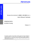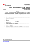
1
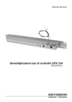
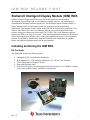
IDM RDK README FIRST Stellaris® Intelligent Display Module (IDM) RDK Stellaris reference design kits (RDKs) from Texas Instruments accelerate product development by providing ready-to-run hardware, example software, and comprehensive documentation including hardware design files. The Intelligent Display Module (IDM) is a highly integrated QVGA touch-panel module for automation and instrumentation applications. The compact design is based on the LM3S6918 Stellaris microcontroller. A key feature of the IDM is the Power over Ethernet (PoE) power system that facilitates both network and power connections with a single CAT5 cable. The 10/100 Ethernet capability connects the IDM to an array of networks – from dedicated industrial networks to the internet. The example application includes source code for an embedded web server. Development of software for the IDM is simplified by using the StellarisWare® comprehensive graphics library and ARM development tools from our tools partners. Installing and Using the IDM RDK Kit Contents The IDM RDK includes the following items: • • • • • Intelligent QVGA Touch Panel with Ethernet Wall adapter 24Vdc 15W with plug adapters for US, UK, EU, and Australia JTAG debug adapter (20-pin to 10-pin) Retractable Ethernet cable Reference Design Kit CD containing this Quickstart Guide, a User’s Manual, example source code, graphics library, and hardware design files Rev. 1.4 1 IDM RDK README FIRST Quickstart Application The IDM RDK comes preprogrammed with a quickstart application. Once you have powered the board, this application runs automatically. The application provides a security keypad to allow access to a door. The relay output is momentarily toggled upon entry of the access code to activate an electric door strike, unlocking the door. A demonstration of the Stellaris Graphics Library is also included within the application. Upon startup, the screen is blank and the hint at the bottom says to touch the screen. Press the screen to bring up the keypad, which is randomized as an added security measure. The current access code is provided in the hint at the bottom of the screen. Enter the access code and then press the ‘#’ key to end the code entry. If the correct access code is entered, the relay output toggles momentarily, as indicated by the hint at the bottom of the screen, and the screen goes blank. Touch the screen again to repeat the process. If an incorrect access code is entered, the screen goes blank and waits for another access attempt. A simple web server is provided to allow the access code to be changed. After booting, the software attempts to contact a DHCP server to allocate an IP address. If this does not succeed, a link local address of the form 169.254.xx.xx is allocated using the AUTOIP protocol as defined in RFC3927. Once an IP address is assigned, it is displayed at the bottom of the screen allowing the user to connect to the IDM's web server using a standard browser. The web page shows the current access code and provides a form for updating the access code. If a micro-SD card is present, the access code is stored in a file called “key.txt” in the root directory. This file is written whenever the access code is changed, and is read at startup to initialize the access code. If a micro-SD card is not present or the “key.txt” file does not exist, the access code defaults to 6918. Running the Quickstart Application Follow these steps to start running the quickstart application preprogrammed into the IDM. If a Power over Ethernet hub or switch is available, network and power connections to the IDM require only a single CAT5 cable connection. The IDM has been tested with a D-Link DES-1008PA 8-port switch, but any IEEE802.3af-compliant hub or switch will work. If a PoE hub or switch is not available, use the wall adapter included in the kit as follows: 1. Select the appropriate plug adapter to apply power (the RDK includes plugs for most countries) and slide it into the wall adapter. If necessary, the adapter can be removed by pressing the release latch. 2. Plug the DC plug into the power socket on the IDM. 3. Connect the wall adapter to a standard AC electrical outlet (115 V or 230 V). Rev. 1.4 2 IDM RDK README FIRST Using the Touch Panel 1. Touch the screen and the keypad appears. 2. Enter the access code provided in the hint at the bottom of the screen followed by the ‘#’ key. 3. The hint at the bottom of the screen indicates that the relay output has been toggling unlocking the door. Using the Web Server 1. Connect the Ethernet cable provided in the kit to the IDM. 2. Connect the other end of the Ethernet cable directly to your PC or LAN. 3. Power cycle the board by removing the plug and reinserting it into the power socket of the IDM. 4. The IDM attempts to locate a DHCP server when the board is first powered up. If the board is connected to a LAN and there is a DHCP server present, the board attempts to obtain an IP address from the DHCP server. If an IP address is obtained, then it will be displayed on the screen and you can move on to step 6. After a short period of time, if no DHCP server is found, the IDM uses the AUTOIP protocol to pick a link local IP address of the form 169.254.xx.xx. If you have connected the IDM to a LAN but an IP address could not be obtained from a DHCP server, it is recommended to go back to step 2 and connect the IDM directly to your PC. 5. If you have connected the IDM directly to your PC, your machine automatically detects the correct IP address and subnet settings after several seconds. In some cases, you need to manually configure your PC’s IP address and subnet mask. To do this, disable the machine’s wireless network connection and any other internet connections that could interfere with the network being created. Select the Internet Protocol (TCP/IP) connection within the Local Area Connection Properties and click on Properties. Next, manually configure your IP address to 169.254.19.60 and your subnet mask to 255.255.0.0, as shown below. Rev. 1.4 3 IDM RDK README FIRST The integrated PHY on the LM3S6918 has an Auto-MDX feature which allows you to use a straight-through or cross-over Ethernet cable. 6. To access the board’s web page, simply type the IP address into the address bar of your host’s web browser and the web page loads from the IDM. For example, if the default IP address, 169.254.19.60, is used, type http://169.254.19.60 into the web browser’s address bar. 7. Type a new four digit access code into the appropriate box of the web page and click Submit. 8. The access code has now been changed. The new access code can be tested by touching the screen to bring up the keypad and entering the new code followed by the ‘#’ key. Accessing the Graphics Demonstration 1. Touch the screen and the keypad appears. 2. Press the “*” key twice. The display changes to show an introduction to the demonstration. Rev. 1.4 4 IDM RDK README FIRST 3. Navigate through the various panels in the demonstration by pressing the “+” and “_” buttons at the bottom of the screen. 4. Exit back to the numeric keypad by pressing the “X” button found on the first and last demonstration panels. StellarisWare® A full set of C-based peripheral drivers is provided, covering all peripherals and functionality of the Stellaris devices. The StellarisWare package includes various example applications with project files for all major tool vendors that support Stellaris. Installing StellarisWare 1. Insert the RDK Documentation and Software CD into the CD-ROM drive of your computer. If Autoplay is enabled on your PC, the index.htm file automatically opens in your default web browser. If not, use Windows Explorer or other browser to open the index.htm file manually. 2. From the CD menu, select the Software button. Click the ‘Install’ link for StellarisWare. If you prefer to manually install StellarisWare from a zip file, the zip file is located in the “\Software\StellarisWare” directory. 3. To view the StellarisWare documentation, navigate to the installation directory and click the StellarisWare Peripheral Driver Library User’s Guide PDF file. IDM Example Applications StellarisWare includes several example applications for the IDM. If you installed StellarisWare to the default installation path of C:\StellarisWare, you can find the example applications for the IDM in “C:\StellarisWare\boards\rdk-idm”. Graphics Library StellarisWare includes a graphics library which can be used for the IDM. If you installed StellarisWare to the default installation path C:\ StellarisWare, you can find the graphics library in “C:\ StellarisWare\grlib”. LM Flash Programmer Utility This Windows application may be used to flash application or boot loader images to the IDM board either via Ethernet or using another Stellaris evaluation kit board as a USB-toJTAG/SWD adapter. It can be installed from the RDK-IDM CD and launched from the shortcut found in Start/All Programs/Luminary Micro/LM Flash Programmer. Rev. 1.4 5 IDM RDK README FIRST Conclusion You have now successfully operated the Intelligent Display Module (IDM) using the touch panel and web server. From here we recommend reading the Intelligent Display Module (IDM) Reference Design Kit User’s Manual, which explains how to use the IDM in more detail. Once you have completed that step, you will be prepared to start adapting the software and hardware for a specific application. References The following references are included on the IDM RDK documentation CD and are also available for download at www.luminarymicro.com: Intelligent Display Module (IDM) Reference Design Kit User’s Manual, publication number RDK-IDM-UM Intelligent Display Module (IDM) Motor RDK Software Reference Manual, publication number RDK-IDM-srm StellarisWare Graphics Library User’s Guide, publication number SW-GRL-UG Copyright © 2008–2009 Texas Instruments, Inc. All rights reserved. Stellaris and StellarisWare are registered trademarks of Texas Instruments. ARM and Thumb are registered trademarks, and Cortex is a trademark of ARM Limited. Other names and brands may be claimed as the property of others. Texas Instruments 108 Wild Basin Rd., Suite 350 Austin, TX 78746 Main: +1-512-279-8800 Fax: +1-512-279-8879 http://www.luminarymicro.com Rev. 1.4 12/8/2009 IMPORTANT NOTICE Texas Instruments Incorporated and its subsidiaries (TI) reserve the right to make corrections, modifications, enhancements, improvements, and other changes to its products and services at any time and to discontinue any product or service without notice. Customers should obtain the latest relevant information before placing orders and should verify that such information is current and complete. All products are sold subject to TI’s terms and conditions of sale supplied at the time of order acknowledgment. TI warrants performance of its hardware products to the specifications applicable at the time of sale in accordance with TI’s standard warranty. Testing and other quality control techniques are used to the extent TI deems necessary to support this warranty. Except where mandated by government requirements, testing of all parameters of each product is not necessarily performed. TI assumes no liability for applications assistance or customer product design. Customers are responsible for their products and applications using TI components. To minimize the risks associated with customer products and applications, customers should provide adequate design and operating safeguards. TI does not warrant or represent that any license, either express or implied, is granted under any TI patent right, copyright, mask work right, or other TI intellectual property right relating to any combination, machine, or process in which TI products or services are used. Information published by TI regarding third-party products or services does not constitute a license from TI to use such products or services or a warranty or endorsement thereof. Use of such information may require a license from a third party under the patents or other intellectual property of the third party, or a license from TI under the patents or other intellectual property of TI. Reproduction of TI information in TI data books or data sheets is permissible only if reproduction is without alteration and is accompanied by all associated warranties, conditions, limitations, and notices. Reproduction of this information with alteration is an unfair and deceptive business practice. TI is not responsible or liable for such altered documentation. Information of third parties may be subject to additional restrictions. Resale of TI products or services with statements different from or beyond the parameters stated by TI for that product or service voids all express and any implied warranties for the associated TI product or service and is an unfair and deceptive business practice. TI is not responsible or liable for any such statements. TI products are not authorized for use in safety-critical applications (such as life support) where a failure of the TI product would reasonably be expected to cause severe personal injury or death, unless officers of the parties have executed an agreement specifically governing such use. Buyers represent that they have all necessary expertise in the safety and regulatory ramifications of their applications, and acknowledge and agree that they are solely responsible for all legal, regulatory and safety-related requirements concerning their products and any use of TI products in such safety-critical applications, notwithstanding any applications-related information or support that may be provided by TI. Further, Buyers must fully indemnify TI and its representatives against any damages arising out of the use of TI products in such safety-critical applications. TI products are neither designed nor intended for use in military/aerospace applications or environments unless the TI products are specifically designated by TI as military-grade or "enhanced plastic." Only products designated by TI as military-grade meet military specifications. Buyers acknowledge and agree that any such use of TI products which TI has not designated as military-grade is solely at the Buyer's risk, and that they are solely responsible for compliance with all legal and regulatory requirements in connection with such use. TI products are neither designed nor intended for use in automotive applications or environments unless the specific TI products are designated by TI as compliant with ISO/TS 16949 requirements. Buyers acknowledge and agree that, if they use any non-designated products in automotive applications, TI will not be responsible for any failure to meet such requirements. Following are URLs where you can obtain information on other Texas Instruments products and application solutions: Products Amplifiers Data Converters DLP® Products DSP Clocks and Timers Interface Logic Power Mgmt Microcontrollers RFID RF/IF and ZigBee® Solutions amplifier.ti.com dataconverter.ti.com www.dlp.com dsp.ti.com www.ti.com/clocks interface.ti.com logic.ti.com power.ti.com microcontroller.ti.com www.ti-rfid.com www.ti.com/lprf Applications Audio Automotive Broadband Digital Control Medical Military Optical Networking Security Telephony Video & Imaging Wireless www.ti.com/audio www.ti.com/automotive www.ti.com/broadband www.ti.com/digitalcontrol www.ti.com/medical www.ti.com/military www.ti.com/opticalnetwork www.ti.com/security www.ti.com/telephony www.ti.com/video www.ti.com/wireless Mailing Address: Texas Instruments, Post Office Box 655303, Dallas, Texas 75265 Copyright © 2009, Texas Instruments Incorporated