1
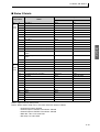
Overview
Com Data for
CompoWay/F
Digital Temperature Controllers
CompoWay/F
E5CN
E5CN
E5AN
E5AN
E5EN
E5EN
E5GN
E5GN
SYSWAY
Modbus
Com Data
for Modbus
Cat. No. H158-E1-02
Appendix
Communications Manual
Basic Type
Preface
Serial communications can be performed with the E5CN, E5AN, E5EN, and E5GN.
This manual describes the communications capabilities supported by the E5CN, E5AN, E5EN,
and E5GN. Read and understand this manual before using communications with the E5CN,
E5AN, E5EN, or E5GN and be sure you are performing communications correctly.
Keep this manual in a safe location where it will be available when needed.
For information on the communications functions of the Advanced Type E5CN-H, E5AN-H, and
E5EN-H Digital Temperature Controllers, refer to the Communications Manual provided for
Advanced Type models (Cat. No. H159).
© OMRON, 2008
All rights reserved. No part of this publication may be reproduced, stored in a retrieval system or transmitted, in
any form, or by any means, mechanical, electronic, photocopying, recording, or otherwise, without the prior written
permission of OMRON.
No patent liability is assumed with respect to the use of the information contained herein. Moreover, because
OMRON is constantly striving to improve its high-quality products, the information contained in this manual is
subject to change without notice. Every precaution has been taken in the preparation of this manual. Nevertheless,
OMRON assumes no responsibility for errors or omissions. Neither is any liability assumed for damages resulting
from the use of the information contained in this publication.
I
Read and Understand this Manual
Please read and understand this manual before using the products. Please consult your OMRON
representative if you have any questions or comments.
Warranty, Limitations of Liability
WARRANTY
OMRON's exclusive warranty is that the products are free from defects in materials and workmanship
for a period of one year (or other period if specified) from date of sale by OMRON.
OMRON MAKES NO WARRANTY OR REPRESENTATION, EXPRESS OR IMPLIED, REGARDING
NON-INFRINGEMENT, MERCHANTABILITY, OR FITNESS FOR PARTICULAR PURPOSE OF THE
PRODUCTS. ANY BUYER OR USER ACKNOWLEDGES THAT THE BUYER OR USER ALONE HAS
DETERMINED THAT THE PRODUCTS WILL SUITABLY MEET THE REQUIREMENTS OF THEIR
INTENDED USE. OMRON DISCLAIMS ALL OTHER WARRANTIES, EXPRESS OR IMPLIED.
LIMITATIONS OF LIABILITY
OMRON SHALL NOT BE RESPONSIBLE FOR SPECIAL, INDIRECT, OR CONSEQUENTIAL
DAMAGES, LOSS OF PROFITS OR COMMERCIAL LOSS IN ANY WAY CONNECTED WITH THE
PRODUCTS, WHETHER SUCH CLAIM IS BASED ON CONTRACT, WARRANTY, NEGLIGENCE, OR
STRICT LIABILITY.
In no event shall the responsibility of OMRON for any act exceed the individual price of the product on
which liability is asserted.
IN NO EVENT SHALL OMRON BE RESPONSIBLE FOR WARRANTY, REPAIR, OR OTHER CLAIMS
REGARDING THE PRODUCTS UNLESS OMRON'S ANALYSIS CONFIRMS THAT THE PRODUCTS
WERE PROPERLY HANDLED, STORED, INSTALLED, AND MAINTAINED AND NOT SUBJECT TO
CONTAMINATION, ABUSE, MISUSE, OR INAPPROPRIATE MODIFICATION OR REPAIR.
Application Considerations
SUITABILITY FOR USE
OMRON shall not be responsible for conformity with any standards, codes, or regulations that apply to
the combination of the products in the customer's application or use of the products.
At the customer's request, OMRON will provide applicable third party certification documents identifying
ratings and limitations of use that apply to the products. This information by itself is not sufficient for a
complete determination of the suitability of the products in combination with the end product, machine,
system, or other application or use.
The following are some examples of applications for which particular attention must be given. This is not
intended to be an exhaustive list of all possible uses of the products, nor is it intended to imply that the
uses listed may be suitable for the products:
• Outdoor use, uses involving potential chemical contamination or electrical interference, or conditions
or uses not described in this manual.
• Nuclear energy control systems, combustion systems, railroad systems, aviation systems, medical
equipment, amusement machines, vehicles, safety equipment, and installations subject to separate
industry or government regulations.
• Systems, machines, and equipment that could present a risk to life or property.
Please know and observe all prohibitions of use applicable to the products.
NEVER USE THE PRODUCTS FOR AN APPLICATION INVOLVING SERIOUS RISK TO LIFE OR
PROPERTY WITHOUT ENSURING THAT THE SYSTEM AS A WHOLE HAS BEEN DESIGNED TO
ADDRESS THE RISKS, AND THAT THE OMRON PRODUCTS ARE PROPERLY RATED AND
INSTALLED FOR THE INTENDED USE WITHIN THE OVERALL EQUIPMENT OR SYSTEM.
PROGRAMMABLE PRODUCTS
OMRON shall not be responsible for the user's programming of a programmable product, or any
consequence thereof.
II
Disclaimers
CHANGE IN SPECIFICATIONS
Product specifications and accessories may be changed at any time based on improvements and other
reasons.
It is our practice to change model numbers when published ratings or features are changed, or when
significant construction changes are made. However, some specifications of the products may be
changed without any notice. When in doubt, special model numbers may be assigned to fix or establish
key specifications for your application on your request. Please consult with your OMRON representative
at any time to confirm actual specifications of purchased products.
DIMENSIONS AND WEIGHTS
Dimensions and weights are nominal and are not to be used for manufacturing purposes, even when
tolerances are shown.
PERFORMANCE DATA
Performance data given in this manual is provided as a guide for the user in determining suitability and
does not constitute a warranty. It may represent the result of OMRON's test conditions, and the users
must correlate it to actual application requirements. Actual performance is subject to the OMRON
Warranty and Limitations of Liability.
ERRORS AND OMISSIONS
The information in this manual has been carefully checked and is believed to be accurate; however, no
responsibility is assumed for clerical, typographical, or proofreading errors, or omissions.
III
Safety Precautions
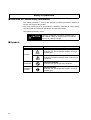
■ Definition of Precautionary Information
The following notation is used in this manual to provide precautions required to
ensure safe usage of the product.
The safety precautions that are provided are extremely important to safety. Always
read and heed the information provided in all safety precautions.
The following notation is used.
CAUTION
Indicates a potentially hazardous situation which, if
not avoided, is likely to result in minor or moderate
injury or in property damage.
■ Symbols
Symbol
Meaning
General Caution
Indicates non-specific general cautions, warnings,
and dangers.
Caution
Electrical Shock Caution
Indicates possibility of electric shock under specific
conditions.
IV
Prohibition
General Prohibition
Indicates non-specific general prohibitions.
Mandatory
Caution
General Caution
Indicates non-specific general cautions, warnings,
and dangers.
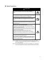
■ Safety Precautions
CAUTION
Do not touch the terminals while power is being supplied.
Doing so may occasionally result in minor injury due to electric
shock.
Do not allow pieces of metal, wire clippings, or fine metallic shavings or filings from installation to enter the product. Doing so may
occasionally result in electric shock, fire, or malfunction.
Do not use the product where subject to flammable or explosive
gas. Otherwise, minor injury from explosion may occasionally
occur.
Never disassemble, modify, or repair the product or touch any of
the internal parts. Minor electric shock, fire, or malfunction may
occasionally occur.
CAUTION - Risk of Fire and Electric Shock
a) This product is UL listed as Open Type Process Control
Equipment. It must be mounted in an enclosure that does not
allow fire to escape externally.
b) When using more than one shutoff switch, always turn OFF all
the shutoff switches to ensure that no power is being supplied
before servicing the product.
c) Signal inputs are SELV, limited energy. (See note 1.)
d) Caution: To reduce the risk of fire or electric shock, do not
interconnect the outputs of different Class 2 circuits. (See note
2.)
If the output relays are used past their life expectancy, contact
fusing or burning may occasionally occur.
Always consider the application conditions and use the output
relays within their rated load and electrical life expectancy. The life
expectancy of output relays varies considerably with the output
load and switching conditions.
Note 1: An SELV circuit is one separated from the power supply with double
insulation or reinforced insulation, that does not exceed 30 V r.m.s. and
42.4 V peak or 60 VDC.
Note 2: A class 2 power supply is one tested and certified by UL as having the
current and voltage of the secondary output restricted to specific levels.
V
CAUTION
Tighten the terminal screws to between 0.74 and 0.90 N·m. Loose
screws may occasionally result in fire. (See note 3.)
Set the parameters of the product so that they are suitable for the
system being controlled. If they are not suitable, unexpected
operation may occasionally result in property damage or
accidents.
A malfunction in the Temperature Controller may occasionally
make control operations impossible or prevent alarm outputs,
resulting in property damage. To maintain safety in the event of
malfunction of the Temperature Controller, take appropriate safety
measures, such as installing a monitoring device on a separate
line.
A semiconductor is used in the output section of long-life relays. If
excessive noise or surge is impressed on the output terminals, a
short-circuit failure is likely to occur. If the output remains shorted,
fire will occur due to overheating of the heater or other cause.
Take measures in the overall system to prevent excessive
temperature increase and to prevent fire from spreading.
When inserting the body of the Temperature Controller into the
case, confirm that the hooks on the top and bottom are securely
engaged with the case. If the body of the Temperature Controller
is not inserted properly, faulty contact in the terminal section or
reduced water resistance may occasionally result in fire or malfunction.
Note 3: The tightening torque is 0.5 N·m for the E5CN-U and 0.43 to 0.58 N·m for
the E5GN. The terminal torque is 0.5 to 0.6 N·m for auxiliary output 2 on
the E5GN.
VI
Precautions for Safe Use
Be sure to observe the following precautions to prevent operation failure, malfunction, or adverse affects
on the performance and functions of the product. Not doing so may occasionally result in unexpected
events. Use the product within specifications.
1) The product is designed for indoor use only. Do not use or store the product in any of the following
locations.
• Places directly subject to heat radiated from heating equipment.
• Places subject to splashing liquid or oil atmosphere.
• Places subject to direct sunlight.
• Places subject to dust or corrosive gas (in particular, sulfide gas and ammonia gas).
• Places subject to intense temperature change.
• Places subject to icing and condensation.
• Places subject to vibration and large shocks.
2) Use and store the Digital Temperature Controller within the rated ambient temperature and humidity.
Gang-mounting two or more temperature controllers, or mounting temperature controllers above each
other may cause heat to build up inside the temperature controllers, which will shorten their service
life. In such a case, use forced cooling by fans or other means of air ventilation to cool down the
Digital Temperature Controllers.
3) To allow heat to escape, do not block the area around the product. Do not block the ventilation holes
on the product.
4) Be sure to wire properly with correct polarity of terminals.
5) Use the specified size of crimp terminals for the E5CN, E5AN, or E5EN (M3.5, width of 7.2 mm or
less). For open-wired connections to the E5CN, E5AN, or E5EN, use stranded or solid copper wires
with a gauge of AWG24 to AWG14 (equal to a cross-sectional area of 0.205 to 2.081 mm 2). (The
stripping length is 5 to 6 mm.) Up to two wires of the same size and type or two crimp terminals can
be connected to one terminal. Do not connect more than two wires or more than two crimp terminals
to the same terminal.
Use the specified size of crimp terminals for the E5GN (M3.0, width of 5.8 mm or less). For openwired connections to the E5GN, use stranded or solid copper wires with a gauge of AWG24 to
6)
7)
AWG18 (equal to a cross-sectional area of 0.205 to 0.8231 mm2). (The stripping length for screw
terminals is 6 to 8 mm. The stripping length for screwless clamp terminals is 10 mm. The stripping
length for auxiliary output 2 is 6 mm.) Up to two wires of the same size and type or two crimp
terminals can be connected to one terminal. Do not connect more than two wires or more than two
crimp terminals to the same terminal.
Ferrules for screwless clamp terminals must be 0.8 to 1.4 mm in diameter and the exposed conductor
must be 8 to 12 mm in length. Ferrules for auxiliary output 2 must be 0.8 to 1.4 mm in diameter and
the exposed conductor must be 6 mm in length.
Do not wire the terminals which are not used.
To avoid inductive noise, keep the wiring for the Digital Temperature Controller's terminal block away
from power cables carry high voltages or large currents. Also, do not wire power lines together with or
parallel to Digital Temperature Controller wiring. Using shielded cables and using separate conduits or
ducts is recommended.
Attach a surge suppressor or noise filter to peripheral devices that generate noise (in particular,
motors, transformers, solenoids, magnetic coils or other equipment that have an inductance
component).
When a noise filter is used at the power supply, first check the voltage or current, and attach the noise
filter as close as possible to the temperature controller.
VII
8)
9)
10)
11)
12)
13)
14)
15)
16)
17)
18)
19)
20)
21)
22)
23)
24)
VIII
Allow as much space as possible between the Digital Temperature Controller and devices that
generate powerful high frequencies (high-frequency welders, high-frequency sewing machines, etc.)
or surge.
Use this product within the rated load and power supply.
Make sure that the rated voltage is attained within two seconds of turning ON the power using a
switch or relay contact. If the voltage is applied gradually, the power may not be reset or output
malfunctions may occur.
Make sure that the Temperature Controller has 30 minutes or more to warm up after turning ON the
power before starting actual control operations to ensure the correct temperature display.
When using self-tuning, turn ON power for the load (e.g., heater) at the same time as or before
supplying power to the Digital Temperature Controller. If power is turned ON for the Digital Temperature Controller before turning ON power for the load, self-tuning will not be performed properly and
optimum control will not be achieved.
A switch or circuit breaker should be provided close to this unit. The switch or circuit breaker should
be within easy reach of the operator, and must be marked as a disconnecting means for this unit.
Always turn OFF the power supply before pulling out the interior of the E5CN, E5AN, or E5EN, and
never touch nor apply shock to the terminals or electronic components. When inserting the interior of
the product, do not allow the electronic components to touch the case.
Always turn OFF the power supply before removing the terminal block from the E5GN, and never
touch nor apply shock to the terminals or electronic components.
Do not use paint thinner or similar chemical to clean with. Use standard grade alcohol.
Design system (control panel, etc) considering the 2 second of delay that the controller’s output to be
set after power ON.
The outputs may turn OFF when shifting to certain levels, such as the initial setting level. Take this
into consideration when performing control.
The number of EEPROM write operations is limited. Therefore, use RAM write mode when frequently
overwriting data during communications or others operations.
Always touch a grounded piece of metal before touching the Digital Temperature Controller to
discharge static electricity from your body.
Do not remove the terminal block from the E5CN, E5AN, or E5EN. Doing so may result in failure or
malfunction.
Control outputs that are voltage outputs are not isolated from the internal circuits. When using a
grounded thermocouple, do not connect any of the control output terminals to ground. (Doing so may
result in an unwanted circuit path, causing error in the measured temperature.)
When replacing the body of the E5CN, E5AN, or E5EN, check the condition of the terminals. If
corroded terminals are used, contact failure in the terminals may cause the temperature inside the
Digital Temperature Controller to increase, possibly resulting in fire. If the terminals are corroded,
replace the case as well.
When pulling out the terminal block of the E5GN to replace the Digital Temperature Controller, check
the condition of the terminals. If corroded terminals are used, contact failure in the terminals may
cause the temperature inside the Digital Temperature Controller to increase, possibly resulting in fire.
If the terminals are corroded, replace the terminal block as well.
Use suitable tools when taking the Digital Temperature Controller apart for disposal. Sharp parts
inside the Digital Temperature Controller may cause injury.
When applying Lloyd's standards, install the Digital Temperature Controller according to the requirements given in Shipping Standards in the E5CN, E5AN, E5EN, E5GN User’s Manual (Cat. No. H156).
Do not use the Temperature Controller if the front sheet is peeling or torn.
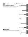
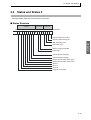
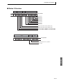
■ How This Manual is Organized
Overview
Conventions Used in This Manual
Overview
Descriptions in this manual are separated by the communications method.
Read the sections that are application to the system being used.
CompoWay/F
CompoWay/F
Communications Data
for CompoWay/F•SYSWAY
Com Data for
CompoWay/F
SYSWAY
SYSWAY
Modbus
Modbus
Com Data
for Modbus
Communications Data
for Modbus
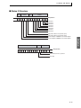
■ Related Manuals
Appendix
This manual describes the communications functions of the E5CN/AN/EN/GN.
For details on the functions of the E5CN/AN/EN/GN, refer to the User's Manual (H156).
Appendix
IX
X
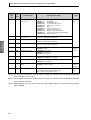
Table of Contents
Preface - - - - - - - - - - - - - - - - - - - - - - - - - - - - - - I
Conventions Used in This Manual - - - - - - - - - - -IX
SECTION 1
Communications Methods
1.1
Overview of Communications Methods ...................................................... 1-2
Introduction ......................................................................................... 1-2
Communications Specifications .......................................................... 1-3
Transmission Procedure ..................................................................... 1-3
Interface .............................................................................................. 1-4
Wiring .................................................................................................. 1-4
Communications Parameters .............................................................. 1-7
SECTION 2
CompoWay/F Communications Procedures
2.1
Data Format ............................................................................................... 2-2
2.2
Command Frame ................................................................................ 2-2
Response Frame ................................................................................ 2-3
Communications Data ......................................................................... 2-4
End Code Example ............................................................................. 2-4
Structure of Command Text ....................................................................... 2-6
2.3
PDU Structure ..................................................................................... 2-6
Area Definitions ................................................................................... 2-6
Type Code (Variable Type) ................................................................. 2-6
Addresses ........................................................................................... 2-7
Number of Elements ........................................................................... 2-7
List of Services (Main Request Codes and Sub-Request Codes) ...... 2-7
Detailed Description of the Services .......................................................... 2-9
2.4
Read Variable Area ............................................................................. 2-9
Write Variable Area ........................................................................... 2-10
Composite Read from Variable Area ................................................ 2-12
Composite Write to Variable Area ..................................................... 2-13
Read Controller Attributes ................................................................. 2-16
Read Controller Status ...................................................................... 2-17
Echoback Test .................................................................................. 2-18
Operation Command ......................................................................... 2-19
Response Code List ................................................................................. 2-26
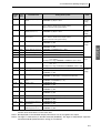
SECTION 3
Communications Data for CompoWay/F and SYSWAY
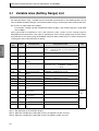
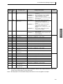
3.1
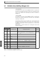
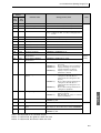
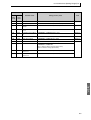
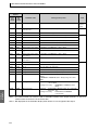
Variable Area (Setting Range) List ............................................................. 3-2
3.2
Status and Status 2 .................................................................................. 3-15
Status Structure ................................................................................ 3-15
Status 2 Structure ............................................................................. 3-17
Status Details .................................................................................... 3-18
Status 2 Details ................................................................................. 3-19
XI
SECTION 4
SYSWAY (E5@J and E5@X Format) Communications Procedures
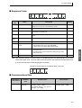
4.1
Data Format ............................................................................................... 4-2
4.2
Command Frame Format .................................................................... 4-2
Response Frame ................................................................................ 4-3
Communications Data ......................................................................... 4-3
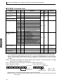
SYSWAY Command Lists ................................................................... 4-4
Command Descriptions .............................................................................. 4-5
Read Process Value ........................................................................... 4-5
Write Set Values ................................................................................. 4-6
Read Set Values and MV Monitor ....................................................... 4-7
Select Communications Writing .......................................................... 4-9
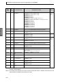
SECTION 5
Modbus Communications Procedure
5.1
Data Format ............................................................................................... 5-2
5.2
Command Frame ................................................................................ 5-2
Response Frame ................................................................................ 5-4
Error Codes ......................................................................................... 5-5
Function List ............................................................................................... 5-6
5.3
Variable Area .............................................................................................. 5-7
5.4
Detailed Description of the Services .......................................................... 5-9
Variable Read, Multiple ....................................................................... 5-9
Variable Write, Multiple ..................................................................... 5-11
Variable Write, Single/Operation Command ..................................... 5-14
Echoback Test .................................................................................. 5-20
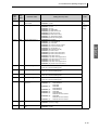
SECTION 6
Communications Data for Modbus
6.1
Variable Area (Setting Range) List ............................................................. 6-2
6.2
Status and status 2 .................................................................................. 6-17
Status Structure ................................................................................ 6-17
Status 2 Structure ............................................................................. 6-19
Status Details .................................................................................... 6-20
Status 2 Details ................................................................................. 6-21
Appendix
ASCII List .............................................................................................................A-2
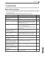
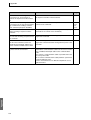
Troubleshooting ....................................................................................................A-3
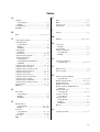
Index ..............................................................................................................................I-1
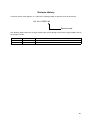
Revision History ........................................................................................................... R-1
XII
SECTION 1
Communications Methods
This section briefly describes the supported communications methods and
how to wire equipment. Refer to this section when setting up equipment.
1.1
Overview of Communications Methods ........................ 1-2
Introduction.............................................................. 1-2
Communications Specifications............................... 1-3
Transmission Procedure.......................................... 1-3
Interface................................................................... 1-4
Wiring ...................................................................... 1-4
RS-485 ..................................................... 1-4
RS-232C (E5AN, E5EN, and E5GN Only)1-6
Communications Parameters .................................. 1-7
Communications Parameter Setup .......... 1-7
Communications Parameters ................... 1-8
Setting Communications Writing .............. 1-9
1-1
SECTION 1 Communications Methods
Overview
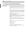
1.1 Overview of Communications Methods
■ Introduction
The program for the communications functions are created on the host
(personal computer, PLC, or other type of communications master), and
the E5CN/AN/EN/GN’s parameters are monitored or set from the host.
Therefore, the description provided here is from the viewpoint of the
host.
CompoWay/F is OMRON’s standard communications format for general
serial communications. This format uses a standard frame format as
well as the well-established FINS* commands used for OMRON’s
PLCs. Therefore, it can simplify communications between components
and the host.
*FINS (Factory Interface Network service)
The FINS protocol provides message communications between
controllers in OMRON FA networks.
Modbus is a standard communications control method that conforms to
the Modicon Company’s RTU-mode Modbus Protocol (PI-MBUS-300
Revision J).
Modbus is a registered trademark of Schneider Electric.
It supports functions equivalent to the CompoWay/F Read Variable
Area, Write Variable Area, Operation Command, and Echoback Test
functions.
The E5CN/AN/EN/GN suppor ts the following communications
functions.
• Reading/writing of parameters
• Operation instructions
• Selection of setup levels
Communications are subject to the following condition:
• Parameters can be written only when the Communications Writing
parameter is set to ON (enabled).
1-2
1.1 Overview of Communications Methods
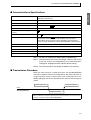
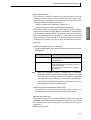
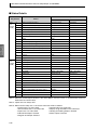
■ Communications Specifications
Overview
Transmission line connection
RS-485: Multidrop
RS-232C: Point-to-point
Communications method (See note 1.)
RS-485 (2-wire, half-duplex)/RS-232C
Synchronization method
Start-stop synchronization
Communications baud rate (See note 2.)
1,200, 2,400, 4,800, 9,600, 19,200, 38,400 or 57,600 bps
Communications code
ASCII
Communications data length (See notes
2 and 3.)
7 or 8 bits
Communications stop bits (See note 2.)
1 or 2 bits
Error detection
Vertical parity (none, even, or odd) (See note 2.)
FCS (Frame Check Sequence) with SYSWAY communications
BCC (Block Check Character) with CompoWay/F communications
CRC-16 (Cyclic Redundancy Check 16) with Modbus communications
Flow control
None
Interface
RS-485/RS-232C
Retry function
None
Communications buffer
217 bytes
Send data wait time
0 to 99 ms, default time: 20 ms
Note 1: RS-232C is supported by E5AN, E5EN, and E5GN only.
Note 2: Communications baud rate, data length, stop bits and vertical
parity can each be set independently in the communications
setting level. Highlighted values indicate default settings.
Note 3: The communications data length for Modbus must be 8 bits.
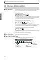
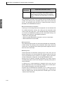
■ Transmission Procedure
When the host transmits a command frame, the E5CN/AN/EN/GN
transmits a response frame that corresponds to the command frame. A
single response frame is returned for each command frame. The
following diagram shows the operation of the command and response
frames.
Command frame
Command frame
Host
E5CN/AN/EN/GN
Response frame
Allow a wait time of at least 2 ms before the next command is sent after the host
receives a response from the E5CN/AN/EN/GN.
1-3
SECTION 1 Communications Methods
■ Interface
Overview
Communications with the host are carried out through a standard RS485 interface or RS-232C interface (E5AN, E5EN, and E5GN only).
Use a K3SC Interface Converter for RS-485 and RS-232C interface
conversion.
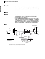
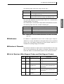
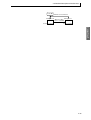
■ Wiring
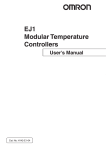
● RS-485
• The RS-485 connection can be either one-to-one or one-to-N. Up to 32
units including the host can be connected in a one-to-N system.
• The total cable length is 500 m max.
• Use a shielded, AWG24 to AWG14 (cross-sectional area of 0.205 to
2.081 mm2) twisted-pair cable for the E5CN, E5EN, or E5AN. Use a
shielded, AWG24 to AWG18 (cross-sectional area of 0.205 to
0.823 mm2) twisted-pair cable for the E5GN. The stripping length is 5 to
6 mm for the E5CN, E5AN, or E5EN, and 6 to 8 mm for the E5GN.
● E5CN
Communications
transceiver
Host
RS-485
E5CN
RS-485
Pin
12
11
Abbreviation
FG
−
+
SG
TX
Abbreviation
A (−)
B (+)
6.8 V
Shield
Terminator
120 Ω
(1/2 W)
A < B: "1" Mark
A > B: "0" Space
Shield
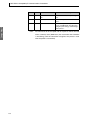
Specify both ends of the transmission path including the host
as the end node (that is, connect terminators to both ends).
Use a terminating resistance of at least 54 Ω.
1-4
E5CN
End node
RS-485
Abbreviation
Pin
12
A (−)
11
B (+)
Use a 120 Ω (1/2 W)
terminator.
RX
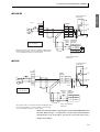
1.1 Overview of Communications Methods
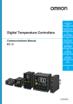
● E5AN/EN
Host
RS-485
E5AN/EN
RS-485
Abbreviation
TX
FG
Pin
Abbreviation
−
+
12
A (−)
B (+)
SG
22
11
RX
A (−)
B (+)
21
6.8 V
Shield
Terminator
120 Ω
(1/2 W)
A < B: "1" Mark
A > B: "0" Space
E5AN/EN
End node
RS-485
Pin
Abbreviation
12
A (−)
B (+)
11
Specify both ends of the transmission path including the host
as the end node (that is, connect terminators to both ends).
Use a terminating resistance of at least 54 Ω.
22
Shield
21
A (−)
B (+)
Use a 120 Ω (1/2 W)
terminator.
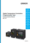
● E5GN
Communications
transceiver
Host
RS-485
E5GN
RS-485
Abbreviation
TX
FG
Pin
−
8
A (−)
+
7
B (+)
Abbreviation
RX
SG
6.8 V
A < B: "1" Mark
A > B: "0" Space
Shield
Terminator
120 Ω
(1/2 W)
E5GN
End node
RS-485
Pin
Shield
Specify both ends of the transmission path including the host
as the end node (that is, connect terminators to both ends).
Use a terminating resistance of at least 54 Ω.
Abbreviation
8
A (−)
7
B (+)
Use a 120 Ω (1/2 W)
terminator.
Match the communications specifications of the E5CN/AN/EN/GN and
the host. When using a 1: N connection, set the same communications
specifications in all of the Units. (Of course, each Unit must have a
unique unit number.)
1-5
Overview
Communications
transceiver
SECTION 1 Communications Methods
Overview
This section explains how to set the E5CN/AN/EN/GN’s communications specifications. For details on the host, refer to the User’s Manual
provided with the host.
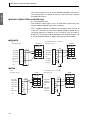
● RS-232C (E5AN, E5EN, and E5GN Only)
• A 1:1 connection is used.
• The maximum cable length is 15 m. To extend the transmission path,
use the OMRON Z3R RS-232C Optical Interface.
• Use a shielded, AWG24 to AWG14 (cross-sectional area of 0.205 to
2.081 mm2) twisted-pair cable for the E5CN, E5EN, or E5AN. Use a
shielded, AWG24 to AWG18 (cross-sectional area of 0.205 to
0.823 mm2) twisted-pair cable for the E5GN. The stripping length is 5 to
6 mm for the E5CN, E5AN, or E5EN, and 6 to 8 mm for the E5GN.
● E5AN/EN
Host
Host (IBM PC/AT or compatible)
E5AN/EN
RS-232C: 25-pin
E5AN/EN
RS-232C: 9-pin
RS-232C
RS-232C
SD (TXD)
2
No.
11
SD
RD (RXD)
2
No.
11
SD
RD (RXD)
3
12
RD
SD (TXD)
3
12
RD
RS (RTS)
4
SG
ER (DTR)
4
13
SG
CS (CTS)
5
SG
5
DR (DSR)
6
DR (DSR)
6
SG
7
RS (RTS)
7
20
CS(CTS)
8
ER (DTR)
13
1
FG
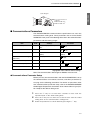
● E5GN
Host
Host (IBM PC/AT or compatible)
E5GN
RS-232C: 25-pin
RS-232C
RS-232C
SD
RD (RXD)
2
No.
7
SD
8
RD
SD (TXD)
3
8
RD
9
SG
ER (DTR)
4
9
SG
5
SG
5
DR (DSR)
6
DR (DSR)
6
SG
7
RS (RTS)
7
20
CS(CTS)
8
SD (TXD)
2
RD (RXD)
3
RS (RTS)
4
CS (CTS)
ER (DTR)
FG
1-6
E5GN
RS-232C: 9-pin
1
No.
7
1.1 Overview of Communications Methods
Cable Diagram
Overview
Cross-sectional area of
conductor
AWG24: 0.205 mm2
AWG14: 2.081 mm2
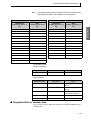
■ Communications Parameters
The E5CN/AN/EN/GN’s communications specifications are set in the
communications setting level. These parameters are set on the E5CN/
AN/EN/GN’s front panel. The following table shows the communications
parameters and their setting ranges.
Item
Code
Settings
Set Values
Communications protocol
psel
CompoWay/F (SYSWAY)/Modbus
cwf /mod
Communications unit number
u-no
0 to 99
0, 1 to 99
Communications baud rate
bps
1.2/2.4/4.8/9.6/19.2/38.4/57.6
(kbit/s)
1.2/2.4/4.8/ 9.6 /19.2/38.4/57.6
(kbit/s)
Communications data length
(See note.)
len
7/8 (bit)
7 /8 (bit)
Communications stop bits
sbit
1/2
1/ 2
Communications parity
prty
None, Even, Odd
none/ even /odd
Send data wait time
sdwt
0 to 99
0 to 99 ms, default time: 20 ms
Highlighted values indicate default settings.
Note: The communications data length for Modbus must be 8 bits.
● Communications Parameter Setup
Before you carry out communications with the E5CN/AN/EN/GN, set up
the communications unit number, baud rate, and other parameters by
carrying out the following procedure. For details on operations other
than communications parameter setup, refer to the E5CN/E5AN/E5EN/
E5GN Digital Temperature Controllers User's Manual Basic Type (Cat.
No. H156) for the devices being used.
1.
Press the O Key for at least three seconds to move from the
“operation level” to the “initial setting level.”
2.
Press the O Key for less than one second to move from the “initial
setting level” to the “communications setting level.”
3.
Select the parameters as shown below by pressing the M Key.
1-7
SECTION 1 Communications Methods
Overview
4.
Use the D or U Keys to change the parameter set values.
c
psel
Protocol Setting
cwf
c
u-no
Communications Unit
No.
1
c
bps
Communications
Baud Rate
9.6
c
len
Communications Data
Length (See note.)
7
c
56it
2
c
prty
Communications Stop
Bits (See note.)
Communications
Parity
eVen
c
sdwt
Note: Displayed only when the
Send Data Wait Time
20
Protocol Setting parameter is
set to CompoWay/F.
● Communications Parameters
When communications parameter settings have been changed, the new
settings must be enabled by resetting the Controller.
• Protocol Setting (psel)
The communications protocol can be selected. Set CompoWay/F
(SYSWAY) or Modbus.
• Communications Unit No. (u-no)
This parameter is for setting a unique unit number for each of the
Temperature Controllers. This unit number is set so that the host can
identify the Temperature Controller when communications are carried
out with the host. The unit number can be set to an integer value
between 0 and 99. The default is “1.” When two or more Temperature
Controllers are used, do not set the same unit number. Doing so will
prevent normal operation.
• Communications Baud Rate (bps)
This parameter is for setting the baud rate for communications with the
host. The communications baud rate settings are as follows: 1.2 (1200
bps), 2.4 (2400 bps), 4.8 (4800 bps), 9.6 (9600 bps), 19.2 (19200 bps),
38.4 (38400 bps) or 57.6 (57600 bps)
• Communications Data Length (len)
This parameter is for setting the number of communications data bits.
Set either “7 bits” or “8 bits.”
1-8
1.1 Overview of Communications Methods
• Communications Stop Bits (sbit)
Set either “1” or “2.”
• Communications Parity (prty)
The communications parity can be set. Set the parity to “none,” “even,”
or “odd.”
• Send Data Wait Time (sdwt)
The send data wait time is the delay from when the Controller receives
a command from the host computer until it returns a response. If the
response is returned too quickly, the host computer may not be able to
receive the response. Change the send data wait time as required. To
increase the response speed for communications, reduce the send data
wait time. The send data wait time can be set in 1-ms increments
between 0 and 99 ms. The default is 20 ms.
● Setting Communications Writing
Set the communications writing parameter to ON to allow the host to
write to the E5CN/AN/EN/GN via communications.
Parameter Setting
1.
Press the O Key for less than one second to move from the operation
level to the adjustment level.
2.
3.
Select the parameter as shown below by pressing the M Key.
Press the U or D Key to set the communications writing parameter
to ON.
c
l.adj
c
at
Adjustment Level
Display
Displayed only once when
entering adjustment level.
AT Execute/Cancel
off
c
cmwt
Communications
Writing
off
c
cmwt
on
•
•
•
•
1-9
Overview
This parameter is for setting the number of communications stop bits.
Overview
SECTION 1 Communications Methods
1-10
SECTION 2
CompoWay/F Communications Procedures
Read this section if you are to communicate using the CompoWay/F format.
2.1
2.2
2.3
2.4
Data Format.................................................................. 2-2
Command Frame................................................... 2-2
BCC Calculation Example ........................ 2-3
Response Frame ................................................... 2-3
Communications Data ........................................... 2-4
End Code Example................................................ 2-4
Structure of Command Text .......................................... 2-6
PDU Structure ....................................................... 2-6
Area Definitions ..................................................... 2-6
Type Code (Variable Type) ................................... 2-6
Addresses.............................................................. 2-7
Number of Elements.............................................. 2-7
List of Services (Main Request Codes and
Sub-Request Codes) ............................................. 2-7
Detailed Description of the Services............................. 2-9
Read Variable Area ............................................... 2-9
Write Variable Area ............................................. 2-10
Composite Read from Variable Area................... 2-12
Composite Write to Variable Area ....................... 2-13
Read Controller Attributes ................................... 2-16
Read Controller Status ........................................ 2-17
Echoback Test..................................................... 2-18
Operation Command ........................................... 2-19
Response Code List ................................................... 2-26
2-1
SECTION 2 CompoWay/F Communications Procedures
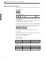
2.1 Data Format
Hexadecimal values are expressed by adding the prefix H’ before the number, e.g., H’02. Numbers
shown without the H’ prefix are ASCII characters.
CompoWay/F
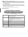
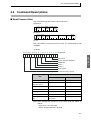
The number underneath each item in a frame indicates the number of bytes.
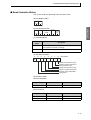
■ Command Frame
Text
Node number Sub-address SID
STX
1
0
2
0
2
BCC
Command text
0
1
BCC calculation range
ETX
1
1
STX
This code (H’02) indicates the beginning of the communications frame (text).
Always set this character in the first byte.
When STX is received again during reception, reception is carried out again from
the point where STX was received.
Node number
•
•
•
•
Sub-address
The sub-address is not used in the E5CN/AN/EN/GN. Be sure to set the subaddress to “00.”
SID (Service ID)
The service ID is not used in the E5CN/AN/EN/GN. Be sure to set the service ID to
“00.”
Command text
This is the command text area. For details, see 2.2 Structure of Command Text.
ETX
This code (H’03) indicates the end of the text.
BCC
This is the Block Check Character.
The BCC result is found by calculating the exclusive OR of the bytes from the node
number up to ETX.
2-2
This number specifies the transmission’s destination.
Specify the E5CN/AN/EN/GN’s communications unit number.
A BCD value between 00 and 99 or an ASCII value of XX can be set.
Specify “XX” for a broadcast transmission. No responses will be returned for
broadcast transmissions.
• No responses will be returned from node numbers other than the ones in the
above range.
2.1 Data Format
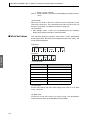
● BCC Calculation Example
The BCC (Block Check Character) is determined by calculating the
exclusive OR of the bytes from the node number up to ETX. The 8-bit
result is written to the BCC byte at the end of the frame.
STX
SID
Node number Sub-address
Command text
02H 0 (30H) 0 (30H) 0 (30H) 0 (30H) 0 (30H) 0 (30H)5 (35H) 0 (30H)3 (33H)
ETX
BCC
03H
35H
CompoWay/F
BCC = 30H+30H+30H+30H+30H+30H+35H+30H+33H+03H = 35H
The result of the calculation (35 hex) is written to the BCC byte.
The + symbols indicate XOR (exclusive OR) operations.
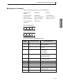
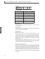
■ Response Frame
Node number
Sub-address
STX
1
End
code
0
2
End code
BCC
Command text
0
2
Name
ETX
2
1
1
Error
detection
priority
Description
00
Normal completion
The command ended normally without error.
None
0F
FINS command error
The specified FINS command could not be executed.
The FINS response code should indicate why the command
could not be executed.
8
10
Parity error
The sum total of bits whose received data is “1” does not
match the set value of the “communications parity” bit.
2
11
Framing error
Stop bit is “0.”
1
12
Overrun error
An attempt was made to transfer new data when the reception data buffer was already full.
3
13
BCC error
The calculated BCC value is different from the received
BCC value.
5
14
Format error
• The command text contains characters other than 0 to 9,
and A to F. This error does not apply to Echoback Tests.
(Refer to the Echoback Test for details.)
• There was no SID and command text. There was no command text.
• “MRC/SRC” not included in command text.
7
16
Sub-address error
• Illegal (unsupported) sub-address
• There was no sub-address, SID, and command text.
• Sub-address was less than two characters, and there was
no SID and command text
6
18
Frame length error
The received frame exceeds the specified (supported) number of bytes.
4
• An end code is returned for each command frame received that was addressed to the local node.
• No response will be returned unless the frame contained all elements up to the ETX and BCC.
• “Error Detection Priority” indicates the priority when two or more errors occur simultaneously.
2-3
SECTION 2 CompoWay/F Communications Procedures
CompoWay/F
■ Communications Data
Communications
format
Set (monitor)
values
CompoWay/F
8-digit hexadecimal
Negative values
Decimal point
2’s complement
Decimal point is removed and the result is converted
to hexadecimal.
Example conversion: 105.0 → 1050 → H’0000041A
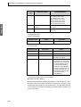
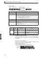
■ End Code Example
The following examples show the end code when a command did not
end normally.
Example 1) Illegal Sub-address, No SID, and No Command Text
Command
BCC
Node number Sub-address
STX
0
A
EXT
Response
BCC
Node number Sub-address End code
STX
0
A
1
6
EXT
End code is “16” (sub-address error).
The sub-address error code is used because the sub-address error has
a higher error detection priority than the format error.
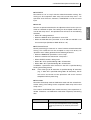
Example 2) No Command Text
Command
Node number Sub-address SID
STX
0
0
0
BCC
EXT
Response
BCC
Node number Sub-address End code
STX
0
0
1
4
The end code is “14” (format error).
Example 3) No Node Number Provided
Command
BCC
STX
EXT
The node number is lacking one character.
Response
There is no response.
2-4
EXT
2.1 Data Format
Example 4) No Sub-address and Illegal BCC
Command
BCC
Node number
STX
EXT
Err
Response
Node number Sub-address
0
0
1
3
EXT
CompoWay/F
STX
BCC
End code
The sub-address is “00” and the end code is “13” (BCC error).
2-5
SECTION 2 CompoWay/F Communications Procedures
2.2 Structure of Command Text
■ PDU Structure
An MRC (Main Request Code) and SRC (Sub-Request Code) followed
by the various required data is transferred to the command text.
CompoWay/F
Service Request PDU
MRC SRC
Data
The MRES (Main Response Code) and SRES (Sub-Response Code)
are transferred to the response frame following the above MRC/SRC.
Data is then transferred following the MRES and SRES.
Service Response PDU (Normal Response)
Data
MRC SRC MRES SRES
If the specified command text could not be executed, the service
response PDU will contain only the MRC/SRC and MRES/SRES.
Service Response PDU (Command Text Not Executed)
MRC SRC MRES SRES
MRES/SRES provides the response code. MRES/SRES are not output
when processing ends in a normal completion.
■ Area Definitions
Areas comprise only the variable area.
■ Type Code (Variable Type)
The following tables show the variable area type codes.
Variable type (1 byte)
MSB
LSB
0
Access size
11: Double word
10: Word
2-6
0
0
0
Area
0: Setup area 0
1: Setup area 1
Read/Write
0: Read only
1: Read/Write
2.2 Structure of Command Text
The following table summarizes setup areas 0 and 1.
Area
Description
Setup area 0
This area groups together the protect, manual control, operation, and adjustment levels.
Setup area 1
This area groups together the initial setting, communications
setting, advanced function setting, and calibration levels.
(Setting Range) List for details.
The variable type is converted to 2-byte ASCII and loaded to the frame.
The following table shows the available variable types.
Variable type
Description
C0/80
R/O (read only) parameter for setup area 0.
C1/81
R/W parameter for setup area 0.
C3/83
R/W parameter for setup area 1.
Note:
Setup area 1 has no read-only parameters, so there is no variable
type “C2.”
■ Addresses
An address is appended to each of the variable types. Express
addresses in 2-byte hexadecimal and append them for the specified
access size. The address depends on the parameter. Refer to 3.1
Variable Area (Setting Range) List for details.
■ Number of Elements
The number of elements is expressed in 2-byte hexadecimal. The range
that can be specified for the number of elements depends on the
command. Refer to 2.3 Detailed Description of the Services for details.
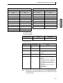
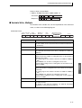
■ List of Services (Main Request Codes and Sub-Request Codes)
MRC
SRC
Name of service
Processing
01
01
Read Variable Area
This service reads from the variable
area.
01
02
Write Variable Area
This service writes to the variable
area.
01
04
Composite Read from
Variable Area
This service reads from the variable
area in the order specified by the
parameters.
01
13
Composite Write to
Variable Area
This service writes to the variable
area in the order specified by the
parameters.
05
03
Read Controller
Attributes
This service reads the model number and communications buffer size.
2-7
CompoWay/F
The type code depends on the parameter. Refer to 3.1 Variable Area
SECTION 2 CompoWay/F Communications Procedures
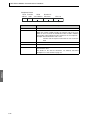
CompoWay/F
MRC
SRC
Name of service
Processing
06
01
Read Controller Status
This service reads the operating status.
08
01
Echoback Test
This service performs an echoback
test.
30
05
Operation Command
This service performs operations
such as RUN/STOP, executing/stopping AT (auto-tuning), and moving to
Setup Area 1.
Note:
No commands will be accepted and no responses will be returned
when a memory error (RAM error) has occurred or the Controller
is initializing (until the Controller recognizes the process value
after the power is turned ON).
2-8
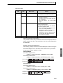
2.3 Detailed Description of the Services
2.3 Detailed Description of the Services
■ Read Variable Area
This service reads data from the variable area.
Service Request PDU
MRC SRC
Read
start address
2
4
0 1 0 1
2
2
Bit
position
Number of
elements
0 0
2
CompoWay/F
Variable
type
4
Service Request PDU
MRC SRC
0 1 0 1
2
2
Response
code
4
Read data (for number
of elements)
Number of elements
× 8 or 4
(1) Variable Type and Read Start Address
For details on variable types and read start addresses, see SECTION 3
Communications Data for CompoWay/F and SYSWAY.
(2) Bit Position
The E5CN/AN/EN/GN does not support bit access. Fixed to “00.”
(3) Number of Elements
Number of elements
Processing
0000
The read operation is not performed
(read data is not appended to the service response PDU), and processing
ends in “normal completion.”
Double word
(variable type C0,
C1, or C3)
0001 to 0019
(1 to 25)
Word (variable
type 80, 81, or 83)
0001 to 0032
(1 to 50)
The read operation is performed and
processing ends in a normal completion.
(4) Response Code
Normal Completion
Response code
0000
Name
Normal completion
Description
No errors were found.
Error Occurred
Response code
Error name
Cause
1001
Command too long
The command is too long.
1002
Command too short
The command is too short.
2-9
SECTION 2 CompoWay/F Communications Procedures
CompoWay/F
Response code
Error name
Cause
1101
Area type error
The variable type is wrong.
1103
Start address out-ofrange error
The read start address is out
of range.
110B
Response too long
The number of elements
exceeds the maximum.
1100
Parameter error
Bit position is not “00.”
2203
Operation error
EEPROM error
(5) Precautions
● Alarm Function
Even though alarms are not displayed on the Controller’s display, they
function normally in communications.
■ Write Variable Area
This service writes data to the variable area.
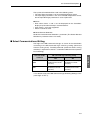
Service Request PDU
MRC SRC
0 1 0 2
2
2
Variable
type
Start
write address
2
4
Bit
position
0 0
2
Write Data (for
Number of
elements number of elements)
4
Number of elements
× 8 or 4
Service Response PDU
MRC SRC Response
code
0 1 0 2
2
2
4
(1) Variable Type and Write Start Address
For details on variable types and write start addresses, see SECTION 3
Communications Data for CompoWay/F and SYSWAY.
(2) Bit Position
The E5CN/AN/EN/GN does not support bit access. Fixed to “00.”
2-10
2.3 Detailed Description of the Services
(3) Number of Elements
Number of elements
Processing
0000
The write operation is not performed (do
not append write data to the service
request PDU) and processing ends in
“normal completion.”
0001 to 0018
(1 to 24)
Word (variable
type 80, 81, or 83)
0001 to 0030
(1 to 48)
The write operation is performed and
processing ends in a normal completion.
CompoWay/F
Double word
(variable type C0,
C1, or C3)
(4) Response Code
Normal Completion
Response code
0000
Name
Description
Normal completion
No errors were found.
Error Occurred
Response code
Error name
Cause
1002
Command too
short
The command is too short.
1101
Area type error
The variable type is wrong.
1103
Start address outof-range error
Write start address is out of range.
1104
End address outof-range error
The write end address (write start
address + number of elements)
exceeds the final address of the variable area.
1003
Number of elements/data mismatch
The number of data does not match
the number of elements.
1100
Parameter error
• Bit position is not “00.”
• The write data is out of the setting
range.
3003
Read-only error
Variable type “C0” was written to.
2203
Operation error
• The Communications Writing
parameter is set to “OFF” (disabled).
• Attempted to write to a parameter
in setup area 1 from setup area 0.
• Attempted to write to a protect
parameter from other than the protect level.
• AT (auto-tuning) was in progress.
(See note.)
• EEPROM error
2-11
SECTION 2 CompoWay/F Communications Procedures
Note:
For details on AT (auto-tuning), refer to the E5CN/E5AN/E5EN/
E5GN Digital Temperature Controllers User's Manual Basic Type
(Cat. No. H156).
(5) Precautions
● Alarm Function
CompoWay/F
Even though alarms are not displayed on the Controller’s display, they
function normally in communications.
■ Composite Read from Variable Area
This service reads in order the contents of specified addresses in the
variable area.
Service Request PDU
MRC SRC Variable
type
0 1 0 4
2
2
2
Read
address
4
Bit
position
0 0
2
Variable
type
Read
address
2
4
Bit
position
0 0
2
Service Response PDU
MRC SRC Response Variable
Read data
code
type
0 1 0 4
2
2
4
2 Number of elements ×8 or 4
Variable
type
2
Note:
Read data
Number of elements ×8 or 4
The read data is read together with the variable type in the order
specified by the command.
(1) Variable Type and Read Start Address
For details on variable types and read start addresses, see SECTION 3
Communications Data for CompoWay/F and SYSWAY.
(2) Bit Position
The E5CN/AN/EN/GN does not support bit access. Fixed to “00.”
(3) Number of Read Data Items (Variable Type + Read Data + Bit
Position Counted As 1 Item)
Read data length
2-12
Number of read data items
For double word (variable type C0, C1, or C3)
20 max.
For word (variable type 80, 81, or 83)
25 max.
2.3 Detailed Description of the Services
Note:
The following table gives the maximum number of read data items
when double-word data and word data are used together.
Composite Read
Composite Read
Word
(variable type 80, 81, or
83)
Double word
(variable type C0, C1, or
C3)
Word
(variable type 80, 81, or
83)
20
0
11
14
19
1
10
15
18
2
9
16
18
3
8
17
17
4
7
18
17
5
6
19
16
6
5
20
15
7
4
21
15
8
3
22
14
9
2
23
14
10
1
24
13
11
0
25
12
12
12
13
CompoWay/F
Double word
(variable type C0, C1, or
C3)
(4) Response Code
Normal Completion
Response code
0000
Name
Normal completion
Description
No errors were found.
Error Occurred
Response code
Error name
Cause
1002
Command too short
The command is too
short.
1101
Area type error
The variable type is
wrong.
110B
Response too long
The number of elements
exceeds the maximum.
1100
Parameter error
Bit position is not “00.”
2203
Operation error
EEPROM error
■ Composite Write to Variable Area
This service writes in order the contents of specified addresses to a
variable area.
2-13
SECTION 2 CompoWay/F Communications Procedures
Service Request PDU
CompoWay/F
MRC SRC Variable
type
0 1 1 3
2
2
2
Bit
Write
Write data
address position
0 0
4
2 Number of elements ×8 or 4
Variable
type
Write
address
2
4
Bit
Write data
position
0 0
2 Number of elements ×8 or 4
Service Response PDU
MRC SRC Response
code
0 1 1 3
2
2
4
(1) Variable Type and Write Start Address
For details on variable types and write start addresses, see SECTION 3
Communications Data for CompoWay/F and SYSWAY.
(2) Bit Position
The E5CN/AN/EN/GN does not support bit access. Fixed to “00.”
(3) Number of Write Data Items (Variable Type + Write Address + Bit
Position + Write Data Counted As 1 Item)
Write data length
Number of write data
items
For double word (variable type C0, C1, or C3)
12 max.
For word (variable type 80, 81, or 83)
17 max.
Note:
The following table gives the maximum number of write data
items when double-word data and word data are used together.
2-14
2.3 Detailed Description of the Services
Composite Write
Composite Write
Word
(variable type 80, 81, or
83 )
Double word
(variable type C0, C1, or
C3)
Word
(variable type 80, 81, or
83)
12
0
5
10
12
1
4
11
11
2
3
12
10
3
3
13
9
4
2
14
9
5
1
15
8
6
0
16
7
7
0
17
6
8
6
9
Name
Description
CompoWay/F
Double word
(variable type C0, C1, or
C3)
(4) Response Code
Normal Completion
Response code
0000
Normal completion
No errors were found.
Error Occurred
Response code
Error name
Cause
1002
Command too
short
The command is too short.
1101
Area type error
The variable type is wrong.
1100
Parameter error
• Bit position is not “00.”
• The write data is out of the setting
range.
3003
Read-only error
Variable type “C0” was written to.
2203
Operation error
• The Communications Writing
parameter is set to “OFF” (disabled).
• Attempted to write to a parameter
in setup area 1 from setup area 0.
• Attempted to write to a protect
parameter from other than the protect level.
• AT (auto-tuning) was in progress.
(See note.)
• EEPROM error
Note:
For details on AT (auto-tuning), refer to the E5CN/E5AN/E5EN/
E5GN Digital Temperature Controllers User's Manual Basic Type
(Cat. No. H156).
2-15
SECTION 2 CompoWay/F Communications Procedures
■ Read Controller Attributes
This service reads the model number and communications buffer size.
Service Request PDU
MRC SRC
CompoWay/F
0 5 0 3
2
2
Service Response PDU
MRC SRC
0 5 0 3
2
2
Response
code
Model No.
4
10
Buffer
size
0 0 D 9
4
(1) Model Number
The model number is expressed in 10-byte ASCII. When 10 bytes are
not required, pad the remaining bytes with spaces.
Example: The following model number is used for the E5CN-Q2HH03T
(voltage output, two auxiliary outputs, two heater burnout detection
inputs, communications functions, and TC/Pt universal input).
E 5 c n - Q 2 H H O
Note:
A lowercase “e” is applied to the E5AN/EN/GN (eg., e5an).
(2) Buffer Size
The communications buffer size is expressed in 2-byte hexadecimal,
and read after being converted to 4-byte ASCII.
Buffer size: 217 bytes (= H’00D9)
(3) Response Code
Normal Completion
Response code
0000
Name
Normal completion
Description
No errors were found.
Error Occurred
Response code
2-16
Name
Description
1001
Command too long
The command is too long.
2203
Operation error
EEPROM error
2.3 Detailed Description of the Services
■ Read Controller Status
This service reads the operating status and error status.
Service Request PDU
MRC SRC
0 6 0 1
2
2
CompoWay/F
Service Response PDU
MRC SRC
0 6 0 1
2
2
Response
code
Operating Related
status informa-
tion
4
2
2
(1) Operating Status
Operating
status
Description
00
Control is being carried out (error has not occurred in setup
area 0 and the Controller is running).
01
Control is not being carried out (state other than above).
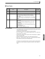
(2) Related Information
7
6
5
4
3
2
1
0
Bit position
0
Heater overcurrent (CT1)
Heater current hold (CT1)
AD converter error
Heater overcurrent (CT2)
Heater current hold (CT2)
Display range exceeded
Input error
(3) Response Code
Normal Completion
Response code
0000
Name
Normal completion
Description
No errors were found.
Error Occurred
Response code
Name
Description
1001
Command too long
The command is too long.
2203
Operation error
EEPROM error
2-17
SECTION 2 CompoWay/F Communications Procedures
■ Echoback Test
This service performs an echoback test.
CompoWay/F
Service Request PDU
MRC SRC
Test data
0 8 0 1
2
2
0 to 200
Service Response PDU
MRC SRC
0 8 0 1
2
2
Response
code
Test data
0 to 200
(1) Test Data
Set between 0 and 200 bytes of user-defined test data.
Set a value for the test data within the ranges shown below according to
the communications data length.
Communications
data length
Test Data
8 bits
ASCII data: H’20 to H’7E or H’A1 to H’FE
7 bits
ASCII data: H’20 to H’7E
Do not set the value H’40. No response will be returned.
(2) Response Code
Normal Completion
Response code
0000
Name
Normal completion
Description
No errors were found.
Error Occurred
Response code
2-18
Name
Description
1001
Command too long
The command is too long.
2203
Operation error
EEPROM error
2.3 Detailed Description of the Services
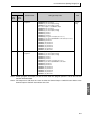
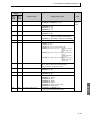
■ Operation Command
This service performs operations such as the following:
• RUN/STOP
• Multi-SP
• AT Execute/Cancel
• Write Mode
• Save RAM Data
• Software Reset
• Move to Setup Area 1
• Move to Protect Level
• Auto/Manual Switch
• Parameter Initialization
• Alarm Latch Cancel
• Invert Direct/Reverse
Operation
• Program Start
Service Request PDU
MRC SRC
3 0 0 5
2
2
Com- Related
mand informacode
tion
2
2
Service Response PDU
MRC SRC Response
code
3 0 0 5
2
2
4
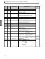
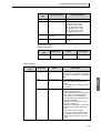
(1) Command Code and Related Information
Command
code
Command content
Related Information
00
Communications Writing
00: OFF (disabled)
01: ON (enabled)
01
RUN/STOP
00: Run
01: Stop
02
Multi-SP
00: Set point 0
01: Set point 1
02: Set point 2
03: Set point 3
03
AT Execute/Cancel
00: AT cancel
01: 100% AT execute
02: 40% AT execute
04
Write Mode
00: Backup mode
01: RAM write mode
05
Save RAM Data
00
06
Software Reset
00
07
Move to Setup Area 1
00
08
Move to Protect Level
00
09
Auto/Manual Switch
00: Automatic mode
01: Manual mode
0B
Parameter Initialization
00: Initialize to defaults
2-19
CompoWay/F
• Communications
Writing
SECTION 2 CompoWay/F Communications Procedures
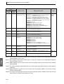
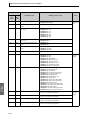
CompoWay/F
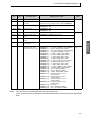
Command
code
Command content
Related Information
0C
Alarm Latch Cancel
00: Alarm 1 latch cancel
01: Alarm 2 latch cancel
02: Alarm 3 latch cancel
03: HB alarm latch cancel
04: HS alarm latch cancel
05: OC alarm latch cancel
0F: All alarm latch cancel
0E
Invert Direct/Reverse
Operation
00: Not invert
01: Invert
11
Program Start
00: Reset
01: Start
(2) Response Code
Normal Completion
Response code
0000
Name
Description
Normal completion
No errors were found.
Error Occurred
Response code
Error name
Cause
1001
Command too long
The command is too long.
1002
Command too short
The command is too short.
1100
Parameter error
Command code and related
information are wrong.
2203
Operation error
• The Communications Writing parameter is set to “OFF”
(disabled). The command is
received regardless of the
Communications Writing
parameter setting (ON/OFF).
• Processing could not be performed. For details, see (3)
Operation Commands and
Precautions below.
• EEPROM error
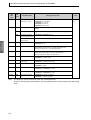
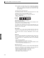
(3) Operation Commands and Precautions
● Communications Writing
Set the Communications Writing parameter to “ON: enabled” or “OFF:
disabled” with the related information setting. The setting can be
accepted in both setup area 0 and setup area 1. An operation error will
occur, however, if enabling or disabling communications writing is set
for an event input.
2-20
2.3 Detailed Description of the Services
● RUN/STOP
Set control to “run” or “stop” with the related information setting. The
setting can be accepted in both setup area 0 and setup area 1. An
operation error will occur, however, if RUN/STOP is set for an event
input.
● Multi-SP
switch to a desired set point. The setting can be accepted in both setup
area 0 and setup area 1. An operation error will occur in the following
situations.
• When AT is being executed.
• When the Multi-SP Uses parameter is set to OFF.
• When the Multi-SP Uses parameter is set to ON but multi-SP is set
for an event input (Number of Multi-SP Uses > 0).
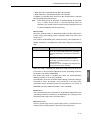
● AT Execute/Cancel
Set AT (auto-tuning) to “execute” or “cancel” with the related information
setting. This command can be accepted in setup area 0 only. An
“operation error” will be generated in the following instances:
• When the RUN/STOP parameter is set to “stop”
• When the command is executed in “setup area 1”
• When ON/OFF control is being used
• When 40% AT is specified during 100% AT execution.
• When 100% AT is specified during 40% AT execution.
In addition, a parameter error will occur if 40% AT is specified during
heating and cooling control.
Note:
If the same type of AT execution is specified during AT execution
(e.g., if 100% AT is specified during 100% AT execution), the AT
will not be restar ted and the operation will end in normal
completion with no processing.
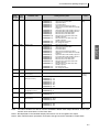
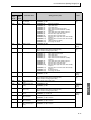
● Write Mode
Set either the backup mode or RAM write mode with the related information setting. The setting can be accepted in both setup area 0 and
setup area 1.
The number of EEPROM (non-volatile memory) write operations is
limited. Therefore, use RAM write mode when frequently overwriting
data.
Write mode
Backup mode
Description
The data is written to EEPROM when the parameters in the operation/adjustment levels (excluding
read-only parameters) are written by communications.
2-21
CompoWay/F
Set four set points beforehand in the adjustment level so that you can
SECTION 2 CompoWay/F Communications Procedures
Write mode
RAM write mode
Description
The data is not written to EEPROM when the parameters in the operation/adjustment levels (excluding
read-only parameters) are written by communications. Parameters can be changed by operating the
keys on the front panel of the controller.
• When the mode is switched from RAM write mode to backup mode, the
CompoWay/F
parameters in the operation/adjustment levels (excluding read-only
parameters) are written to EEPROM.
• The RAM write mode is enabled only when the Communications
Writing parameter is set to “ON” (enabled).
Consequently, when the Communications Writing parameter setting is
changed to “OFF” (disabled), the parameters in the operation/
adjustment levels (excluding read-only parameters) are written to
EEPROM even if the mode is set to RAM write mode.
● Save RAM Data
This command writes the parameters in the operation/adjustment levels
(excluding read-only parameters) to EEPROM. The setting can be
accepted in both setup area 0 and setup area 1.
● Software Reset
Restarts processing from the point when power is turned ON. The
setting can be accepted in both setup area 0 and setup area 1.
● Move to Setup Area 1
This command moves to “setup area 1” and can be accepted at both
setup areas 0 and 1. If the “initial setting/communications protect” is set
to “2,” an “operation error” will be generated, and the move to setup
area 1 will be prohibited.
When this move is carried out from setup area 0, the display indicates
the Input Type parameter in the “initial setting level.” When this
operation command is executed in setup area 1, the display will not
change.
● Move to Protect Level
This command moves to the “protect level” and can be accepted only in
setup area 0.When this command is issued in setup area 1, an
“operation error” will be generated, and the move to the protect level will
be prohibited.
◆ Moving to Protect Level in Manual Mode
When this operation command is issued in manual mode, an
“operation error” will be generated, and the move to the protect level
will be prohibited.
2-22
2.3 Detailed Description of the Services
● Auto/Manual Switch
This operation command switches the mode to manual mode or
automatic mode, based on the related information setting. This
command can be accepted in setup area 0 only. An “operation error”
will be generated in the following instances:
• When the command is executed in “setup area 1"
lated variable” will be displayed. When the Controller is switched from
manual mode to automatic mode, the operation level’s first parameter
will be displayed. When the Controller is switched to manual mode
while already in manual mode, the command will be completed
normally and the display will not change (the contents will not be
refreshed).
◆ Writing Auto/Manual Status in EEPROM
The write mode determines whether the auto/manual status is written
to EEPROM.
Write mode
Note:
Description
Backup mode
When the auto/manual mode is switched by
communications, the auto/manual status is written to EEPROM.
RAM write mode
When the auto/manual mode is switched by
communications, the auto/manual status is not
written to EEPROM.
The status can be written with the Controller
key operation.
When the auto/manual mode is switched with an operation
command through communications and the Controller is in RAM
write mode, the auto/manual status is not stored in EEPROM.
Consequently, if the Controller is restarted by performing a
software reset or turning the power OFF and ON again, the auto/
manual mode is set to the last saved status.
◆ Switching to Manual Mode during Auto-tuning
If the mode is switched during auto-tuning (AT), the AT will be
cancelled and the Controller will be switched to manual mode.
● Parameter Initialization
The present settings are returned to the default values and written to
EEPROM. This command can be accepted in setup area 1 only. When
this command is issued in setup area 0, an “operation error” will be
generated.
● Alarm Latch Cancel
2-23
CompoWay/F
• When auto/manual switching is disabled (not displayed)
When the Controller is switched to manual mode, the “manual manipu-
SECTION 2 CompoWay/F Communications Procedures
Related
information
00
Explanation (initialization values)
Default initialization values (See SECTION 3 Communications Data for CompoWay/F and SYSWAY for details.)
(These settings are the same as the ones used when
“FACT” is selected for the setting data’s set value initialization.)
CompoWay/F
The applicable alarm latch can be cleared with the related information
setting. The setting can be accepted in both setup area 0 and setup
area 1. An operation error will occur if communications writing is
disabled or if an EEPROM error occurs.
● Invert Direct/Reverse Operation
Inverting or not inverting direct/reverse operation can be selected with
the related information setting. The setting can be accepted in both
setup area 0 and setup area 1. The related information specifications
are written to EEPROM according to the write mode settings. An
operation error will occur in the following situations:
• When AT is being executed.
• When inverting direct/reverse operation is set for an event input.
• When executed in manual mode.
● Program Start
The simple program function can be reset/started with the related information setting. The setting can be accepted in both setup area 0 and
setup area 1. An operation error will be generated if program start has
been set in the event input.
● Setting Areas
Control operation is executed in setting area 0. In this state, you can
perform operations that are permitted only during control or those that
cause no problems even if control is in progress. These operations
include reading PVs, writing SPs, and change RUN/STOP status.
Setting area 0, however, prohibits operations that affect control,
including writing data at the initial setting level. (Reading setting data is
always allowed.)
In setting area 1, control operation is stopped. In this state, you can
perform operations that are not allowed in setting area 0. These operations include writing data at the initial setting level.
At power-ON, the Temperature Controller is set in setting area 0. To
move to setting area 1, use the “move-to-setting area 1” command. To
return to setting area 0, turn the power OFF and ON again, or use the
“software reset” command.
2-24
2.3 Detailed Description of the Services
Power ON
Software reset command
Setting area 0
Control in progress
“Move-to-setting
area 1” command
Setting area 1
Control stopped.
CompoWay/F
2-25
SECTION 2 CompoWay/F Communications Procedures
2.4 Response Code List
Normal Completion
CompoWay/F
Response
code
0000
Name
Normal completion
Error
detection
priority
Description
No errors were found.
None
Error Occurred
Response
code
Name
Error
detection
priority
Description
0401
Unsupported command
The service function for the relevant command is
not supported.
1
1001
Command too long
The command is too long.
2
1002
Command too short
The command is too short.
3
1101
Area type error
Wrong variable type
4
1103
Start address out-of-range error
The read/write start address is out of range.
5
1104
End address out-of-range error
The write end address (write start address +
number of elements) exceeds the final address
of the variable area.
6
1003
Number of elements/data mismatch
The amount of data does not match the number
of elements.
7
110B
Response too long
The response length exceeds the communications buffer size (when the number of elements
is greater than the maximum number of elements for that service).
8
1100
Parameter error
• Bit position is not “00.”
• The write data is out of the setting range.
• The command code or related information in
the operation command is wrong.
9
3003
Read-only error
Variable type “C0” was written to.
10
2203
Operation error
• The Communications Writing parameter is set
to “OFF” (disabled).
• Attempted to write to a parameter in setup
area 1 from setup area 0.
• Attempted to write to a protect parameter from
other than the protect level.
• Writing was carried out during AT execution.
• Processing is not possible by operation command.
• EEPROM error
11
2-26
SECTION 3
Communications Data for
CompoWay/F and SYSWAY
This section lists the details of the communications data in the
CompoWay/F and SYSWAY communications protocols.
3.1
3.2
Variable Area (Setting Range) List ............................... 3-2
Status and Status 2 .................................................... 3-15
Status Structure................................................... 3-15
Status 2 Structure................................................ 3-17
Status Details ...................................................... 3-18
Status 2 Details ................................................... 3-19
3-1
SECTION 3 Communications Data for CompoWay/F and SYSWAY
3.1 Variable Area (Setting Range) List
For communications using a variable type not enclosed in parentheses in the following table, the set
value is double-word data (8 digits). For communications using a variable type enclosed in parentheses,
the set value is single-word data (4 digits).
For example, variable type C0 is double-word data (8 digits), and variable type 80 is single-word
data (4 digits).
Items expressed in hexadecimal in the “Set (monitor) value” column are the setting range for
CompoWay/F communications. The values in parentheses are the actual setting range. Use the values
in parentheses as the setting range for SYSWAY communications. When there is a section reference for
a setting item, refer to that reference for details.
Com Data for
CompoWay/F
Variable
type
Address
Parameter name
Setting (monitor) value
Level
Operation
C0 (80)
0000
PV
Temperature: Use the specified range for each sensor.
Analog:
Scaling lower limit −5% FS to Scaling upper
limit +5% FS
C0 (80)
0001
Status (See notes 1 and 2.)
See 3.2 Status and Status 2 for details.
C0 (80)
0002
Internal Set Point (See note
1.)
SP lower limit to SP upper limit
C0 (80)
0003
Heater Current 1 Value
Monitor
H'00000000 to H'00000226 (0.0 to 55.0)
C0 (80)
0004
MV Monitor (Heating)
Standard: H'FFFFFFCE to H'0000041A (−5.0 to 105.0)
Heating and cooling:
H'00000000 to H'0000041A (0.0
to 105.0)
C0 (80)
0005
MV Monitor (Cooling)
H'00000000 to H'0000041A (0.0 to 105.0)
C0 (80)
0006
Heater Current 2 Value
Monitor
H'00000000 to H'00000226 (0.0 to 55.0)
C0 (80)
0007
Leakage Current 1 Monitor
H'00000000 to H'00000226 (0.0 to 55.0)
C0 (80)
0008
Leakage Current 2 Monitor
H'00000000 to H'00000226 (0.0 to 55.0)
C0 (80)
0009
Soak Time Remain
H'00000000 to H'0000270F (0 to 9999)
C0 (80)
000C
Multi-SP Monitor
H'00000000 to H'00000003 (0 to 3)
C0 (80)
000E
Decimal Point Monitor (See
note 1.)
H'00000000 to H'00000003 (0 to 3)
C0 (80)
000F
Control Output 1 ON/OFF
Count Monitor
H'00000000 to H'0000270F (0 to 9999)
C0 (80)
0010
Control Output 2 ON/OFF
Count Monitor
H'00000000 to H'0000270F (0 to 9999)
C0 (80)
0011
Status 2 (See notes 1 and
2.)
Refer to 3.2 Status and Status 2.
C0 (80)
0012
Status (See notes 1 and 3.)
Refer to 3.2 Status and Status 2.
C0 (80)
0013
Status 2 (See notes 1 and
3.)
Refer to 3.2 Status and Status 2.
Note 1: Not displayed on the Controller display.
Note 2: When the variable type is 80 (word access), the rightmost 16 bits are read.
Note 3: When the variable type is 80 (word access), the leftmost 16 bits are read.
3-2
Advanced
function
setting
Operation
3.1 Variable Area (Setting Range) List
Variable
type
C1 (81)
Address
0000
Parameter name
Operation/Adjustment Protect
Setting (monitor) value
H'00000000 (0):
H'00000001 (1):
H'00000002 (2):
H'00000003 (3):
C1 (81)
0001
Initial Setting/Communications Protect
H'00000000 (0):
H'00000001 (1):
H'00000002 (2):
0002
Setting Change Protect
H'00000000 (0):
H'00000001 (1):
Move to initial setting/communications
setting level is allowed. (Move to
advanced function setting level is displayed.)
Move to initial setting/communications
setting level is allowed. (Move to
advanced function setting level is not displayed.)
Move to initial setting/communications
setting level is prohibited.
OFF (Changing of setup on Controller display is allowed.)
ON (Changing of setup on Controller display is prohibited.)
C1 (81)
0003
Set Point
SP lower limit to SP upper limit
C1 (81)
0004
Alarm Value 1
H'FFFFF831 to H'0000270F (−1999 to 9999)
C1 (81)
0005
Alarm Value Upper Limit 1
H'FFFFF831 to H'0000270F (−1999 to 9999)
C1 (81)
0006
Alarm Value Lower Limit 1
H'FFFFF831 to H'0000270F (−1999 to 9999)
C1 (81)
0007
Alarm Value 2
H'FFFFF831 to H'0000270F (−1999 to 9999)
C1 (81)
0008
Alarm Value Upper Limit 2
H'FFFFF831 to H'0000270F (−1999 to 9999)
C1 (81)
0009
Alarm Value Lower Limit 2
H'FFFFF831 to H'0000270F (−1999 to 9999)
C1 (81)
000A
Alarm Value 3 (See note 1.)
H'FFFFF831 to H'0000270F (−1999 to 9999)
C1 (81)
000B
Alarm Value Upper Limit 3
(See note 1.)
H'FFFFF831 to H'0000270F (−1999 to 9999)
C1 (81)
000C
Alarm Value Lower Limit 3
(See note 1.)
H'FFFFF831 to H'0000270F (−1999 to 9999)
C1 (81)
000D
Heater Burnout Detection 1
H'00000000 to H'000001F4 (0.0 to 50.0)
C1 (81)
000E
SP 0
SP lower limit to SP upper limit
C1 (81)
000F
SP 1
SP lower limit to SP upper limit
C1 (81)
0010
SP 2
SP lower limit to SP upper limit
C1 (81)
0011
SP 3
SP lower limit to SP upper limit
C1 (81)
0012
Temperature Input Shift
H'FFFFF831 to H'0000270F (−199.9 to 999.9)
C1 (81)
0013
Upper Limit Temperature
Input Shift Value
H'FFFFF831 to H'0000270F (−199.9 to 999.9)
C1 (81)
0014
Lower Limit Temperature
Input Shift Value
H'FFFFF831 to H'0000270F (−199.9 to 999.9)
Note:
Protect
Operation
Adjustment
The alarm function can also be used in Controllers without alarm output terminals. In this case,
confirm alarm occurrences via the status data.
Note 1: Not displayed on the Controller display when Alarm 3 is not assigned to an output.
3-3
Com Data for
CompoWay/F
C1 (81)
No restrictions in operation and adjustment levels
Move to adjustment level is prohibited.
Display and change of only “PV” and
“PV/SP” parameters is allowed.
Display of only “PV” and “PV/SP” parameters is allowed.
Level
SECTION 3 Communications Data for CompoWay/F and SYSWAY
Com Data for
CompoWay/F
Variable
type
Address
Parameter name
Setting (monitor) value
Level
C1 (81)
0015
Proportional Band
H'00000001 to H'0000270F (0.1 to 999.9)
C1 (81)
0016
Integral Time
H'00000000 to H'00000F9F (0 to 3999)
C1 (81)
0017
Derivative Time
H’00000000 to H’00000F9F (0 to 3999)
(Range when RT is “OFF”)
H’00000000 to H’0000270F (0.0 to 999.9)
(Range when RT is “ON”)
C1 (81)
0018
Cooling Coefficient
H'00000001 to H'0000270F (0.01 to 99.99)
C1 (81)
0019
Dead Band
H'FFFFF831 to H'0000270F
(−199.9 to 999.9 for TC/Pt universal input models)
(−19.99 to 99.99 for Analog input models)
C1 (81)
001A
Manual Reset Value
H'00000000 to H'000003E8 (0.0 to 100.0)
C1 (81)
001B
Hysteresis (Heating)
H'00000001 to H'0000270F
(0.1 to 999.9 for TC/Pt universal input models)
(0.01 to 99.99 for Analog input models)
C1 (81)
001C
Hysteresis (Cooling)
H'00000001 to H'0000270F
(0.1 to 999.9 for TC/Pt universal input models)
(0.01 to 99.99 for Analog input models)
C1 (81)
001D
Heater Burnout Detection 2
H'00000000 to H'000001F4 (0.0 to 50.0)
C1 (81)
001E
HS Alarm 1
H'00000000 to H'000001F4 (0.0 to 50.0)
C1 (81)
001F
HS Alarm 2
H'00000000 to H'000001F4 (0.0 to 50.0)
C1 (81)
0020
Soak Time
H'00000001 to H'0000270F (1 to 9999)
C1 (81)
0021
Wait Band
H'00000000 (0): OFF
H'00000001 to H'0000270F
(0.1 to 999.9 for TC/Pt universal input models)
(0.01 to 99.99 for Analog input models)
C1 (81)
0022
MV at Stop
Standard: H'FFFFFFCE to H'0000041A (−5.0 to 105.0)
Heating and cooling:
H'FFFFFBE6 to H'0000041A
(−105.0 to 105.0)
C1 (81)
0023
MV at PV Error
Standard: H'FFFFFFCE to H'0000041A (−5.0 to 105.0)
Heating and cooling:
H'FFFFFBE6 to H'0000041A
(−105.0 to 105.0)
C1 (81)
0024
Manual MV
Standard: H'FFFFFFCE to H'0000041A (−5.0 to 105.0)
Heating and cooling:
H'FFFFFBE6 to H'0000041A (−105.0
to 105.0)
Manual
Control
C1 (81)
0025
SP Ramp Set Value
H'00000000 (0): OFF
H'00000001 to H'0000270F (1 to 9999)
Adjustment
C1 (81)
0026
MV Upper Limit
Standard: MV lower limit + 0.1 to H’0000041A (MV lower
limit + 0.1 to 105.0)
Heating and cooling:
H'00000000 to H'0000041A (0.0 to
105.0)
C1 (81)
0027
MV Lower Limit
Standard: H’FFFFFFCE to MV upper limit − 0.1 (−5.0 to MV
upper limit − 0.1)
Heating and cooling:
H'FFFFFBE6 to H'00000000 (−105.0
to 0.0)
3-4
Adjustment
3.1 Variable Area (Setting Range) List
Variable
type
Address
Parameter name
Setting (monitor) value
0028
Move to Protect Level
H'FFFFF831 to H'0000270F (−1999 to 9999)
C1 (81)
0029
Password to Move to Protect Level
H'FFFFF831 to H'0000270F (−1999 to 9999)
(Can only be set. The monitor value is always H’00000000.)
C1 (81)
002A
Parameter Mask Enable
H'00000000 (0): OFF
H'00000001 (1): ON
C1 (81)
002B
PF Key Protect
H'00000000 (0): OFF
H'00000001 (1): ON
C1 (81)
002C
MV Change Rate Limit
H'00000000 to H'000003E8 (0.0 to 100.0)
C1 (81)
002F
Heater Overcurrent Detection 1
H'00000000 to H'000001F4 (0.0 to 50.0)
C1 (81)
0030
Heater Overcurrent Detection 2
H'00000000 to H'000001F4 (0.0 to 50.0)
C1 (81)
0031
Extraction of Square Root
Low-cut Point
H'00000000 to H'000003E8 (0.0 to 100.0)
C3 (83)
0000
Input Type
(Controllers with TC/Pt
universal input) (See note.)
H'00000000 (0):
Pt (−200 to 850°C/−300 to 1500°F)
H'00000001 (1):
Pt (−199.9 to 500.0°C/−199.9 to 900.0°F)
H'00000002 (2):
Pt (0.0 to 100.0°C/0.0 to 210.0°F)
H'00000003 (3):
JPt (−199.9 to 500.0°C/−199.9 to 900.0°F)
H'00000004 (4):
JPt (0.0 to 100.0°C/0.0 to 210.0°F)
H'00000005 (5):
K (−200 to 1300°C/−300 to 2300°F)
H'00000006 (6):
K (−20.0 to 500.0°C/0.0 to 900.0°F)
H'00000007 (7):
J (−100 to 850°C/−100 to 1500°F)
H'00000008 (8):
J (−20.0 to 400.0°C/0.0 to 750.0°F)
H'00000009 (9):
T (−200 to 400°C/−300 to 700°F)
H'0000000A (10): T (−199.9 to 400.0°C/−199.9 to 700.0°F)
H'0000000B (11): E (−200 to 600°C/−300 to 1100°F)
H'0000000C (12): L (−100 to 850°C/−100 to 1500°F)
H'0000000D (13): U (−200 to 400°C/−300 to 700°F)
H'0000000E (14): U (−199.9 to 400.0°C/−199.9 to 700.0°F)
H'0000000F (15): N (−200 to 1300°C/−300 to 2300°F)
H'00000010 (16): R (0 to 1700°C/0 to 3000°F)
H'00000011 (17): S (0 to 1700°C/0 to 3000°F)
H'00000012 (18): B (100 to 1800°C/300 to 3200°F)
H'00000013 (19): Infrared temperature sensor
(K 140°F/60°C)
H'00000014 (20): Infrared temperature sensor
(K 240°F/120°C)
H'00000015 (21): Infrared temperature sensor
(K 280°F/140°C)
H'00000016 (22): Infrared temperature sensor
(K 440°F/220°C)
H'00000017 (23): 0 to 50 mV
H'00000018 (24): W (0 to 2300°C/0 to 3200°F)
H'00000019 (25): PL II (0 to 1300°C/0 to 2300°F)
Note:
Protect
Adjustment
Initial setting
The input type can be selected to match the connected sensor.
There are two input type specifications: Thermocouple/Resistance thermometer input and Analog
input.
3-5
Com Data for
CompoWay/F
C1 (81)
Level
SECTION 3 Communications Data for CompoWay/F and SYSWAY
Com Data for
CompoWay/F
Variable
type
Address
Parameter name
Setting (monitor) value
C3 (83)
0000
Input Type (analog input
models) (See note.)
H'00000000 (0): 4 to 20 mA
H'00000001 (1): 0 to 20 mA
H'00000002 (2): 1 to 5 V
H'00000003 (3): 0 to 5 V
H'00000004 (4): 0 to 10 V
C3 (83)
0001
Scaling Upper Limit
Scaling lower limit + 1 to H’0000270F (scaling lower limit + 1 to
9,999)
0002
Scaling Lower Limit
H’FFFFF831 to Scaling upper limit − 1 (−1999 to Scaling upper limit
− 1)
0003
Decimal Point (TC/Pt
universal input models)
H'00000000 to 00000001 (0 to 1)
Decimal Point (analog
input models)
H'00000000 to 00000003 (0 to 3)
C3 (83)
0004
Temperature Unit
H'00000000 (0): °C
H'00000001 (1): °F
C3 (83)
0005
SP Upper Limit
The range of values (without decimal point) is as follows:
Temperature: SP lower limit + 1 to Input range upper limit
Analog: SP lower limit + 1 to Scaling upper limit
C3 (83)
0006
SP Lower Limit
The range of values (without decimal point) is as follows:
Temperature: Input range lower limit to SP upper limit − 1
Analog: Scaling lower limit to SP upper limit − 1
C3 (83)
0007
PID ON/OFF
H'00000000 (0): ON/OFF
H'00000001 (1): 2 PID control
C3 (83)
0008
Standard or Heating/Cooling
H'00000000 (0): Standard
H'00000001 (1): Heating and cooling
C3 (83)
0009
ST
H'00000000 (0): OFF
H'00000001 (1): ON
C3 (83)
000A
Control Period (Heating)
H'00000000 (0): 0.5
H'00000001 to H'00000063 (1 to 99)
C3 (83)
000B
Control Period (Cooling)
H'00000000 (0): 0.5
H'00000001 to H'00000063 (1 to 99)
C3 (83)
000C
Direct/Reverse Operation
H'00000000 (0): Reverse operation
H'00000001 (1): Direct operation
Note:
Level
Initial setting
The input type can be selected to match the connected sensor.
There are two input type specifications: Thermocouple/Resistance thermometer input and Analog
input.
3-6
3.1 Variable Area (Setting Range) List
Variable type
Address
C3 (83)
000D
Parameter name
Alarm 1 Type
Setting (monitor) value
H'00000000 (0):
H'00000001 (1):
H'00000002 (2):
H'00000003 (3):
H'00000004 (4):
H'00000005 (5):
H'00000006 (6):
H'00000007 (7):
H'00000008 (8):
H'00000009 (9):
H'0000000A (10):
H'0000000B (11):
H'0000000C (12):
H'0000000D (13):
C3 (83)
000E
Alarm 2 Type
H'00000006 (6):
H'00000007 (7):
H'00000008 (8):
H'00000009 (9):
H'0000000A (10):
H'0000000B (11):
H'0000000C (12):
H'0000000D (13):
Alarm function OFF
Upper and lower-limit alarm
Upper-limit alarm
Lower-limit alarm
Upper and lower-limit range alarm
Upper and lower-limit alarm with standby
sequence
Upper-limit alarm with standby sequence
Lower-limit alarm with standby sequence
Absolute-value upper-limit alarm
Absolute-value lower-limit alarm
Absolute-value upper-limit alarm with
standby sequence
Absolute-value lower-limit alarm with
standby sequence
No alarm function
PV change rate alarm
C3 (83)
000F
Alarm 3 Type (See note 1.)
Same settings as the alarm 2 type
C3 (83)
0010
Communications Unit No.
(See note 2.)
H'00000000 to H'00000063 (0 to 99)
C3 (83)
0011
Communications Baud
Rate (See note 2.)
H'00000000 (0): 1.2
H'00000001 (1): 2.4
H'00000002 (2): 4.8
H'00000003 (3): 9.6
H'00000004 (4): 19.2
H'00000005 (5): 38.4
H'00000006 (6): 57.6
C3 (83)
0012
Communications Data
Length (See note 2.)
H'00000007 (7): 7
H'00000008 (8): 8
C3 (83)
0013
Communications Stop Bits
(See note 2.)
H'00000001 (1): 1
H'00000002 (2): 2
C3 (83)
0014
Communications Parity
(See note 2.)
H'00000000 (0): None
H'00000001 (1): Even
H'00000002 (2): Odd
C3 (83)
0015
Number of Multi-SP Uses
H'00000000 (0): No multi-SP
H'00000001 (1): 2SP
H'00000002 (2): 4SP
Note:
Initial setting
Com Data for
CompoWay/F
H'00000000 (0):
H'00000001 (1):
H'00000002 (2):
H'00000003 (3):
H'00000004 (4):
H'00000005 (5):
Alarm function OFF
Upper and lower-limit alarm
Upper-limit alarm
Lower-limit alarm
Upper and lower-limit range alarm
Upper and lower-limit alarm with standby
sequence
Upper-limit alarm with standby sequence
Lower-limit alarm with standby sequence
Absolute-value upper-limit alarm
Absolute-value lower-limit alarm
Absolute-value upper-limit alarm with
standby sequence
Absolute-value lower-limit alarm with
standby sequence
LBA (Loop Burnout Alarm)
PV change rate alarm
Level
Communications
setting
Initial setting
The alarm function can also be used in Controllers without alarm output terminals. In this case,
confirm alarm occurrences via the status data.
Note 1: Not displayed on the Controller display when Alarm 3 is not assigned to the output.
Note 2: After communications parameters have been changed, reset the Controller to enable them.
3-7
SECTION 3 Communications Data for CompoWay/F and SYSWAY
Com Data for
CompoWay/F
Variable
type
Address
Parameter name
Setting (monitor) value
None
RUN/STOP
Auto/manual switch
Program Start (See note 3.)
Direct/reverse operation
None
100% AT execute/cancel
40% AT execute/cancel
Setting change enable/disable
Communications writing enable/disable
Alarm latch cancel
Level
C3 (83)
0016
Event Input Assignment 1
(See note 1.)
H'00000000 (0):
H'00000001 (1):
H'00000002 (2):
H'00000003 (3):
H'00000004 (4):
H'00000005 (5):
H'00000006 (6):
H'00000007 (7):
H'00000008 (8):
H'00000009 (9):
H'0000000A (10):
C3 (83)
0017
Event Input Assignment 2
(See note 2.)
H'00000000 to H'0000000A (0 to 10)
* Same as for Event Input Assignment 1.
C3 (83)
0018
Event Input Assignment 3
H'00000000 to H'0000000A (0 to 10)
* Same as for Event Input Assignment 1.
C3 (83)
0019
Event Input Assignment 4
H'00000000 to H'0000000A (0 to 10)
* Same as for Event Input Assignment 1.
C3 (83)
001A
Multi-SP Uses
H'00000000 (0): OFF
H'00000001 (1): ON
C3 (83)
001B
SP Ramp Time Unit
H'00000000 (0): EU/second
H'00000001 (1): EU/minute
H'00000002 (2): EU/hour
C3 (83)
001C
SP Ramp Set Value
H'00000000 (0): OFF
H'00000001 to H'0000270F (1 to 9999)
C3 (83)
001D
Standby Sequence Reset
H'00000000 (0): Condition A
H'00000001 (1): Condition B
C3 (83)
001E
Auxiliary Output 1 Open in
Alarm
H'00000000 (0): Close in alarm
H'00000001 (1): Open in alarm
Advanced
function
setting
C3 (83)
001F
Alarm 1 Hysteresis
H'00000001 to H'0000270F
(0.1 to 999.9 for TC/Pt universal input models)
(0.01 to 99.99 for Analog input models)
Initial setting
Initial setting
Advanced
function
setting
Adjustment
Note 1: For Controllers with two event inputs (events 1 and 2), this cannot be set if the Number of Multi-SP
Uses parameter is set to 1 or 2.
Note 2: For Controllers with two event inputs (events 1 and 2), this cannot be set if the Number of Multi-SP
Uses parameter is set to 2.
Note 3: PRST (program start) can be set even when the program pattern is set to OFF, but the function
will be disabled.
3-8
3.1 Variable Area (Setting Range) List
Variable
type
Address
C3 (83)
0020
Auxiliary Output 2 Open in
Alarm
H'00000000 (0): Close in alarm
H'00000001 (1): Open in alarm
Advanced
function
setting
C3 (83)
0021
Alarm 2 Hysteresis
H'00000001 to H'0000270F
(0.1 to 999.9 for TC/Pt universal input models)
(0.01 to 99.99 for Analog input models)
Initial setting
C3 (83)
0022
Auxiliary Output 3 Open in
Alarm (See note 1.)
H'00000000 (0): Close in alarm
H'00000001 (1): Open in alarm
Advanced
function
setting
C3 (83)
0023
Alarm 3 Hysteresis
(See note 1.)
H'00000001 to H'0000270F
(0.1 to 999.9 for TC/Pt universal input models)
(0.01 to 99.99 for Analog input models)
Initial setting
C3 (83)
0024
HB ON/OFF
H'00000000 (0): OFF
H'00000001 (1): ON
C3 (83)
0025
Heater Burnout Latch
H'00000000 (0): OFF
H'00000001 (1): ON
Advanced
function
setting
C3 (83)
0026
Heater Burnout Hysteresis
H'00000001 to H'000001F4 (0.1 to 50.0)
C3 (83)
0027
ST Stable Range
H'00000001 to H'0000270F (0.1 to 999.9)
C3 (83)
0028
α
H'00000000 to H'00000064 (0.00 to 1.00)
C3 (83)
0029
MV Upper Limit
Standard: MV lower limit + 0.1 to H’0000041A (MV lower limit +
0.1 to 105.0)
Heating and cooling: H'00000000 to H'0000041A (0.0 to 105.0)
C3 (83)
002A
MV Lower Limit
Standard: H’FFFFFFCE to MV upper limit − 0.1 (−5.0 to MV upper
limit − 0.1)
Heating and cooling: H'FFFFFBE6 to H'00000000 (−105.0 to 0.0)
C3 (83)
002B
Input Digital Filter
H'00000000 to H'0000270F (0.0 to 999.9)
C3 (83)
002C
Additional PV Display
H'00000000 (0): OFF
H'00000001 (1): ON
C3 (83)
002D
MV Display
H'00000000 (0): OFF (display of manipulated variable OFF)
H'00000001 (1): ON (display of manipulated variable ON)
C3 (83)
002E
Automatic Display Return
Time
H'00000000 (0): OFF
H'00000001 to H'00000063 (1 to 99)
C3 (83)
002F
Alarm 1 Latch
H'00000000 (0): OFF
H'00000001 (1): ON
C3 (83)
0030
Alarm 2 Latch
H'00000000 (0): OFF
H'00000001 (1): ON
C3 (83)
0031
Alarm 3 Latch (See note 1.)
H'00000000 (0): OFF
H'00000001 (1): ON
C3 (83)
0032
Move to Protect Level Time
H'00000001 to H'0000001E (1 to 30)
C3 (83)
0033
Input Error Output
H'00000000 (0): OFF
H'00000001 (1): ON
C3 (83)
0034
Cold Junction Compensation Method
H'00000000 (0): OFF
H'00000001 (1): ON
C3 (83)
0035
MB Command Logic
Switching (See note 2.)
H'00000000 (0): OFF
H'00000001 (1): ON
Parameter name
Setting (monitor) value
Level
Com Data for
CompoWay/F
Adjustment
Advanced
function
setting
Note:
The alarm function can also be used in Controllers without alarm output terminals. In this case,
confirm alarm occurrences via the status data.
Note 1: Not displayed on the Controller display when Alarm 3 is not assigned to the output.
Note 2: The logic is switched only in the MB command (SYSWAY). The logic of CompoWay/F operation
command code 00 (communications writing) is not affected.
3-9
Com Data for
CompoWay/F
SECTION 3 Communications Data for CompoWay/F and SYSWAY
Variable type
Address
C3 (83)
0036
PV Change Color
H'00000000 (0): Orange
H'00000001 (1): Red
H'00000002 (2): Green
H'00000003 (3): Red to green: When ALM1 is ON
H'00000004 (4): Green to red: When ALM1 is ON
H'00000005 (5): Red to green to red: Within PV stable band: Green
Outside stable band: Red
H'00000006 (6): Green to orange to red: Within PV stable band: Orange
Outside stable band: Green, red
H'00000007 (7): Orange to green to red: Within PV stable band: Green
Outside stable band: Orange, red
C3 (83)
0037
PV Stable Band
H'00000001 to H'0000270F (0.1 to 999.9 for TC/Pt universal input
models) (0.01 to 99.99 for Analog input models)
C3 (83)
0038
Alarm 1 ON Delay
H'00000000 to H'000003E7 (0 to 999)
C3 (83)
0039
Alarm 2 ON Delay
H'00000000 to H'000003E7 (0 to 999)
C3 (83)
003A
Alarm 3 ON Delay
(See note 1.)
H'00000000 to H'000003E7 (0 to 999)
C3 (83)
003B
Alarm 1 OFF Delay
H'00000000 to H'000003E7 (0 to 999)
C3 (83)
003C
Alarm 2 OFF Delay
H'00000000 to H'000003E7 (0 to 999)
C3 (83)
003D
Alarm 3 OFF Delay
(See note 1.)
H'00000000 to H'000003E7 (0 to 999)
C3 (83)
003E
Transfer Output Type
H'00000000 (0): OFF
H'00000001 (1): Set point
H'00000002 (2): Set point during SP ramp
H'00000003 (3): PV
H'00000004 (4): MV monitor (heating)
H'00000005 (5): MV monitor (cooling)
C3 (83)
003F
Transfer Output
Upper Limit
H'FFFFF831 to H'0000270F (−1999 to 9999) (See note 2.)
C3 (83)
0040
Transfer Output
Lower Limit
H'FFFFF831 to H'0000270F (−1999 to 9999) (See note 2.)
C3 (83)
0041
Linear Current Output
H'00000000 (0): 4 to 20 mA
H'00000001 (1): 0 to 20 mA
C3 (83)
0042
Input Shift Type
H'00000000 (0): Temperature input 1-point shift
H'00000001 (1): Temperature input 2-point shift
C3 (83)
0043
MV at Stop and Error
Addition
H'00000000 (0): OFF
H'00000001 (1): ON
C3 (83)
0044
Auto/Manual Select
Addition
H'00000000 (0): OFF
H'00000001 (1): ON
C3 (83)
0045
RT
H'00000000 (0): OFF
H'00000001 (1): ON
C3 (83)
0046
HS Alarm Use
H'00000000 (0): OFF
H'00000001 (1): ON
C3 (83)
0047
HS Alarm Latch
H'00000000 (0): OFF
H'00000001 (1): ON
C3 (83)
0048
HS Alarm Hysteresis
H'00000001 to H'000001F4 (0.1 to 50.0)
C3 (83)
0049
LBA Detection Time
H'00000000 to H'0000270F (0 to 9999)
C3 (83)
004A
LBA Level
H'00000001 to H'0000270F (0.1 to 999.9 for TC/Pt universal input
models) (0.01 to 99.99 for Analog input models)
C3 (83)
004B
LBA Band
H'00000000 to H'0000270F (0.0 to 999.9 for TC/Pt universal input
models) (0.00 to 99.99 for Analog input models)
Parameter name
Setting (monitor) value
Level
Advanced
function
setting
Initial setting
Advanced
function
setting
Note 1: Not displayed on the Controller display when Alarm 3 is not assigned to the output.
Note 2: The setting (monitor) range depends on the transfer output type setting. (Refer to Section 5 Parameters in
the E5CN/E5AN/E5EN/E5GN Digital Temperature Controllers User's Manual Basic Type (Cat. No. H156).)
3-10
3.1 Variable Area (Setting Range) List
Variable
type
Address
Parameter name
Setting (monitor) value
004C
Protocol Setting (See
note 1.)
H'00000000 (0): CompoWay/F (SYSWAY)
H'00000001 (1): Modbus
C3 (83)
004D
Send Data Wait Time
(See note 1.)
H'00000000 to H'00000063 (0 to 99)
C3 (83)
004E
Control Output 1 Assignment
When control output 1 is a linear output:
H'00000000 (0): Not assigned.
H'00000001 (1): Control output (heating)
H'00000002 (2): Control output (cooling)
When control output 1 is an ON/OFF output:
H'00000000 (0): Not assigned.
H'00000001 (1): Control output (heating)
H'00000002 (2): Control output (cooling)
H'00000003 (3): Alarm 1
H'00000004 (4): Alarm 2
H'00000005 (5): Alarm 3
H'00000006 (6): Program end output (See note 2.)
H'00000007 (7): Control output ON/OFF count alarm (See note 3.)
H'00000008 (8): Work bit 1
H'00000009 (9): Work bit 2
H'0000000A (10): Work bit 3
H'0000000B (11): Work bit 4
H'0000000C (12): Work bit 5
H'0000000D (13): Work bit 6
H'0000000E (14): Work bit 7
H'0000000F (15): Work bit 8
C3 (83)
004F
Control Output 2 Assignment
H'00000000 (0): Not assigned.
H'00000001 (1): Control output (heating)
H'00000002 (2): Control output (cooling)
H'00000003 (3): Alarm 1
H'00000004 (4): Alarm 2
H'00000005 (5): Alarm 3
H'00000006 (6): Program end output (See note 2.)
H'00000007 (7): Control output ON/OFF count alarm (See note 3.)
H'00000008 (8): Work bit 1
H'00000009 (9): Work bit 2
H'0000000A (10): Work bit 3
H'0000000B (11): Work bit 4
H'0000000C (12): Work bit 5
H'0000000D (13): Work bit 6
H'0000000E (14): Work bit 7
H'0000000F (15): Work bit 8
Communications
setting
Advanced
function
setting
Com Data for
CompoWay/F
C3 (83)
Level
Note 1: After communications parameters have been changed, reset the Controller to enable them.
Note 2: P.END (program end output) can be set even when the program pattern is set to OFF, but the
function will be disabled.
Note 3: The output turns ON when the status of either the Control Output 1 ON/OFF Count Alarm or the
Control Output 2 ON/OFF Count Alarm turns ON.
3-11
SECTION 3 Communications Data for CompoWay/F and SYSWAY
Com Data for
CompoWay/F
Variable
type
Address
Parameter name
Setting (monitor) value
Level
C3 (83)
0050
Auxiliary Output 1
Assignment
H'00000000 (0): Not assigned.
H'00000001 (1): Control output (heating)
H'00000002 (2): Control output (cooling)
H'00000003 (3): Alarm 1
H'00000004 (4): Alarm 2
H'00000005 (5): Alarm 3
H'00000006 (6): Program end output (See note 1.)
H'00000007 (7): Control output ON/OFF count alarm (See note 2.)
H'00000008 (8): Work bit 1
H'00000009 (9): Work bit 2
H'0000000A (10): Work bit 3
H'0000000B (11): Work bit 4
H'0000000C (12): Work bit 5
H'0000000D (13): Work bit 6
H'0000000E (14): Work bit 7
H'0000000F (15): Work bit 8
C3 (83)
0051
Auxiliary Output 2
Assignment
H'00000000 to H'0000000F (0 to 15)
* Same as for the Auxiliary Output 1 Assignment parameter.
C3 (83)
0052
Character Select
H'00000000 (0): OFF
H'00000001 (1): ON
C3 (83)
0053
Program Pattern
H'00000000 (0): OFF
H'00000001 (1): STOP
H'00000002 (2): CONT
Initial setting
C3 (83)
0054
Soak Time Unit
H'00000000 (0): Minutes
H'00000001 (1): Hours
C3 (83)
0055
Alarm SP Selection
H'00000000 (0): Set point during SP ramp
H'00000001 (1): Set point
Advanced
function
setting
C3 (83)
0056
Auxiliary Output 3
Assignment
H'00000000 to H'0000000F (0 to 15)
* Same as for the Auxiliary Output 1 Assignment parameter.
C3 (83)
005B
Manual MV Limit Enable
H'00000000 (0): OFF
H'00000001 (1): ON
C3 (83)
005D
AT Calculated Gain
H'00000001 to H'00000064 (0.1 to 10.0)
C3 (83)
005E
AT Hysteresis
H'00000001 to H'0000270F (0.1 to 999.9: Controllers with TC/Pt
universal input)
(0.01 to 9.99: Controllers with analog input)
C3 (83)
005F
Limit Cycle MV Amplitude
H'00000032 to H'000001F4 (5.0 to 50.0)
C3 (83)
0067
PV Rate of Change Calculation Period
H'00000001 to H'000003E7 (1 to 999)
C3 (83)
0068
Automatic Cooling Coefficient Adjustment
H'00000000 (0): OFF
H'00000001 (1): ON
C3 (83)
0069
Heater Overcurrent Use
H'00000000 (0): OFF
H'00000001 (1): ON
C3 (83)
006A
Heater Overcurrent
Latch
H'00000000 (0): OFF
H'00000001 (1): ON
C3 (83)
006B
Heater Overcurrent Hysteresis
H'00000001 to H'000001F4 (0.1 to 50.0)
Advanced
function
setting
Note 1: P.END (program end output) can be set even when the program pattern is set to OFF, but the
function will be disabled.
Note 2: The output turns ON when the status of either the Control Output 1 ON/OFF Count Alarm or the
Control Output 2 ON/OFF Count Alarm turns ON.
3-12
3.1 Variable Area (Setting Range) List
Variable
type
Address
Parameter name
Setting (monitor) value
Level
006C
Extraction of Square
Root Enable
H'00000000 (0): OFF
H'00000001 (1): ON
Initial setting
C3 (83)
006D
PF Setting
H'00000000 (0): Not assigned.
H'00000001 (1): Run
H'00000002 (2): Stop
H'00000003 (3): RUN/STOP
H'00000004 (4): 100% AT execute
H'00000005 (5): 40% AT execute
H'00000006 (6): Alarm latch cancel
H'00000007 (7): Auto/manual switch
H'00000008 (8): Monitor/setting item
Advanced
function
setting
C3 (83)
006E
Monitor/Setting Item 1
H'00000000 (0): Disabled
H'00000001 (1): PV/SP/Multi-SP
H'00000002 (2): PV/SP/MV
H'00000003 (3): PV/SP/soak time remain
H'00000004 (4): Proportional band (P)
H'00000005 (5): Integral time (I)
H'00000006 (6): Derivative time (D)
H'00000007 (7): Alarm value 1
H'00000008 (8): Alarm value upper limit 1
H'00000009 (9): Alarm value lower limit 1
H'0000000A (10): Alarm value 2
H'0000000B (11): Alarm value upper limit 2
H'0000000C (12): Alarm value lower limit 2
H'0000000D (13): Alarm value 3
H'0000000E (14): Alarm value upper limit 3
H'0000000F (15): Alarm value lower limit 3
C3 (83)
006F
Monitor/Setting Item 2
H'00000000 to H'0000000F (0 to 15)
* Same as for Monitor/Setting Item 1.
C3 (83)
0070
Monitor/Setting Item 3
H'00000000 to H'0000000F (0 to 15)
* Same as for Monitor/Setting Item 1.
C3 (83)
0071
Monitor/Setting Item 4
H'00000000 to H'0000000F (0 to 15)
* Same as for Monitor/Setting Item 1.
C3 (83)
0072
Monitor/Setting Item 5
H'00000000 to H'0000000F (0 to 15)
* Same as for Monitor/Setting Item 1.
C3 (83)
0073
PV/SP Display Screen
Selection
H'00000000 (0):
H'00000001 (1):
H'00000002 (2):
H'00000003 (3):
H'00000004 (4):
H'00000005 (5):
H'00000006 (6):
H'00000007 (7):
Com Data for
CompoWay/F
C3 (83)
PV/SP
PV/SP/Multi-SP
PV/SP/MV
PV/SP/MV
PV/SP/Multi-SP
PV/SP/Multi-SP
PV/SP/MV
PV/SP/Multi-SP
PV/SP/Soak Time Remain
PV/SP/MV
PV/SP/Soak Time Remain
PV/SP/Soak Time Remain
C3 (83)
0074
MV Display Selection
H'00000000 (0): MV (heating)
H'00000001 (1): MV (cooling)
C3 (83)
0075
PV Decimal Point Display
H'00000000 (0): OFF
H'00000001 (1): ON
3-13
SECTION 3 Communications Data for CompoWay/F and SYSWAY
Com Data for
CompoWay/F
Variable
type
Address
Parameter name
Setting (monitor) value
C3 (83)
0076
PV Status Display Function
H'00000000 (0): OFF
H'00000001 (1): Manual
H'00000002 (2): Stop
H'00000003 (3): Alarm 1
H'00000004 (4): Alarm 2
H'00000005 (5): Alarm 3
H'00000006 (6): Alarm 1 to 3 OR status
H'00000007 (7): Heater alarm
C3 (83)
0077
SV Status Display Function
H'00000000 to H'00000006 (0 to 7)
* Same as for PV Status Display Function
C3 (83)
0078
Control Output 1
ON/OFF Count Alarm
Set Value
H'00000000 to H'0000270F (0 to 9999)
C3 (83)
0079
Control Output 2
ON/OFF Count Alarm
Set Value
H'00000000 to H'0000270F (0 to 9999)
C3 (83)
0083
Display Refresh Period
H'00000000 (0): OFF
H'00000001 (1): 0.25
H'00000002 (2): 0.5
H'00000003 (3): 1.0
3-14
Level
Advanced
function
setting
3.2 Status and Status 2
3.2 Status and Status 2
The figure below shows the structure of the status data.
■ Status Structure
Outputs
Input error
HB error
16 15 14 13 12 11 10 9 8 7 6 5 4 3 2 1 0 Bit position
0
0
Com Data for
CompoWay/F
Heater overcurrent (CT1)
Heater current hold (CT1)
A/D converter error
HS alarm (CT1)
Display range exceeded
Input error
Control output (heating)
Control output (cooling)
HB (heater burnout) alarm (CT1)
HB (heater burnout) alarm (CT2)
Alarm 1
Alarm 2
Alarm 3
Program end output
3-15
SECTION 3 Communications Data for CompoWay/F and SYSWAY
HB error
Operating status
Event inputs
31 30 29 28 27 26 25 24 23 22 21 20 19 18 17 16 15
Bit position
0
Event input 1
Event input 2
Event input 3
Event input 4
Write mode
Com Data for
CompoWay/F
EEPROM
Setup area
AT execute/cancel
RUN/STOP
Communications writing
Auto/manual switch
Program start
Heater overcurrent (CT2)
Heater current hold (CT2)
HS alarm (CT2)
3-16
3.2 Status and Status 2
■ Status 2 Structure
Spare
Outputs
Spare
16 15 14 13 12 11 10 9
0
0
Outputs
8
0
7
6
5
4
3
2
1
0
Bit position
0
Work bit 1
Work bit 2
Work bit 3
Work bit 4
Work bit 5
Work bit 6
Work bit 7
Work bit 8
Spare
Spare
Outputs
31 30 29 28 27 26 25 24 23 22 21 20 19 18 17 16 15
0
0
0
0
0
0
0
0
0
0
0
0
0
Bit position
0
Invert direct/reverse operation
SP ramp
3-17
Com Data for
CompoWay/F
OC (Heater Overcurrent) Alarm (CT1)
OC (Heater Overcurrent) Alarm (CT2)
Control Output 1 ON/OFF Count Alarm Output
Control Output 2 ON/OFF Count Alarm Output
SECTION 3 Communications Data for CompoWay/F and SYSWAY
■ Status Details
Bit Description
Bit position
Status
0
Com Data for
CompoWay/F
Status
(lower
word)
Status
(upper
word)
1
0
Heater overcurrent (CT1)
Not generated
Generated
1
Heater current hold (CT1) (See note 1.)
Update
Hold
2
A/D converter error
Not generated
Generated
3
HS alarm (CT1)
OFF
ON
4
Spare
OFF
---
5
Display range exceeded
Not generated
Generated
6
Input error
Not generated
Generated
7
Spare
OFF
---
8
Control output (heating)
OFF
ON
9
Control output (cooling)
OFF
ON
10
HB (heater burnout) alarm (CT1)
OFF
ON
11
HB (heater burnout) alarm (CT2)
OFF
ON
12
Alarm 1
OFF
ON
13
Alarm 2
OFF
ON
14
Alarm 3
OFF
ON
15
Program end output
OFF
ON
16
Event input 1
OFF
ON
17
Event input 2
OFF
ON
18
Event input 3
OFF
ON
19
Event input 4
OFF
ON
20
Write mode
Backup mode
RAM write mode
21
EEPROM
RAM = EEPROM
RAM ≠ EEPROM
22
Setup area
Setup area 0
Setup area 1
23
AT execute/cancel
AT canceled
AT execution in progress
24
RUN/STOP
Run
Stop
25
Communications writing
OFF (disabled)
ON (enabled)
26
Auto/manual switch
Automatic mode
Manual mode
27
Program start
Reset
Start
28
Heater overcurrent (CT2)
Not generated
Generated
29
Heater current hold (CT2) (See note 1.)
Update
Hold
30
Spare
OFF
---
31
HS alarm (CT2)
OFF
ON
Note 1: When the control output ON time is less than 100 ms, the bit is set to “1” and the heater current is
held at the last current value.
Note 2: “Spare” bits are always OFF.
Note 3: When read in setup area 1, the status of the bits will be as follows:
• Overcurrent: Last value held
• A/D converter error: Last value held
• Input error: Last value held
• HB and HS outputs: Cleared
• Program end output: Cleared
3-18
• Current hold: Last value held
• Display range exceeded: Last value held
• Heating and cooling outputs: Cleared
• Alarm outputs: Cleared
3.2 Status and Status 2
■ Status 2 Details
Bit Description
Bit position
Status
0
Status
(lower
word)
0
Work bit 1
OFF
ON
1
Work bit 2
OFF
ON
2
Work bit 3
OFF
ON
3
Work bit 4
OFF
ON
4
Work bit 5
OFF
ON
5
Work bit 6
OFF
ON
6
Work bit 7
OFF
ON
7
Work bit 8
OFF
ON
8
Spare
OFF
---
9
Spare
OFF
---
10
OC (Heater Overcurrent) Alarm (CT1)
OFF
ON
11
OC (Heater Overcurrent) Alarm (CT2)
OFF
ON
12
Control Output 1 ON/OFF Count Alarm
Output
OFF
ON
13
Control Output 2 ON/OFF Count Alarm
Output
OFF
ON
14
Spare
OFF
15
Spare
OFF
Com Data for
CompoWay/F
Status
(upper
word)
1
---
16
Spare
OFF
---
17
Spare
OFF
---
18
Spare
OFF
---
19
Spare
OFF
---
20
Invert direct/reverse operation
Not invert
Invert
21
SP ramp
OFF
During SP ramp
22
Spare
OFF
---
23
Spare
OFF
---
24
Spare
OFF
---
25
Spare
OFF
---
26
Spare
OFF
---
27
Spare
OFF
---
28
Spare
OFF
---
29
Spare
OFF
---
30
Spare
OFF
---
31
Spare
OFF
---
Note 1: “Spare” bits are always OFF.
Note 2: When read in setup area 1, the status of the bits will be as follows:
• Overcurrent Output: Cleared
• Control Output 1 ON/OFF Count Alarm: Cleared
• Control Output 2 ON/OFF Count Alarm: Cleared
• Work bits 1 to 8: Last value held
• SP ramp: Last value held
3-19
Com Data for
CompoWay/F
SECTION 3 Communications Data for CompoWay/F and SYSWAY
3-20
SECTION 4
SYSWAY (E5@J and E5@X
Format) Communications
Procedures
These communications procedures are supported to provide compatibility
with the E5@J and E5@X Digital Temperature Controllers. When using a
new system, we recommend using CompoWay/F communications.
4.1
4.2
Data Format.................................................................. 4-2
Command Frame Format ...................................... 4-2
FCS Calculation Example ........................ 4-2
Response Frame ................................................... 4-3
Communications Data ........................................... 4-3
SYSWAY Command Lists ..................................... 4-4
Command Descriptions ................................................ 4-5
Read Process Value.............................................. 4-5
Write Set Values.................................................... 4-6
Read Set Values and MV Monitor ......................... 4-7
Select Communications Writing............................. 4-9
4-1
SECTION 4 SYSWAY (E5@J and E5@X Format) Communications Procedures
4.1 Data Format
■ Command Frame Format
@
Communi- Header
cations
unit num- code
ber
Data
code
FCS
Text
Terminator
* CR
SYSWAY
FCS calculation range
@
The @ character (ASCII H’40) indicates the start of block format.
Communications
unit number
A number within the range 0 to 99 can be set in BCD. No response will be returned to a
node with a number outside of this range.
Header code
This is a 2-character alphabetic code that indicates the command type.
Data code
Set “02” only when reading and writing alarm value 2. Otherwise, set “01.”
Text
This area contains read values, write values, or status data. The data depends on the
command.
FCS
This is the Frame Check Sequence.
The FCS (Frame Check Sequence) is calculated by taking the exclusive OR of all characters from the @ character to the last text character and converting the result to ASCII
characters.
Terminator
Indicates the end of the block format.
The terminator is composed of “*” and CR (Carriage Return = H’0D).
● FCS Calculation Example
The FCS (Frame Check Sequence) is calculated by taking the exclusive
OR of all characters from the @ character to the last text character and
converting that 8-bit result into two ASCII characters.
Start
Communication
character
unit number
Header
code
Data code
FCS
@(40H) 0 (30H) 0 (30H) R (52H) X (58H) 0 (30H) 1 (31H) 4 (34H) B (42H)
FCS = 4 0 H +3 0 H +3 0 H +5 2 H +5 8 H + 3 0 H + 3 1 H = 4 B H
The calculation result (4B hex) is converted to ASCII and written to the FCS bytes.
4 → 34H
B → 42H
The + symbols indicate XOR (exclusive OR) operations.
4-2
4.1 Data Format
■ Response Frame
@
End
code
Communi- Header
cations
unit num- code
ber
End
code
Name
FCS
Text
Terminator
* CR
Description
Priority
Parity error
The sum total of bits whose received data is “1” does not
match the set value of “communications parity.”
1
11
Framing error
Stop bit is “0.”
2
12
Overrun error
An attempt was made to transfer new data when the reception
data buffer was already full.
3
13
FCS error
The calculated FCS value is different from the received FCS
value.
4
IC (See
note.)
Undefined error
The header code of the command cannot be interpreted.
5
14
Format error
The command length is incorrect.
6
0D
Non-executable command
• The set value was written when the Communications Writing parameter was set to “OFF” (disabled).
• The set value was written during AT execution.
7
15
Undefined data value
• The write data is either outside the setting range or not a
numerical value.
• The data code is either outside the setting range or not a
numerical value.
8
00
Normal completion
The command ended normally without error.
---
Note: The response format is unusual when an “Undefined error” has occurred due to an invalid
command header code. The error code will be contained in the response’s header code rather
than the end code. See the following diagram for details.
Response Format when an “Undefined Error” Occurred
@
Communi- Header
cations
unit num- code
ber
I
C
FCS
Terminator
* CR
■ Communications Data
Communications Format
SYSWAY
Setting
(monitor)
value
Four digits
(decimal)
Negative values
If the leftmost digit is “−1,” it is set to “A.”
Example: −1999 → A999
If the leftmost digit is “-,” it is set to “F.”
Example: −10 → F010
Decimal Point
The decimal point is removed.
Example: 105.0 → 1050
4-3
SYSWAY
10
SECTION 4 SYSWAY (E5@J and E5@X Format) Communications Procedures
■ SYSWAY Command Lists
Header
code
Data
code
Selecting Communications Writing
MB
01
Write mode selection
(See note 1.)
ME
01
Select backup mode
MA
01
Select RAM write mode
Save operation/
adjustment set value
MW
01
Save operation/adjustment set value
Writing set values
WS
01
Write set point
W%
01
Write alarm value 1
W%
02
Write alarm value 2
Category
SYSWAY
Read set value and
manipulated variable
monitor
Command
R/W
Select communications writing
WB
01
Write proportional band
WN
01
Write integral time
WV
01
Write derivative time
WI
01
Write temperature input shift values
WW
01
Write heater burnout detection
RS
01
Read set point
R%
01
Write alarm value 1
R%
02
Write alarm value 2
RB
01
Read proportional band
RN
01
Write integral time
RV
01
Write derivative time
RI
01
Write temperature input shift values
RW
01
Write heater burnout detection
RO
01
Read MV monitor
Read SP upper and
lower limit values
RL
01
Read SP upper and lower limit values
Read process value
RX
01
Read process value
Read the heater
current monitor
RZ
01
Heater current value monitor
Read the initial status
RU
01
Read the initial status
Data
length
Remarks
Write
4B
Write
None
Write
4B
Read
4B
Read
8B
Read both upper/
lower limit values at once
Read
8B
See note 2.
Read
8B
See note 3.
Read
5B
See note 4.
• No commands will be accepted and no responses will be returned when a memory error (RAM error)
has occurred or during initialization (until the process value is recognized after power is turned ON).
• When a write operation is performed while there is a memory error (EEPROM error), data will not be
written and the command will end with “normal completion.” Read operations will be executed
normally.
Note 1: The number of EEPROM (non-volatile memory) write operations is limited. Therefore, use RAM
write mode when frequently overwriting data.
Note 2: The process value read range is the same as the input’s display range.
Note 3: Status (last 4 bytes)
15 14 13 12 11 10 9 8 7 6 5 4 3 2 1 0 Bit position
0 0 0 0 0 0 0 0 0 0 0 0 0 0 0
Overflow
Display hold
Note 4. Status (first 2 bytes)
7 6 5 4 3 2 1 0 Bit position
0 0 0 0 0 0
Control
Output operation:
1
0
ON/OFF PID
Direct Reverse
• Overflow: Set 1 when the heater current value is greater than 55.0 A.
• Display hold: Set 1 when the control output ON time is less than 100 ms. The previous heater current
value is held.
4-4
4.2 Command Descriptions
4.2 Command Descriptions
■ Read Process Value
This command reads the process value and status.
Command
@
Communi- Header
cations
unit num- code
ber
Data FCS Terminator
code
R X 0 1
* CR
Response
@
Communi- Header
cations
unit num- code
ber
R X
End
code
PV
Status
FCS
Terminator
* CR
(1) PV
See SECTION 3 Communications Data for CompoWay/F and
SYSWAY.
(2) Status
15 14 13 12 11 10 9 8 7 6 5 4 3 2 1 0 Bit position
0 0
0
0
0 0 0 0
0 0
SYSWAY
Input error
Heater burnout detection
EEPROM
Alarm 1
Alarm 2
Write mode
Communications writing
Description
Item
0
1
Input error
Not generated
Generated
Heater burnout detection (See note 1.)
OFF or does not function
ON
EEPROM
RAM = EEPROM
RAM ≠ EEPROM
Alarm 1
OFF or does not function
ON
Alarm 2
OFF or does not function
ON
Write mode
Backup mode
RAM write mode
Communications writing
OFF (disabled) or does
not function
ON (enabled)
Note: When reading from setup area 1, the status of the bits will be as
follows:
• Input error: Last value held
• Heater burnout detection: Cleared
4-5
SECTION 4 SYSWAY (E5@J and E5@X Format) Communications Procedures
• Alarms 1 and 2: Cleared
Note 1. Heater burnout is the status corresponding to heater burnout 1
(CT1).
(3) End Code
When the end code is “00,” this indicates normal completion of the
command. Otherwise, the command could not be processed. For
details on end codes, see Response Frame on page 4-3.
(4) Precautions
• Even though alarms 1 and 2 are not displayed on the Controller
display, they function normally in communications.
■ Write Set Values
This command writes the set point, alarm values 1 and 2, proportional
band, integral time, derivative time, temperature input shift values, and
heater burnout detection.
Command
@
Communi- Header
cations
unit num- code
ber
Data
code
Write
value
FCS
Terminator
* CR
SYSWAY
Response
@
Communi- Header
cations
unit num- code
ber
End FCS
code
Terminator
* CR
(1) Header Code
Header code
Command
WS
Write set point
W%
Write alarm values 1 and 2
WB
Write proportional band
WN
Write integral time
WV
Write derivative time
WI
Write temperature input shift values
WW
Write heater burnout detection
(2) Data Code
Set the data code to “02” only when writing alarm value 2. In all other
cases, set to “01.”
(3) Write Value
For details on the write value (set value) range, see SECTION 3
Communications Data for CompoWay/F and SYSWAY.
4-6
4.2 Command Descriptions
(4) Precautions
● Alarm Values 1 and 2
When the alarm 1 type is set to “upper and lower-limit alarm,” “upper
and lower-limit range alarm,” or “upper and lower-limit alarm with
standby sequence,” the alarm’s upper and lower limits are set independently. The “alarm value 1" setting is disabled and the “alarm value
upper limit 1” and “alarm value lower limit 1” settings are used as the
alarm set values.
For this reason, when an “upper and lower-limit alarm” is set, write
values are written by communications to “alarm value upper limit 1” and
“alarm value lower limit 1” and not to “alarm value 1.” The same applies
to “alarm value 2.”
● Temperature Input Shift Value
When the 2-point shift method is used, the Temperature Input Shift is
disabled and the Upper Limit Temperature Input Shift Value and Lower
Limit Temperature Input Shift Value parameters are enabled as the
temperature input shift set values. For this reason, write values are
written to the Upper Limit Temperature Input Shift Value and Lower
Limit Temperature Input Shift Value parameters and not to the Temperature Input Shift parameter.
• The Input Type parameter is set to infrared temperature sensor.
• The Input Type parameter is not set to infrared temperature sensor,
but the Input Shift Type parameter is set to 2-point shift.
● Alarms
• Even when alarms 1 and 2 are not displayed on the Controller's
display, they function normally in communications.
• Only alarms 1 and 2 are supported.
• Alarm 3 cannot be used.
● Heater Burnout Detection
Written to “heater burnout detection 1.” (The value is not written to
“heater burnout 2 detection.”)
■ Read Set Values and MV Monitor
This command reads the set point, alarm values 1 and 2, proportional
band, integral time, derivative time, temperature input shift values,
heater burnout detection, and MV monitor.
Command
@
Communi- Header
cations
unit num- code
ber
Data FCS
code
Terminator
* CR
4-7
SYSWAY
The 2-point shift method will be used in the following cases:
SECTION 4 SYSWAY (E5@J and E5@X Format) Communications Procedures
Response
@
Communi- Header
cations
unit num- code
ber
End Read value FCS
code
Terminator
* CR
(1) Header Code
Header code
Command
RS
Read set point
R%
Read alarm values 1 and 2
RB
Read proportional band
RN
Read integral time
RV
Read derivative time
RI
Read temperature input shift values
RW
Read heater burnout detection
RO
Read MV monitor
(2) Data Code
Set the data code to “02” only when writing alarm value 2. In all other
cases, set to “01.”
(3) Read Value
SYSWAY
For details on the read value ranges, see SECTION 3 Communications
Data for CompoWay/F and SYSWAY.
(4) Precautions
● Alarm Values 1 and 2
When the alarm 1 type is set to “upper and lower-limit alarm,” “upper
and lower-limit range alarm,” or “upper and lower-limit alarm with
standby sequence,” the alarm’s upper and lower limits are set independently. The “alarm value 1” setting is disabled and the “alarm value
upper limit 1” and “alarm value lower limit 1” settings are used as the
alarm set values.
For this reason, when “upper/lower-limit alarm” is set, the value of
“alarm value upper limit 1” and not “alarm value 1” is the value read by
communications. The same applies to “alarm value 2.”
● Temperature Input Shift Value
When the 2-point shift method is used, the Temperature Input Shift
parameter is disabled and the Upper Limit Temperature Input Shift
Value and Lower Limit Temperature Input Shift Value parameters are
enabled as the temperature input shift set values. For this reason, when
2-point shift method is being used, the Upper Limit Temperature Input
Shift Value parameter is read and not the Temperature Input Shift
parameter.
4-8
4.2 Command Descriptions
The 2-point shift method will be used in the following cases:
• The Input Type parameter is set to infrared temperature sensor.
• The Input Type parameter is not set to infrared temperature sensor,
but the Input Shift Type parameter is set to 2-point shift.
● Alarm
• Even when alarms 1 and 2 are not displayed on the Controller's
display, they function normally in communications.
• Only alarms 1 and 2 are supported.
• Alarm 3 cannot be used.
● Heater Burnout Detection
Reads the Heater Burnout Detection 1 parameter. (The Heater Burnout
Detection 2 parameter value is not read.)
■ Select Communications Writing
The logic of the MB command changes as shown in the table below
according to the MB command logic switching setting (advanced
function setting level). The MB command (communications writing
selection) is equivalent to the E5@J Controller’s MB command (remote/
local switching).
MB command logic switching setting
OFF
ON
0000
Communications writing
enabled (remote mode
selection)
Communications writing
disabled (local mode
selection)
0001
Communications writing
disabled (local mode
selection)
Communications writing
enabled (remote mode
selection)
• The default value of the MB Command Logic Switching Setting is OFF
(same logic as E5@J).
4-9
SYSWAY
Text data of MB
command
SYSWAY
SECTION 4 SYSWAY (E5@J and E5@X Format) Communications Procedures
4-10
SECTION 5
Modbus Communications
Procedure
Read this section if you are to communicate using the Modbus format.
5.1
5.2
5.3
5.4
Data Format.................................................................. 5-2
Command Frame................................................... 5-2
CRC-16 Calculation Example................... 5-3
Response Frame ................................................... 5-4
Normal Response Frame ......................... 5-4
Error Response Frame............................. 5-4
Error Codes ........................................................... 5-5
No Response............................................ 5-5
Function List ................................................................. 5-6
Variable Area ................................................................ 5-7
Addresses ................................................ 5-7
Number of Elements................................. 5-8
Set Values ................................................ 5-8
Detailed Description of the Services............................. 5-9
Variable Read, Multiple ......................................... 5-9
Variable Write, Multiple........................................ 5-11
Variable Write, Single/Operation Command........ 5-14
Echoback Test..................................................... 5-20
5-1
SECTION 5 Modbus Communications Procedure
5.1 Data Format
The data format complies with the Modbus (RTU) communications
protocol, so commands from the host and responses from the E5CN/
AN/EN/GN are contained in data blocks called frames.
The structure of the command and response frames is described below.
In the following explanations, hexadecimal values are expressed by
adding the prefix H’ before the number, e.g., H’02. Numbers and alphabetic characters without the H’ prefix are ASCII characters.
■ Command Frame
When using RTU mode, start with a silent interval of at least 3.5
character times and end with a silent interval of at least 3.5 character
times.
Slave Function
address code
1
Data
CRC-16
1
2 bytes
CRC-16 calculation range
Modbus
Silent interval of 3.5 character times minimum.
Slave address
Specify the unit number.
The unit number can be set between H’00 to H’63 hexadecimal (0 to 99 decimal).
Specify H’00 for a broadcast transmission. No responses will
be returned for broadcast transmissions.
Function code
The function code is a 1-byte hexadecimal code that indicates
the type of command sent from the host device.
Data
This is the text data associated with the specified function
code. Specify the required data, such as the variable address
or setting data. (Set in hexadecimal.)
CRC-16
Cyclical Redundancy Check
This check code is calculated with the data from the slave
address to the end of the data.
The check code is 2-byte hexadecimal.
Silent interval of 3.5 character times minimum.
5-2
5.1 Data Format
● CRC-16 Calculation Example
Messages are processed one byte at a time in the work memory (a 16bit register known as the CRC register).
(1)The CRC register is initialized to H’FFFF.
(2)An XOR operation is performed on the content of the CRC register
and the first byte of the message, and the result is returned to the
CRC register.
(3)The MSB is packed with zeroes and the CRC register is shifted 1 bit
to the right.
(4)If the bit shifted from the LSB is 0, step 3 is repeated (next bit-shift
processing).
If the bit shifted from the LSB is 1, an XOR is performed on the
content of the CRC register and H’A001, and the result is returned to
the CRC register.
(5)Steps 3 and 4 are repeated until 8 bits are shifted.
(6)CRC processing continues to the end of the message, as XOR
operations are performed on the content of the CRC register and the
next byte of the message, step 3 is repeated, and the result is
returned to the CRC register.
(7)The result of the CRC calculation (value in the CRC register) is
appended to the last byte of the message.
Example of Appending the Calculation Result
When the calculated CRC value is H’1234, the CRC value is appended
to the command frame as follows.
Slave Function
address code
1
CRC-16
Low High
H'34 H'12
2 bytes
Modbus
1
Data
CRC-16 calculation range
5-3
SECTION 5 Modbus Communications Procedure
■ Response Frame
● Normal Response Frame
Slave Function
address code
1
Data
1
CRC-16
2 bytes
CRC-16 calculation range
● Error Response Frame
Slave Function Error
address code code
1
1
1
CRC-16
2 bytes
Modbus
CRC-16 calculation range
5-4
Slave address
The number specified in the command frame is entered as-is.
This is the unit number of the Unit returning the response.
Function code
This is the received function code with the hexadecimal value
of H’80 added to indicate that the response is an error
response.
Example: Received function code = H’03
Function code in response frame when an error occurred =
H’83
Error code
This code indicates the kind of error that occurred.
CRC-16
Cyclical Redundancy Check
This check code is calculated with the data from the slave
address to the end of the data.
The check code is 2-byte hexadecimal.
5.1 Data Format
■ Error Codes
End
code
Name
Description
Error
detection
priority
H'01
Function code error
An unsupported function code was received.
1
H'02
Variable address error
The specified variable area address is out-of-range.
2
H'03
Variable data error
The amount of data does not match the number of elements.
The byte count is not 2 times the number of elements.
The response length exceeds the size of the communications buffer.
The command code or related information in the operation
command is wrong or the write data is not in the setting
range.
3
H'04
Operation error
The write data contents are not allowed in the present operation mode.
◆ The Communications Writing parameter is set to “OFF”
(disabled).
◆ Attempted to write to a parameter in setup area 1 from
setup area 0.
◆ Attempted to write to a protect parameter from other than
the protect level.
◆ AT execution in progress
◆ The command cannot be processed.
4
● No Response
In the following cases, the received command will not be processed and
a response will not be returned.
Consequently, a timeout error will occur at the host device.
• The slave address in the received command does not match the
communications unit number.
• A parity error, framing error, or overrun error occurred due to a problem
• A CRC-16 code error occurred in the received command frame.
• There was a time interval of more than 3.5 character times between
data packets that make up the command frame.
Furthermore, the specified function’s processing will be performed but
no response will be returned for broadcast functions (slave address =
H’00).
5-5
Modbus
such as a transfer error.
SECTION 5 Modbus Communications Procedure
5.2 Function List
The following table lists the function codes.
Function Code List
Modbus
Function code
5-6
Name
Process
03 (H'03)
Read variable
(multiple)
This function reads from the variable area.
It is possible to read two or more consecutive variables.
16 (H'10)
Write variable
(multiple)
This function writes to the variable area.
It is possible to write two or more consecutive variables.
It is also possible to broadcast this function (broadcast
transmission).
06 (H'06)
Write variable
(Single/operation
command)
This function writes to the variable area and writes operation commands.
It is also possible to write to a single parameter by specifying the address in 2-byte mode. (This is not supported
in 4-byte mode.)
It is also possible to broadcast this function (broadcast
transmission.)
08 (H'08)
Echoback Test
This function performs an echoback test.
5.3 Variable Area
5.3 Variable Area
The variable area is the region of memory used to exchange data with
the E5CN/AN/EN/GN through communications.
Operations such as reading the process value and reading/writing
parameters are performed on the variable area.
On the other hand, operation commands do not use the variable area.
Note:
Operation commands do not use the variable area.
E5CN/AN/EN/GN
Operation
commands, etc.
Microcomputer
Variable area
Read/write
When accessing the variable area, the position of a variable in the
variable area is specified with a word identifier, area number, and
address in the area.
● Addresses
An address is appended to each of the variable types. Express
addresses in 2-byte hexadecimal and append them for the specified
access size. Each address is composed of a word identifier, area
number, and address in the area.
• Four-byte Mode
Address (2 bytes)
0
0
0
*
*
*
*
*
A 6 A 5 A 4 A 3 A2 A1 A 0 0
Address in area (00 to FE): 128 variables
Word identifier (0 to 3)
• Two-byte Mode
Address (2 bytes)
0
0
1
*
*
*
*
*
0
A6 A 5 A 4 A 3 A 2 A1 A 0
Area number (20 to 33) Address in area (00 to 7F): 128 variables
Word identifier (0 to 3)
◆ Modbus Addresses Corresponding to CompoWay/F Setup Areas 0
and 1
5-7
Modbus
Area number (00 to 13)
SECTION 5 Modbus Communications Procedure
Setup area 0 and setup area 1 do not correspond directly to Modbus
addresses, but the following areas have a rough correspondence with
one exception.
Modbus addresses
Setup area
Area number
Address range
Setup area 0
00 to 0B, 20 to 2B
0000 to 0BFE,
2000 to 2B7F
Setup area 1
0C to 13, 2C to 33
0C00 to 1366,
2C00 to 3333
* Partial Exception to Modbus Address Correspondence
The Hysteresis (Heating), Hysteresis (Cooling), Control Period
(Heating), and Control Period (Cooling) parameters are assigned to
consecutive addresses, but the control period parameters are setup
area 1 parameters. For this reason, an operation error will occur when
writing the control period (heating or cooling) from the setup area 0
side, e.g., from the operation level.
● Number of Elements
The number of elements is expressed in 2-byte hexadecimal. The
setting range for the number of elements varies according to the
command.
For example, when the number of elements is “0010,” this specifies
eight items of data (H’10) from the address.
• Four-byte Mode
One element uses 2 bytes of data, so specify two-element units.
Modbus
Reading and writing in 4-byte units is executed by specifying an even
address and specifying the number of elements in multiples of 2.
• Two-byte Mode
One element uses 2 bytes of data, so specify one-element units.
Reading and writing in 2-byte data units is executed by specifying 1element units.
● Set Values
The values read from the variable area or written to the variable area
are expressed in hexadecimal, ignoring the decimal point position.
(Negative values are expressed in 2’s complement format.)
Example: D’105.0 → H’0000041A
The variables are 4-digit or 8-digit hexadecimal values. Negative values
are expressed in 2’s complement format. The values are hexadecimal
values with no decimal point indication.
For example, if the E5CN/AN/EN/GN's process value is read in 4-byte
mode when the process value is 105.0, the read value will be
H'0000041A (105.0 → 1050 → H'0000041A).
5-8
5.4 Detailed Description of the Services
5.4 Detailed Description of the Services
■ Variable Read, Multiple
To read from the variable area, set the required data in the command
frame, as shown in the following diagram.
Command Frame
Slave Function
Read
address code start address
Number of
Elements
CRC-16
H'03
1
1
Name
2
2
2 bytes
Description
Slave address
Specify the E5CN/AN/EN/GN’s unit number.
The unit number can be set between H’01 and H’63 hexadecimal (1
to 99 decimal).
Function code
The Read Variable Area function’s function code is H’03.
Read start address
Specify the address containing the data to be read.
See SECTION 6 Communications Data for Modbus for details on
addresses.
Number of elements
4-byte Mode
Specify 2 times the number of setting data items as the number of
elements to be read. The setting range for the number of elements is
H’0002 to H’006A (2 to 106).
When H'006A is set, 53 items of setting data can be read.
Example: When reading 2 items of setting data, set the number of
elements to H’0004.
CRC-16
This check code is calculated with the data from the slave address to
the end of the data.
For details on the CRC-16 calculation, see CRC-16 Calculation
Example in 5.1 Data Format on page 5-3.
5-9
Modbus
2-byte Mode
Specify the number of setting data items to be read as the number of
elements.
The setting range for the number of elements is H'0001 to H'006A (1
to 106).
When H'006A is set, 106 items of setting data can be read.
Example: When reading two items of setting data, set the number of
elements to H'0002.
SECTION 5 Modbus Communications Procedure
Response Frame
Slave Function Byte
address code count
Read data (for the
number of elements)
CRC-16
0 to 212 (2 × 10⁶)
2
H'03
1
1
1
Name
Description
Slave address
The value from the command frame is entered as-is.
Function code
This is the received function code.
When the function ended normally, the function code is left as-is. When an
error occurred, the hexadecimal value of H’80 is added to the function code
to indicate that the response is an error response.
Example: Received function code = H’03
Function code in response frame when an error occurred = H’83
Byte count
Contains the number of bytes of read data.
Number of elements
Contains the number of setting data items that were read.
CRC-16
This check code is calculated with the data from the slave address to the
end of the data.
For details on the CRC-16 calculation, see CRC-16 Calculation Example in
5.1 Data Format on page 5-3.
Response Code
Function
code
H'83
Modbus
H'03
Error
code
Error name
Cause
H'02
Variable address error
The read start variable address is incorrect.
• The variable area number is incorrect.
H'03
Variable data error
The number of elements exceeds the
allowed range.
---
Normal completion
No errors were found.
◆ Reading Undisplayed Parameters
It is possible to read the parameters that are not displayed due to
display settings as well as the parameters that are never displayed in
the Controller.
Example Command and Response
The following example shows the command and response when
reading the process value (slave address: H'01).
Process Value in 4-byte Mode
• Address: H’0000; Read data: H’000003E8 (100.0 °C)
5-10
Command: 01 03
00 00
Response: 01 03
04
00 02
C4 0B(CRC-16)
00 00 03 E8
FA 8D(CRC-16)
5.4 Detailed Description of the Services
Process Value in 2-byte Mode
• Address: H’2000; Read data: H’03E8 (100.0 °C)
Command: 01 03
20 00
Response: 01 03
02 03 E8 B8FA (CRC-16)
00 01 8FCA (CRC-16)
■ Variable Write, Multiple
To write data to the variable area, set the required data in the command
frame, as shown in the following diagram.
Command Frame
Slave Function
Write
address code start address
Number of
Elements
Byte
count
Write data (for the
number of elements)
CRC-16
H'10
1
1
Name
2
2
1
0 to 208 (2 × 10⁴)
2
Description
Specify the E5CN/AN/EN/GN’s unit number.
The unit number can be set between H’01 and H’63 hexadecimal (1
to 99 decimal).
Function code
The Write Variable Area function’s function code is H’10.
Write start address
Specify the starting address where the setting data will be written.
See SECTION 6 Communications Data for Modbus for details on
addresses.
Number of elements
4-byte Mode
Specify 2 times the number of setting data items as the number of
elements to be written.
The setting range for the number of elements is H’0002 to H’0068 (2
to 104).
When H'0068 is set, 52 items of setting data can be read.
Example: When writing 2 items of setting data, set the number of elements to H’0004.
2-byte Mode
Specify the number of setting data items to be written as the number
of elements.
The setting range for the number of elements is H'0001 to H'0068 (1
to 104).
When H'0068 is set, 104 items of setting data can be read.
Example: When reading two items of setting data, set the number of
elements to H'0002.
Byte count
Specify the number of bytes of write data.
CRC-16
This check code is calculated with the data from the slave address to
the end of the data.
For details on the CRC-16 calculation, see CRC-16 Calculation
Example in 5.1 Data Format on page 5-3.
5-11
Modbus
Slave address
SECTION 5 Modbus Communications Procedure
Response Frame
Slave Function
Write
Number of
address code start address Elements
CRC-16
H'10
1
1
Modbus
Name
5-12
2
2
2 bytes
Description
Slave address
The value from the command frame is entered as-is.
Function code
This is the received function code.
When the function ended normally, the function code is left as-is.
When an error occurred, the hexadecimal value of H’80 is added to
the function code to indicate that the response is an error response.
Example: Received function code = H’10
Function code in response frame when an error occurred =
H’90
Write start address
This is the received write start address.
Number of elements
This is the received number of elements.
CRC-16
This check code is calculated with the data from the slave address to
the end of the data.
For details on the CRC-16 calculation, see CRC-16 Calculation
Example in 5.1 Data Format on page 5-3.
5.4 Detailed Description of the Services
Response Code
Function
code
H'90
H'10
Error
code
Error name
Cause
H'02
Variable address error
The write start variable address is incorrect.
• The variable area number is incorrect.
H'03
Variable data error
◆ The amount of data does not match the
number of elements.
◆ The byte count is not 2 times the number of elements.
◆ The write data is out of the setting
range.
H'04
Operation error
The Controller cannot write the data in its
present operating status.
The write data contents are not allowed in
the present operation mode.
◆ The Communications Writing parameter is set to “OFF” (disabled).
◆ Attempted to write to a parameter in
setup area 1 from setup area 0.
◆ Attempted to write to a protect parameter from other than the protect level.
◆ AT execution in progress
---
Normal completion
No errors were found.
◆ Writing Undisplayed Parameters
It is possible to write the parameters that are not displayed due to
display settings as well as the parameters that are never displayed in
the Controller.
Example Command and Response
The following example shows the command/response when writing the
Alarm Value Upper Limit 1 and Alarm Value Lower Limit 1 parameters.
Modbus
(In this case, the slave address is H’01.)
Four-byte Mode
Alarm Value Upper Limit 1
• Address: H'010A; Write data: H'000003E8 (when 1000)
Alarm Value Lower Limit 1
• Address: H'010C; Write data: H'FFFFFC18 (when −1000)
Command:
01
10
01 0A
00 04
08
Response:
01
10
01 0A
00 04
E0 34(CRC-16)
00 00 03 E8
FF FF FC 18
8D E9(CRC-16)
Two-byte Mode
Alarm Value Upper Limit 1
• Address: H'2105; Write data: H'03E8 (when 1000)
Alarm Value Lower Limit 1
• Address: H'2106; Write data: H' FC18 (when −1000)
Command:
01
10
21 05
00 02
04
03 E8
Response:
01
10
21 05
00 02
5BF5 (CRC-16)
FC 18
66BB (CRC-16)
5-13
SECTION 5 Modbus Communications Procedure
■ Variable Write, Single/Operation Command
This function performs operations such as writing to the variable area
(single) and operation commands (communications writing, RUN/STOP,
multi-SP, AT execute/cancel, write mode, save RAM data, software
reset, move to setup area 1, move to protect level, auto/manual switch,
initialize settings, alarm latch cancel, invert direct/reverse operation,
and program start.)
Writing is enabled in only the 2-byte mode.
Command Frame
Slave Function Write variable
Write data
address code
address
CRC-16
H'06
1
1
2
2
2 bytes
Response Frame
Slave Function Write variable
Write data
address code
address
CRC-16
H'06
1
1
2
2
2 bytes
(1) Write variable address
Specify the address of the setting data that is to be written. For details
on addresses, refer to Section 6 Communications Data for Modbus.
For an operation command, specify 0000 or FFFF.
(2) Command Code and Related Information
Modbus
Command
code
5-14
Command content
Related information
00
Communications writing
00: OFF (disabled)
01: ON (enabled)
01
RUN/STOP
00: Run
01: Stop
02
Multi-SP
00: Set point 0
01: Set point 1
02: Set point 2
03: Set point 3
03
AT execute/cancel
00: AT cancel
01: 100% AT execute
02: 40% AT execute
04
Write mode
00: Backup mode
01: RAM write mode
05
Save RAM data
00
06
Software reset
00
07
Move to setup area 1
00
08
Move to protect level
00
09
Auto/manual switch
00: Automatic mode
01: Manual mode
5.4 Detailed Description of the Services
Command
code
Command content
Related information
0B
Parameter initialization
00: Initialize to defaults
0C
Alarm latch cancel
00: Alarm 1 latch cancel
01: Alarm 2 latch cancel
02: Alarm 3 latch cancel
03: HB alarm latch cancel
04: HS alarm latch cancel
05: OC alarm latch cancel
0F: All alarm latch cancel
0E
Invert direct/reverse
operation
00: Not invert
01: Invert
11
Program start
00: Reset
01: Start
(3) Response Code
Normal Completion
Function
code
H'06
Error code
---
Name
Description
Normal completion
No errors were
found.
Error Occurred
Function
code
H'86
Error code
Name
Description
Variable
error
address
The write variable address is incorrect.
The variable area number (2-byte data)
is wrong, or the address is not 0000 or
FFFF.
H'03
Variable data error
The write data is incorrect.
• The write data is out of the setting
range.
• Command code or related information
are incorrect.
H'04
Operation error
The Controller cannot write the data in
its present operating status.
• The Communications Writing parameter is set to “OFF” (disabled). The
command is received regardless of
the Communications Writing parameter setting (ON/OFF).
• Writing was attempted from setup
area 0 to setup area 1.
• Writing was attempted to a protected
parameter from outside the protect
level.
• AT execution was in progress.
• Processing could not be performed.
For details, see (5) Operation Commands and Precautions on the next
page.
5-15
Modbus
H'02
SECTION 5 Modbus Communications Procedure
Note: For details on variable writing, refer to Variable Write, Multiple on
page 5-11. For details on AT, refer to the E5CN/E5AN/E5EN/
E5GN Digital Temperature Controllers User's Manual Basic Type
(Cat. No. H156).
(4) Example Command and Response
The following example shows the command/response for a Stop
command. (In this case, the slave address is H’01.)
Stop command (command code: 01; related information: 01)
•Address: H’0000 (fixed)
Write data: H’0101 (Run/Stop, Stop command)
Command:
Response:
01 06 00 00 01 01 49 9A(CRC-16)
01 06 00 00 01 01 49 9A(CRC-16)
(5) Operation Commands and Precautions
● Communications Writing
Set the Communications Writing parameter to “ON” (enabled) or “OFF”
(disabled) with the related information setting.
The setting can be accepted in both setup area 0 and setup area 1. An
operation error will occur, however, if communications writing enable/
disable is set for an event input.
● RUN/STOP
Set control to “run” or “stop” with the related information setting. The
setting can be accepted in both setup area 0 and setup area 1. An
operation error will occur, however, if RUN/STOP is set for an event
input.
Modbus
● Multi-SP
Set four set points beforehand in the adjustment level so that you can
switch to a desired set point. The setting can be accepted in both setup
area 0 and setup area 1. An operation error will occur in the following
situations.
• When AT is being executed.
• When the Multi-SP Uses parameter is set to OFF.
• When the Multi-SP Uses parameter is set to ON but multi-SP is set for
an event input (Number of Multi-SP Uses > 0).
● AT Execute/Cancel
Set AT (auto-tuning) to “execute” or “cancel” with the related information
setting. This command can be accepted in setup area 0 only. An
“operation error” will be generated in the following instances:
• When the RUN/STOP parameter is set to “stop”
• When the command is executed in “setup area 1”
• When ON/OFF control is being used
5-16
5.4 Detailed Description of the Services
• When 40% AT is specified during 100% AT execution.
• When 100% AT is specified during 40% AT execution.
In addition, a parameter error will occur if 40% AT execution is specified
during heating and cooling control.
Note:
If the same type of AT execution is specified during AT execution
(e.g., if 100% AT execution is specified dur ing 100% AT
execution), the AT will not be restarted and the operation will end
in normal completion with no processing.
● Write Mode
Set either “backup mode” or “RAM write mode” with the related information setting. The setting can be accepted in both setup area 0 and
setup area 1.
The number of EEPROM (non-volatile memory) write operations is
limited. Therefore, use RAM write mode when frequently overwriting
data.
Write mode
Description
Backup mode
The data is written to EEPROM when the parameters in the operation/adjustment levels (excluding
read-only parameters) are written by communications.
RAM write mode
The data is not written to EEPROM when the
parameters in the operation/adjustment levels
(excluding read-only parameters) are written by
communications.
Parameters can be changed by operating the keys
on the front panel of the controller.
• When the mode is switched from RAM write mode to backup mode, the
parameters) are written to EEPROM.
• The RAM write mode is enabled only when the Communications
Writing parameter is set to “ON” (enabled).
Consequently, when the Communications Writing parameter setting is
changed to “OFF” (disabled), the parameters in the operation/
adjustment levels (excluding read-only parameters) are written to
EEPROM even if the RAM write mode is set to “disabled.”
● RAM Data
This command writes the parameters in the operation/adjustment levels
(excluding read-only parameters) to EEPROM. The setting can be
accepted in both setup area 0 and setup area 1.
● Software Reset
Restarts processing from the point when power is turned ON. The
setting can be accepted in both setup area 0 and setup area 1.
5-17
Modbus
parameters in the operation/adjustment levels (excluding read-only
SECTION 5 Modbus Communications Procedure
● Move to Setup Area 1
This command moves to “setup area 1” and can be accepted at both
setup areas 0 and 1. If the “initial setting/communications protect” is set
to “2,” an “operation error” will be generated, and the move to setup
area 1 will be prohibited.
When this move is carried out from setup area 0, the display indicates
the “input type” in the “initial setting level.” When this operation
command is executed in setup area 1, the display will not change.
● Move to Protect Level
This command moves to the “protect level” and can be accepted only in
setup area 0. When this command is issued in setup area 1, an
“operation error” will be generated, and the move to the protect level will
be prohibited.
◆ Moving to Protect Level in Manual Mode
When this operation command is issued in manual mode, an
“operation error” will be generated, and the move to the protect level
will be prohibited.
● Auto/Manual Switch
This operation command switches the mode to manual mode or
automatic mode, based on the related information setting. This
command can be accepted in setup area 0 only. An “operation error”
will be generated in the following instances:
• When the command is executed in “Setup Area 1”
• When auto/manual switching is disabled (not displayed)
When the Controller is switched to manual mode, the “manual manipu-
Modbus
lated variable” will be displayed. When the Controller is switched from
manual mode to automatic mode, the operation level’s first parameter
will be displayed. When the Controller is switched to manual mode
while already in manual mode, the command will be completed
normally and the display will not change (the contents will not be
refreshed).
● Writing Auto/Manual Status in EEPROM
The write mode determines whether the auto/manual status is written
to EEPROM.
Write mode
Backup mode
5-18
Description
When the auto/manual mode is switched by communications, the auto/manual status is written to
EEPROM.
5.4 Detailed Description of the Services
Write mode
RAM write mode
Note:
Description
When the auto/manual mode is switched by communications, the auto/manual status is not written to
EEPROM. The status can be written with the Controller key operations.
When the auto/manual mode is switched with an operation
command through communications and the Controller is in RAM
write mode, the auto/manual status is not stored in EEPROM.
Consequently, if the Controller is restarted by performing a
software reset or turning the power OFF and ON again, the auto/
manual mode is set to the last saved status.
◆ Switching to Manual Mode during Auto-tuning
If the mode is switched during auto-tuning (AT), the AT will be
cancelled and the Controller will be switched to manual mode.
● Parameter Initialization
The present settings are returned to the default values and written to
EEPROM. This command can be accepted in setup area 1 only. When
this command is issued in setup area 0, an “operation error” will be
generated.
Related
information
00
Explanation (initialization values)
Default set values (See SECTION 3 Communications Data for
CompoWay/F and SYSWAY for details.) (These settings are the
same as the ones used when “FACT” is selected for the setting
data’s set value initialization.)
The applicable alarm latch can be cleared with the related information
setting. The setting can be accepted in both setup area 0 and setup
area 1. An operation error will occur if communications writing is
disabled or if an EEPROM error occurs.
● Invert Direct/Reverse Operation
Inverting or not inverting direct/reverse operation can be selected with
the related information setting. The setting can be accepted in both
setup area 0 and setup area 1. The related information specifications
are written to EEPROM according to the write mode settings. An
operation error will occur in the following situations:
• When AT is being executed.
• When inverting direct/reverse operation is set for an event input.
• When executed in manual mode.
5-19
Modbus
● Alarm Latch Cancel
SECTION 5 Modbus Communications Procedure
● Program Start
The simple program function can be reset/started with the related information setting. The setting can be accepted in both setup area 0 and
setup area 1. An operation error will be generated if program start has
been set in the event input.
● Setting Areas
Control operation is executed in setting area 0. In this state, you can
perform operations that are permitted only during control or those that
cause no problems even if control is in progress. These operations
include reading PVs, writing SPs, and change RUN/STOP status.
Setting area 0, however, prohibits operations that affect control,
including writing data at the initial setting level. (Reading setting data is
always allowed.)
In setting area 1, control operation is stopped. In this state, you can
perform operations that are not allowed in setting area 0. These operations include writing data at the initial setting level.
At power-ON, the Temperature Controller is set in setting area 0. To
move to setting area 1, use the “move-to-setting area 1” command. To
return to setting area 0, turn the power OFF and ON again, or use the
“software reset” command.
Power ON
Software reset command
Setting area 0
“Move-to-setting
area 1” command
Modbus
Control in progress
Setting area 1
Control stopped.
■ Echoback Test
Command Frame
Slave Function
Write
address code start address
H'08
1
H'00
1
Test data
CRC-16
H'00
2
2
2 bytes
Response Frame
Slave Function
Write
address code start address
H'08
1
1
H'00
Test data
CRC-16
2
2 bytes
H'00
2
* When the command is executed normally, the response returns the
same data sent in the command.
(1) Test Data
Enter any 2-byte hexadecimal data.
5-20
5.4 Detailed Description of the Services
(2) Response Code
Function code
Error code
Name
Description
H'88
H'03
Variable data error
The data following the function code
was not the fixed data (H’00, H’00).
H'08
---
Normal completion
No errors were found.
(3) Example Command and Response
The following example shows the command/response for an Echoback
Test command.
(In this case, the test data is H’1234.)
(In this case, the slave address is H’01.)
Command:
Response:
01 08 00 00 12 34 ED 7C(CRC-16)
01 08 00 00 12 34 ED 7C(CRC-16)
Modbus
5-21
Modbus
SECTION 5 Modbus Communications Procedure
5-22
SECTION 6
Communications Data for
Modbus
This section lists the details of the communications data in the Modbus
communications protocol.
6.1
6.2
Variable Area (Setting Range) List ............................... 6-2
Status and status 2 ..................................................... 6-17
Status Structure................................................... 6-17
Status 2 Structure................................................ 6-19
Status Details ...................................................... 6-20
Status 2 Details ................................................... 6-21
6-1
SECTION 6 Communications Data for Modbus
6.1 Variable Area (Setting Range) List
• Four-byte Mode
One element uses 2 bytes of data (H'0000 to H'FFFF), so specify twoelement units. Reading and writing in 4-byte units is executed by specifying an even address and specifying the number of elements in
multiples of 2.
• Two-byte Mode
One element uses 2 bytes of data (H'0000 to H'FFFF), so specify oneelement units. Reading and writing in 2-byte data units is executed by
specifying 1-element units.
The following table lists the variable area. Items expressed in
hexadecimal in the “Set (monitor) value” column are the setting range in
the Modbus specifications. Values in parentheses “()” are the actual
setting range.
When there is a section reference for a setting item, refer to that
reference for details.
Address
Com Data
for Modbus
Fourbyte
mode
Twobyte
mode
Parameter name
Setting (monitor) value
0000
2000
PV
Temperature: Use the specified range for each sensor.
Analog: Scaling lower limit − 5% FS to Scaling upper limit + 5%
FS
0002
2001
Status (See notes 1 and
2.)
See the 6.2 Status and status 2 for details.
0004
2002
Internal Set Point (See
note 1.)
SP lower limit to SP upper limit
0006
2003
Heater Current 1 Value
Monitor
H'00000000 to H'00000226 (0.0 to 55.0)
0008
2004
MV Monitor (Heating)
Standard: H'FFFFFFCE to H'0000041A (−5.0 to 105.0)
Heating and cooling:
H'00000000 to H'0000041A (0.0 to 105.0)
000A
2005
MV Monitor (Cooling)
H'00000000 to H'0000041A (0.0 to 105.0)
0106
2103
Set Point
SP lower limit to SP upper limit
0108
2104
Alarm Value 1
H'FFFFF831 to H'0000270F (−1999 to 9999)
010A
2105
Alarm Value Upper Limit
1
H'FFFFF831 to H'0000270F (−1999 to 9999)
010C
2106
Alarm Value Lower Limit
1
H'FFFFF831 to H'0000270F (−1999 to 9999)
Note 1: Not displayed on the Controller display.
Note 2: In 2-byte mode, the rightmost 16 bits are read.
6-2
Level
Operation
6.1 Variable Area (Setting Range) List
Address
Fourbyte
mode
Twobyte
mode
Parameter name
Setting (monitor) value
010E
2107
Alarm Value 2
H'FFFFF831 to H'0000270F (−1999 to 9999)
0110
2108
Alarm Value Upper Limit 2
H'FFFFF831 to H'0000270F (−1999 to 9999)
0112
2109
Alarm Value Lower Limit 2
H'FFFFF831 to H'0000270F (−1999 to 9999)
0404
2402
PV
Temperature: Use the specified range for each sensor.
Analog: Scaling lower limit − 5% FS to Scaling upper limit +
5% FS
0406
2403
Internal Set Point (See note 1.)
SP lower limit to SP upper limit
0408
2404
Multi-SP Monitor
H'00000000 to H'00000003 (0 to 3)
040C
2406
Status (See notes 1 and 2.)
See the 6.2 Status and status 2 for details.
040E
2407
Status (See note 3.)
See the 6.2 Status and status 2 for details.
0410
2408
Status 2 (See notes 1 and 2.)
See the 6.2 Status and status 2 for details.
0412
2409
Status 2 (See notes 1 and 3.)
See the 6.2 Status and status 2 for details.
0420
2410
Decimal Point Monitor
H'00000000 to H'00000003 (0 to 3)
0422
2411
Control Output 1 ON/OFF
Count Monitor
H'00000000 to H'0000270F (0 to 9999)
0424
2412
Control Output 2 ON/OFF
Count Monitor
H'00000000 to H'0000270F (0 to 9999)
0500
2500
Operation/Adjustment Protect
H'00000000 (0):
H'00000001 (1):
H'00000002 (2):
H'00000003 (3):
0502
2501
Initial Setting/Communications
Protect
H'00000000 (0):
H'00000001 (1):
H'00000002 (2):
0504
2502
Setting Change Protect
H'00000000 (0):
Operation
Advanced
function
setting
Protect
Move to initial setting/communications
setting level is allowed. (Move to
advanced function setting level is displayed.)
Move to initial setting/communications
setting level is allowed. (Move to
advanced function setting level is not
displayed.)
Move to initial setting/communications
setting level is prohibited.
OFF (Changing of setup on controller
display is allowed.)
ON (Changing of setup on controller
display is prohibited.)
0506
2503
PF Key Protect
H'00000000 (0): OFF
H'00000001 (1): ON
0508
2504
Move to Protect Level
H'FFFFF831 to H'0000270F (−1999 to 9999)
050A
2505
Password to Move to Protect
Level
H'FFFFF831 to H'0000270F (−1999 to 9999)
(Can only be set. The monitor value is always H’00000000.)
050C
2506
Parameter Mask Enable
H'00000000 (0): OFF
H'00000001 (1): ON
Com Data
for Modbus
H'00000001 (1):
No restrictions in operation and adjustment levels
Move to adjustment level is prohibited.
Display and change of only “PV” and
“PV/SP” parameters is allowed.
Display of only “PV” and “PV/SP”
parameters is allowed.
Level
Note 1: Not displayed on the Controller display.
Note 2: In 2-byte mode, the rightmost 16 bits are read.
Note 3: In 2-byte mode, the leftmost 16 bits are read.
6-3
SECTION 6 Communications Data for Modbus
Address
Com Data
for Modbus
Fourbyte
mode
Twobyte
mode
Parameter name
Setting (monitor) value
Level
0600
2600
Manual MV
Standard: H'FFFFFFCE to H'0000041A (−5.0 to 105.0)
Heating and cooling:
H'FFFFFBE6 to H'0000041A
(−105.0 to 105.0)
Manual
control
0602
2601
Set Point
SP lower limit to SP upper limit
Operation
0608
2604
Heater Current 1 Value
Monitor
H'00000000 to H'00000226 (0.0 to 55.0)
060A
2605
MV Monitor (Heating)
Standard: H'FFFFFFCE to H'0000041A (−5.0 to 105.0)
Heating and cooling:
H'00000000 to H'0000041A
(0.0 to 105.0)
060C
2606
MV Monitor (Cooling)
H'00000000 to H'0000041A (0.0 to 105.0)
0700
2700
Cooling Coefficient
H'00000001 to H'0000270F (0.01 to 99.99)
0708
2704
Dead Band
H'FFFFF831 to H'0000270F
(−199.9 to 999.9 for TC/Pt universal input models)
(−19.99 to 99.99 for Analog input models)
070A
2705
Manual Reset Value
H'00000000 to H'000003E8 (0.0 to 100.0)
070C
2706
Hysteresis (Heating)
H'00000001 to H'0000270F
(0.1 to 999.9 for TC/Pt universal input models)
(0.01 to 99.99 for Analog input models)
070E
2707
Hysteresis (Cooling)
H'00000001 to H'0000270F
(0.1 to 999.9 for TC/Pt universal input models)
(0.01 to 99.99 for Analog input models)
0710
2708
Control Period (Heating)
H'00000000 (0): 0.5
H'00000001 to H'00000063 (1 to 99)
0712
2709
Control Period (Cooling)
H'00000000 (0): 0.5
H'00000001 to H'00000063 (1 to 99)
0718
270C
SP Ramp Time Unit
H'00000000 (0): EU/second
H'00000001 (1): EU/minute
H'00000002 (2): EU/hour
Advanced
function
setting
071A
270D
SP Ramp Set Value
H'00000000 (0): OFF
H'00000001 to H'0000270F (1 to 9999)
Adjustment
071E
270F
MV at Stop
Standard: H'FFFFFFCE to H'0000041A (−5.0 to 105.0)
Heating and cooling:
H'FFFFFBE6 to H'0000041A (−105.0 to
105.0)
0722
2711
MV at PV Error
Standard: H'FFFFFFCE to H'0000041A (−5.0 to 105.0)
Heating and cooling:
H'FFFFFBE6to H'0000041A (−105.0 to
105.0)
0726
2713
MV Change Rate Limit
H'00000000 to H'000003E8 (0.0 to 100.0)
072C
2716
Lower Limit Temperature
Input Shift Value
H'FFFFF831 to H'0000270F (−199.9 to 999.9)
0730
2718
Upper Limit Temperature
Input Shift Value
H'FFFFF831 to H'0000270F (−199.9 to 999.9)
0734
271A
Heater Current 1 Value
Monitor
H'00000000 to H'00000226 (0.0 to 55.0)
Operation
0736
271B
Heater Burnout Detection 1
H'00000000 to H'000001F4 (0.0 to 50.0)
Adjustment
0738
271C
Leakage Current 1 Monitor
H'00000000 to H'00000226 (0.0 to 55.0)
Operation
6-4
Adjustment
Initial setting
6.1 Variable Area (Setting Range) List
Address
Fourbyte
mode
Twobyte
mode
Parameter name
Setting (monitor) value
Level
073A
271D
HS Alarm 1
H'00000000 to H'000001F4 (0.0 to 50.0)
Adjustment
0746
2723
Temperature Input Shift
H'FFFFF831 to H'0000270F (−199.9 to 999.9)
0748
2724
Heater Current 2 Value
Monitor
H'00000000 to H'00000226 (0.0 to 55.0)
Operation
074A
2725
Heater Burnout Detection 2
H'00000000 to H'000001F4 (0.0 to 50.0)
Adjustment
074C
2726
Leakage Current 2 Monitor
H'00000000 to H'00000226 (0.0 to 55.0)
Operation
074E
2727
HS Alarm 2
H'00000000 to H'000001F4 (0.0 to 50.0)
Adjustment
0750
2728
Soak Time Remain
H'00000000 to H'0000270F (0 to 9999)
Operation
0752
2729
Soak Time
H'00000001 to H'0000270F (1 to 9999)
Adjustment
0754
272A
Wait Band
H'00000000 (0): OFF
H'00000001 to H'0000270F
(0.1 to 999.9 for TC/Pt universal input models)
(0.01 to 99.99 for Analog input models)
0756
272B
Heater Overcurrent
Detection 1
H'00000000 to H'000001F4 (0.0 to 50.0)
0758
272C
Heater Overcurrent
Detection 2
H'00000000 to H'000001F4 (0.0 to 50.0)
Com Data
for Modbus
6-5
SECTION 6 Communications Data for Modbus
Address
Com Data
for Modbus
Fourbyte
mode
Twobyte
mode
Parameter name
Setting (monitor) value
Level
0800
2800
Input Digital Filter
H'00000000 to H'0000270F (0.0 to 999.9)
Advanced
function
setting
0810
2808
Extraction of Square Root
Low-cut Point
H'00000000 to H'000003E8 (0.0 to 100.0)
Adjustment
0900
2900
SP 0
SP lower limit to SP upper limit
0904
2902
Alarm Value 1
H'FFFFF831 to H'0000270F (−1999 to 9999)
0906
2903
Alarm Value Upper Limit 1
H'FFFFF831 to H'0000270F (−1999 to 9999)
0908
2904
Alarm Value Lower Limit 1
H'FFFFF831 to H'0000270F (−1999 to 9999)
090A
2905
Alarm Value 2
H'FFFFF831 to H'0000270F (−1999 to 9999)
090C
2906
Alarm Value Upper Limit 2
H'FFFFF831 to H'0000270F (−1999 to 9999)
090E
2907
Alarm Value Lower Limit 2
H'FFFFF831 to H'0000270F (−1999 to 9999)
0910
2908
Alarm Value 3 (See note
1.)
H'FFFFF831 to H'0000270F (−1999 to 9999)
0912
2909
Alarm Value Upper Limit 3
(See note 1.)
H'FFFFF831 to H'0000270F (−1999 to 9999)
0914
290A
Alarm Value Lower Limit 3
(See note 1.)
H'FFFFF831 to H'0000270F (−1999 to 9999)
091C
290E
SP 1
SP lower limit to SP upper limit
0938
291C
SP 2
SP lower limit to SP upper limit
0954
292A
SP 3
SP lower limit to SP upper limit
0A00
2A00
Proportional Band
H'00000001 to H'0000270F (0.1 to 999.9)
0A02
2A01
Integral Time
H'00000000 to H'00000F9F (0 to 3999)
0A04
2A02
Derivative Time
H'00000000 to H'00000F9F (0 to 3999) (Range when RT is
“OFF.”)
H'00000000 to H'0000270F (0.0 to 999.9) (Range when RT is
“ON.”)
0A0A
2A05
MV Upper Limit
Standard:
0A0C
2A06
MV Lower Limit
Standard:
Note:
Adjustment
MV lower limit + 0.1 to H’0000041A (MV lower limit
+ 0.1 to 105.0)
Heating and cooling:
H'00000000 to H'0000041A (0.0 to
105.0)
H’FFFFFFCE to MV upper limit − 0.1 (−5.0 to MV
upper limit − 0.1)
Heating and cooling:
H'FFFFFBE6 to H'00000000
(−105.0 to 0.0)
The alarm function can also be used in Controllers without alarm output terminals. In this case,
confirm alarm occurrences via the status data.
Note 1: Not displayed on the Controller display when Alarm 3 is not assigned to the output.
6-6
Operation
6.1 Variable Area (Setting Range) List
Address
Fourbyte
mode
0C00
Twobyte
mode
2C00
Parameter name
Input Type (TC/Pt multiinput models) (See note.)
Setting (monitor) value
H'00000000 (0):
H'00000001 (1):
H'00000002 (2):
H'00000003 (3):
H'00000004 (4):
H'00000005 (5):
H'00000006 (6):
H'00000007 (7):
H'00000008 (8):
H'00000009 (9):
H'0000000A (10):
H'0000000B (11):
H'0000000C (12):
H'0000000D (13):
H'0000000E (14):
H'0000000F (15):
H'00000010 (16):
H'00000011 (17):
H'00000012 (18):
H'00000013 (19):
H'00000014 (20):
H'00000015 (21):
H'00000016 (22):
H'00000017 (23):
H'00000018 (24):
H'00000019 (25):
Pt (−200 to 850°C/−300 to 1500°F)
Pt (−199.9 to 500.0°C/−199.9 to 900.0°F)
Pt (0.0 to 100.0°C/0.0 to 210.0°F)
JPt (−199.9 to 500.0°C/−199.9 to 900.0°F)
JPt (0.0 to 100.0°C/0.0 to 210.0°F)
K (−200 to 1300°C/−300 to 2300°F)
K (−20.0 to 500.0°C/0.0 to 900.0°F)
J (−100 to 850°C/−100 to 1500°F)
J (−20.0 to 400.0°C/0.0 to 750.0°F)
T (−200 to 400°C/−300 to 700°F)
T (−199.9 to 400.0°C/−199.9 to 700.0°F)
E (−200 to 600°C/−300 to 1100°F)
L (−100 to 850°C/−100 to 1500°F)
U (−200 to 400°C/−300 to 700°F)
U (−199.9 to 400.0°C/−199.9 to 700.0°F)
N (−200 to 1300°C/−300 to 2300°F)
R (0 to 1700°C/0 to 3000°F)
S (0 to 1700°C/0 to 3000°F)
B (100 to 1800°C/300 to 3200°F)
Infrared temperature sensor
(K 140°F/60°C)
Infrared temperature sensor
(K 240°F/120°C)
Infrared temperature sensor
(K 280°F/140°C)
Infrared temperature sensor
(K 440°F/220°C)
0 to 50 mV
W (0 to 2300°C/0 to 3200°F)
PL II (0 to 1300°C/0 to 2300°F)
Input Type (Analog input
models, see note)
H'00000000 (0): 4 to 20 mA
H'00000001 (1): 0 to 20 mA
H'00000002 (2): 1 to 5 V
H'00000003 (3): 0 to 5 V
H'00000004 (4): 0 to 10 V
2C01
Temperature Unit
H'00000000 (0): °C
H'00000001 (1): °F
0C12
2C09
Scaling Lower Limit
H’FFFFF831 to scaling upper limit −1
(−1999 to scaling upper limit −1)
0C16
2C0B
Scaling Upper Limit
Scaling lower limit +1 to H’0000270F
(Scaling lower limit +1 to 9999)
0C18
2C0C
Decimal Point (TC/Pt
universal input models)
H'00000000 to 00000001 (0 to 1)
Decimal Point (Analog
input models)
H'00000000 to 00000003 (0 to 3)
PV Decimal Point Display
H'00000000 (0): OFF
H'00000001 (1): ON
0C1E
Note:
2C0F
Initial
setting
Advanced
function
setting
The input type can be selected to match the connected sensor.
There are two input type specifications: Thermocouple/Resistance thermometer input and Analog
input.
6-7
Com Data
for Modbus
0C02
Level
SECTION 6 Communications Data for Modbus
Address
Fourbyte
mode
Twobyte
mode
Parameter name
Setting (monitor) value
2D03
Linear Current Output
H'00000000 (0): 4 to 20 mA
H'00000001 (1): 0 to 20 mA
0D1E
2D0F
SP Upper Limit
The range of values (without decimal point) is as follows:
Temperature: SP lower limit + 1 to Input range upper limit
Analog: SP lower limit + 1 to scaling upper limit
0D20
2D10
SP Lower Limit
The range of values (without decimal point) is as follows:
Temperature: Input range lower limit to SP upper limit − 1
Analog: Scaling lower limit to SP upper limit − 1
0D22
2D11
Standard or Heating/
Cooling
H'00000000 (0): Standard
H'00000001 (1): Heating and cooling
0D24
2D12
Direct/Reverse Operation
H'00000000 (0): Reverse operation
H'00000001 (1): Direct operation
0D28
2D14
PID ON/OFF
H'00000000 (0): ON/OFF
H'00000001 (1): 2 PID control
0D2A
2D15
ST
H'00000000 (0): OFF
H'00000001 (1): ON
0D2C
2D16
Program Pattern
H'00000000 (0): OFF
H'00000001 (1): STOP
H'00000002 (2): CONT
0E00
2E00
Transfer Output Type
H'00000000 (0): OFF
H'00000001 (1): Set point
H'00000002 (2): Set point during SP ramp
H'00000003 (3): PV
H'00000004 (4): MV monitor (heating)
H'00000005 (5): MV monitor (cooling)
Com Data
for Modbus
0D06
6-8
Level
Initial
setting
6.1 Variable Area (Setting Range) List
Address
Fourbyte
mode
Twobyte
mode
Parameter name
Setting (monitor) value
0E0C
2E06
Control Output 1
Assignment
When control output 1 is a linear output:
H'00000000 (0): Not assigned.
H'00000001 (1): Control output (heating)
H'00000002 (2): Control output (cooling)
When control output 1 is an ON/OFF output:
H'00000000 (0): Not assigned.
H'00000001 (1): Control output (heating)
H'00000002 (2): Control output (cooling)
H'00000003 (3): Alarm 1
H'00000004 (4): Alarm 2
H'00000005 (5): Alarm 3
H'00000006 (6): Program end output (See note 1.)
H'00000007 (7): Control output ON/OFF count alarm (See note 2.)
H'00000008 (8): Work bit 1
H'00000009 (9): Work bit 2
H'0000000A (10): Work bit 3
H'0000000B (11): Work bit 4
H'0000000C (12): Work bit 5
H'0000000D (13): Work bit 6
H'0000000E (14): Work bit 7
H'0000000F (15): Work bit 8
0E0E
2E07
Control Output 2
Assignment
H'00000000 (0): Not assigned.
H'00000001 (1): Control output (heating)
H'00000002 (2): Control output (cooling)
H'00000003 (3): Alarm 1
H'00000004 (4): Alarm 2
H'00000005 (5): Alarm 3
H'00000006 (6): Program end output (See note.)
H'00000007 (7): Control output ON/OFF count alarm
H'00000008 (8): Work bit 1
H'00000009 (9): Work bit 2
H'0000000A (10): Work bit 3
H'0000000B (11): Work bit 4
H'0000000C (12): Work bit 5
H'0000000D (13): Work bit 6
H'0000000E (14): Work bit 7
H'0000000F (15): Work bit 8
Level
Advanced
function
setting
Note 1: P.END (program end output) can be set even when the program pattern is set to OFF, but the
function will be disabled.
Note 2: The output turns ON when the status of either the Control Output 1 ON/OFF Count Alarm or the
Control Output 2 ON/OFF Count Alarm turns ON.
Com Data
for Modbus
6-9
SECTION 6 Communications Data for Modbus
Address
Parameter name
Setting (monitor) value
Four-byte
mode
Two-byte
mode
0E14
2E0A
Event Input Assignment 1 (See note 1.)
H'00000000 (0): None
H'00000001 (1): RUN/STOP (Cannot be set if the “Number of
multi-SP uses” is set to 1 or 2.)
H'00000002 (2): Auto/manual switch (Cannot be set if the
“Number of multi-SP uses” is set to 1 or 2.)
H'00000003 (3): Program Start (Cannot be set if the “Number
of multi-SP uses” is set to 1 or 2.) (See note 3.)
H'00000004 (4): Direct/reverse operation
H'00000005 (5): None
H'00000006 (6): 100% AT execute/cancel
H'00000007 (7): 40% AT execute/cancel
H'00000008 (8): Setting change enable/disable
H'00000009 (9): Communications writing enable/disable
H'0000000A (10): Alarm latch cancel
0E16
2E0B
Event Input Assignment 2 (See note 2.)
H’00000000 to H’0000000A (0 to 10)
* Same as for Event Input Assignment 1.
0E18
2E0C
Event Input Assignment 3
H’00000000 to H’0000000A (0 to 10)
* Same as for Event Input Assignment 1.
0E1A
2E0D
Event Input Assignment 4
H’00000000 to H’0000000A (0 to 10)
* Same as for Event Input Assignment 1.
0E20
2E10
Auxiliary Output 1
Assignment
H'00000000 (0): None
H'00000001 (1): Control output (heating)
H'00000002 (2): Control output (cooling)
H'00000003 (3): Alarm 1
H'00000004 (4): Alarm 2
H'00000005 (5): Alarm 3
H'00000006 (6): Program end output (See note 5.)
H'00000007 (7): Control output ON/OFF count alarm (See note
6.)
0E22
2E11
Auxiliary Output 2
Assignment
H’00000000 to H’00000007 (0 to 7) (Same settings as the Auxiliary Output 1 Assignment)
0E24
2E12
Auxiliary Output 3
Assignment
H’00000000 to H’00000007 (0 to 7) (Same settings as the Auxiliary Output 1 Assignment)
0E28
2E14
Transfer Output Upper
Limit
H'FFFFF831 to H'0000270F (−1999 to 9999) (See note 4.)
0E2A
2E15
Transfer Output Lower
Limit
H'FFFFF831 to H'0000270F (−1999 to 9999) (See note 4.)
Level
Advanced
function
setting
Initial
ting
set-
Note 1: For Controllers with two event inputs (events 1 and 2), this cannot be set if the Number of Multi-SP
Com Data
for Modbus
Uses parameter is set to 1 or 2.
Note 2: For Controllers with two event inputs (events 1 and 2), this cannot be set if the Number of Multi-SP
Uses parameter is set to 2.
Note 3: PRST (program start) can be set even when the program pattern is set to OFF, but the function
will be disabled.
Note 4: The setting (monitor) range depends on the transfer output type setting. (See the setting data list
for details.)
Note 5: P.END (program end output) can be set even when the program pattern is set to OFF, but the
function will be disabled.
Note 6: The output turns ON when the status of either the Control Output 1 ON/OFF Count Alarm or the
Control Output 2 ON/OFF Count Alarm turns ON.
6-10
6.1 Variable Area (Setting Range) List
Address
Fourbyte
mode
Twobyte
mode
Parameter name
Setting (monitor) value
0E48
2E24
Extraction of Square
Root Enable
H'00000000 (0): OFF
H'00000001 (1): ON
0F00
2F00
Alarm 1 Type
H'00000000 (0):
H'00000001 (1):
H'00000002 (2):
H'00000003 (3):
H'00000004 (4):
H'00000005 (5):
H'00000006 (6):
H'00000007 (7):
H'00000008 (8):
H'00000009 (9):
H'0000000A (10):
H'0000000B (11):
H'0000000C (12):
H'0000000D (13):
Level
Initial setting
Alarm function OFF
Upper and lower-limit alarm
Upper-limit alarm
Lower-limit alarm
Upper and lower-limit range alarm
Upper and lower-limit alarm with standby
sequence
Upper-limit alarm with standby sequence
Lower-limit alarm with standby sequence
Absolute-value upper-limit alarm
Absolute-value lower-limit alarm
Absolute-value upper-limit alarm with standby
sequence
Absolute-value lower-limit alarm with standby
sequence
LBA (Loop Burnout Alarm)
PV change rate alarm
0F02
2F01
Alarm 1 Latch
H'00000000 (0): OFF
H'00000001 (1): ON
Advanced
function
setting
0F04
2F02
Alarm 1 Hysteresis
H'00000001 to H'0000270F
(0.1 to 999.9 for TC/Pt universal input models)
(0.01 to 99.99 for Analog input models)
Initial setting
0F06
2F03
Alarm 2 Type
H'00000000 (0):
H'00000001 (1):
H'00000002 (2):
H'00000003 (3):
H'00000004 (4):
H'00000005 (5):
H'00000006 (6):
H'00000007 (7):
H'00000008 (8):
H'00000009 (9):
H'0000000A (10):
H'0000000B (11):
H'0000000C (12):
H'0000000D (13):
Alarm function OFF
Upper and lower-limit alarm
Upper-limit alarm
Lower-limit alarm
Upper and lower-limit range alarm
Upper and lower-limit alarm with standby
sequence
Upper-limit alarm with standby sequence
Lower-limit alarm with standby sequence
Absolute-value upper-limit alarm
Absolute-value lower-limit alarm
Absolute-value upper-limit alarm with standby
sequence
Absolute-value lower-limit alarm with standby
sequence
No alarm function
PV change rate alarm
2F04
Alarm 2 Latch
H'00000000 (0): OFF
H'00000001 (1): ON
Advanced
function
setting
0F0A
2F05
Alarm 2 Hysteresis
H'00000001 to H'0000270F
(0.1 to 999.9 for TC/Pt universal input models)
(0.01 to 99.99 for Analog input models)
Initial setting
0F0C
2F06
Alarm 3 Type (See
note.)
Same settings as the alarm 2 type.
0F0E
2F07
Alarm 3 Latch (See
note.)
H'00000000 (0): OFF
H'00000001 (1): ON
Advanced
function
setting
0F10
2F08
Alarm 3 Hysteresis
(See note.)
H'00000001 to H'0000270F
(0.1 to 999.9 for TC/Pt universal input models)
(0.01 to 99.99 for Analog input models)
Initial setting
0F18
2F0C
Standby Sequence
Reset
H'00000000 (0): Condition A
H'00000001 (1): Condition B
0F1A
2F0D
Auxiliary Output 1
Open in Alarm
H'00000000 (0): Close in alarm
H'00000001 (1): Open in alarm
Advanced
function
setting
0F1C
2F0E
Auxiliary Output 2
Open in Alarm
H'00000000 (0): Close in alarm
H'00000001 (1): Open in alarm
0F1E
2F0F
Auxiliary Output 3
Open in Alarm (See
note.)
H'00000000 (0): Close in alarm
H'00000001 (1): Open in alarm
Note:
Not displayed on the Controller display when Alarm 3 is not assigned to the output.
6-11
Com Data
for Modbus
0F08
SECTION 6 Communications Data for Modbus
Address
Fourbyte
mode
Twobyte
mode
Parameter name
Setting (monitor) value
0F22
2F11
Alarm 1 ON delay
0F24
2F12
Alarm 2 ON delay
H'00000000 to H'000003E7 (0 to 999)
0F26
2F13
Alarm 3 ON delay (See
note.)
H'00000000 to H'000003E7 (0 to 999)
0F2A
2F15
Alarm 1 OFF delay
H'00000000 to H'000003E7 (0 to 999)
0F2C
2F16
Alarm 2 OFF delay
H'00000000 to H'000003E7 (0 to 999)
0F2E
2F17
Alarm 3 OFF delay
(See note.)
H'00000000 to H'000003E7 (0 to 999)
1000
3000
PV/SP Display Screen
Selection
H'00000000 (0): PV/SP
H'00000001 (1): PV/SP/multi-SP
PV/SP/MV
H'00000002 (2): PV/SP/MV
PV/SP/multi-SP
H'00000003 (3): PV/SP/multi-SP
H'00000004 (4): PV/SP/MV
H'00000005 (5): PV/SP/multi-SP
PV/SP/soak time remain
H'00000006 (6): PV/SP/MV
PV/SP/soak time remain
H'00000007 (7): PV/SP/soak time remain
1002
3001
MV Display Selection
H'00000000 (0): MV (heating)
H'00000001 (1): MV (cooling)
Com Data
for Modbus
Note:
6-12
H'00000000 to H'000003E7 (0 to 999)
Not displayed on the Controller display when Alarm 3 is not assigned to the output.
Level
Advanced
function
setting
6.1 Variable Area (Setting Range) List
Address
Fourbyte
mode
Twobyte
mode
Parameter name
Setting (monitor) value
3003
Automatic Display Return Time
H'00000000 (0): OFF
H'00000001 to H'00000063 (1 to 99)
1008
3004
Display Refresh Period
H'00000000 (0):OFF
H'00000001 (1): 0.25
H'00000002 (2): 0.5
H'00000003 (3): 1.0
1010
3008
Additional PV Display
H'00000000 (0): OFF
H'00000001 (1): ON
1016
300B
MV Display
H'00000000 (0): OFF
(display of manipulated variable OFF)
H'00000001 (1): ON (display of manipulated variable ON)
1018
300C
Move to Protect Level Time
H'00000001 to H'0000001E (1 to 30)
101A
300D
PV Change Color
H'00000000 (0): Orange
H'00000001 (1): Red
H'00000002 (2): Green
H'00000003 (3): Red to green: When ALM1 is ON
H'00000004 (4): Green to red: When ALM1 is ON
H'00000005 (5): Red to green to red:
Within PV stable band:
Green
Outside stable band:
Red
H'00000006 (6): Green to orange to red: Within PV stable band:
Orange
Outside stable band:
Green, red
H'00000007 (7): Orange to green to red: Within PV stable band:
Green
Outside stable band:
Orange, red
101C
300E
PV Stable Band
H'00000001 to H'0000270F
(0.1 to 999.9 for TC/Pt universal input models)
(0.01 to 99.99 for Analog input models)
101E
300F
Auto/Manual Select Addition
H'00000000 (0): OFF
H'00000001 (1): ON
1020
3010
Character Select
H'00000000 (0): OFF
H'00000001 (1): ON
1022
3011
PV Status Display Function
H'00000000 (0):OFF
H'00000001 (1): Manual
H'00000002 (2): Stop
H'00000003 (3): Alarm 1
H'00000004 (4): Alarm 2
H'00000005 (5): Alarm 3
H'00000006 (6): Alarm 1 to 3 OR status
H'00000007 (7): Heater alarm
1024
3012
SV Status Display Function
H’00000000 to H’00000007 (0 to 7)
* Same as for PV Status Display Function.
Advanced
function
setting
Com Data
for Modbus
1006
Level
6-13
SECTION 6 Communications Data for Modbus
Address
Com Data
for Modbus
Fourbyte
mode
Twobyte
mode
Parameter name
Setting (monitor) value
1100
3100
Protocol Setting (See note.)
H'00000000 (0): CompoWay/F (SYSWAY)
H'00000001 (1): Modbus
1102
3101
Communications Unit No. (See
note.)
H'00000000 to H'00000063 (0 to 99)
1104
3102
Communications Baud Rate
(See note.)
H'00000000 (0): 1.2
H'00000001 (1): 2.4
H'00000002 (2): 4.8
H'00000003 (3): 9.6
H'00000004 (4): 19.2
H'00000005 (5): 38.4
H'00000006 (6): 57.6
1106
3103
Communications Data Length
(See note.)
H'00000007 (7): 7
H'00000008 (8): 8
1108
3104
Communications Stop Bits (See
note.)
H'00000001 (1): 1
H'00000002 (2): 2
110A
3105
Communications Parity (See
note.)
H'00000000 (0): None
H'00000001 (1): Even
H'00000002 (2): Odd
110C
3106
Send Data Wait Time (See note.)
H'00000000 to H'00000063 (0 to 99)
1200
3200
PF Setting
H'00000000 (0): None
H'00000001 (1): Run
H'00000002 (2): Stop
H'00000003 (3): RUN/STOP
H'00000004 (4): 100% AT execute
H'00000005 (5): 40% AT execute
H'00000006 (6): Alarm latch cancel
H'00000007 (7): Auto/manual switch
H'00000008 (8): Monitor/setting item
1204
3202
Monitor/Setting Item 1
H'00000000 (0): Disabled
H'00000001 (1): PV/SP/multi-SP
H'00000002 (2): PV/SP/MV
H'00000003 (3): PV/SP/soak time remain
H'00000004 (4): Proportional band (P)
H'00000005 (5): Integral time (I)
H'00000006 (6): Derivative time (D)
H'00000007 (7): Alarm value 1
H'00000008 (8): Alarm value upper limit 1
H'00000009 (9): Alarm value lower limit 1
H'0000000A (10): Alarm value 2
H'0000000B (11): Alarm value upper limit 2
H'0000000C (12): Alarm value lower limit 2
H'0000000D (13): Alarm value 3
H'0000000E (14): Alarm value upper limit 3
H'0000000F (15): Alarm value lower limit 3
1206
3203
Monitor/Setting Item 2
H’00000000 to H’0000000F (0 to 15)
* Same as for Monitor/Setting Item 1.
1208
3204
Monitor/Setting Item 3
H’00000000 to H’0000000F (0 to 15)
* Same as for Monitor/Setting Item 1.
120A
3205
Monitor/Setting Item 4
H’00000000 to H’0000000F (0 to 15)
* Same as for Monitor/Setting Item 1.
120C
3206
Monitor/Setting Item 5
H’00000000 to H’0000000F (0 to 15)
* Same as for Monitor/Setting Item 1.
Note:
6-14
Level
Communications setting
Advanced
function
setting
Advanced
function
setting
After communications parameters have been changed, reset the Controller to enable them.
6.1 Variable Area (Setting Range) List
Address
Fourbyte
mode
Twobyte
mode
Parameter name
Setting (monitor) value
Level
3305
Cold Junction Compensation Method
H'00000000 (0): OFF
H'00000001 (1): ON
1314
330A
α
H'00000000 to H'00000064 (0.00 to 1.00)
131E
330F
AT Calculated Gain
H'00000001 to H'00000064 (0.1 to 10.0)
1320
3310
AT Hysteresis
H'00000001 to H'0000270F
(0.1 to 999.9 for TC/Pt universal input models)
(0.01 to 9.99 for Analog input models)
1322
3311
Limit Cycle MV Amplitude
H'00000032 to H'000001F4 (5.0 to 50.0)
1328
3314
Heater Burnout Latch
H'00000000 (0): OFF
H'00000001 (1): ON
132A
3315
Heater Burnout Hysteresis
H'00000001 to H'000001F4 (0.1 to 50.0)
132C
3316
HS Alarm Latch
H'00000000 (0): OFF
H'00000001 (1): ON
132E
3317
HS Alarm Hysteresis
H'00000001 to H'000001F4 (0.1 to 50.0)
1334
331A
Number of Multi-SP Uses
H'00000000 (0): No multi-SP
H'00000001 (1): 2SP
H'00000002 (2): 4SP
Initial setting
1336
331B
Multi-SP Uses
H'00000000 (0): OFF
H'00000001 (1): ON
1338
331C
HB ON/OFF
H'00000000 (0): OFF
H'00000001 (1): ON
Advanced
function
setting
133A
331D
MB Command Logic Switching (See note.)
H'00000000 (0): OFF
H'00000001 (1): ON
133C
331E
Input Error Output
H'00000000 (0): OFF
H'00000001 (1): ON
133E
331F
Input Shift Type
H'00000000 (0): Temperature input 1-point shift
H'00000001 (1): Temperature input 2-point shift
1340
3320
MV at Stop and Error Addition
H'00000000 (0): OFF
H'00000001 (1): ON
1342
3321
ST Stable Range
H'00000001 to H'0000270F (0.1 to 999.9)
1344
3322
RT
H'00000000 (0): OFF
H'00000001 (1): ON
1346
3323
HS Alarm Use
H'00000000 (0): OFF
H'00000001 (1): ON
1348
3324
LBA Detection Time
H'00000000 to H'0000270F (0 to 9999)
134A
3325
LBA Level
H'00000001 to H'0000270F
(0.1 to 999.9 for TC/Pt universal input models)
(0.01 to 99.99 for Analog input models)
134C
3326
LBA Band
H'00000000 to H'0000270F
(0.0 to 999.9 for TC/Pt universal input models)
(0.00 to 99.99 for Analog input models)
134E
3327
Soak Time Unit
H'00000000 (0): Minutes
H'00000001 (1): Hours
1350
3328
Alarm SP Selection
H'00000000 (0): Set point during SP ramp
H'00000001 (1): Set point
Note:
Advanced
function
setting
Com Data
for Modbus
130A
The logic of the Modbus Write Variable operation command is not affected.
6-15
SECTION 6 Communications Data for Modbus
Address
Fourbyte
mode
Twobyte
mode
Parameter name
Setting (monitor) value
332B
Manual MV Limit Enable
H'00000000 (0): OFF
H'00000001 (1): ON
135A
332D
PV Rate of Change
Calculation Period
H'00000001 to H'000003E7 (1 to 999)
135C
332E
Automatic Cooling
Coefficient Adjustment
H'00000000 (0): OFF
H'00000001 (1): ON
135E
332F
Heater Overcurrent
Use
H'00000000 (0): OFF
H'00000001 (1): ON
1360
3330
Heater Overcurrent
Latch
H'00000000 (0): OFF
H'00000001 (1): ON
1362
3331
Heater Overcurrent
Hysteresis
H'00000001 to H'000001F4 (0.1 to 50.0)
1364
3332
Control Output 1 ON/
OFF Count Alarm Set
Value
H'00000000 to H'0000270F (0 to 9999)
1366
3333
Control Output 2 ON/
OFF Count Alarm Set
Value
H'00000000 to H'0000270F (0 to 9999)
Com Data
for Modbus
1356
6-16
Level
Advanced
function
setting
6.2 Status and status 2
6.2 Status and status 2
The figure below shows the structure of the status data.
■ Status Structure
Outputs
Input error
HB error
16 15 14 13 12 11 10 9 8 7 6 5 4 3 2 1 0 Bit position
0
0
Heater overcurrent (CT1)
Heater current hold (CT1)
A/D converter error
HS alarm (CT1)
Display range exceeded
Input error
Control output (heating)
Control output (cooling)
HB (heater burnout) alarm (CT1)
HB (heater burnout) alarm (CT2)
Alarm 1
Alarm 2
Alarm 3
Program end output
Com Data
for Modbus
6-17
SECTION 6 Communications Data for Modbus
HB error
Operating status
Event inputs
31 30 29 28 27 26 25 24 23 22 21 20 19 18 17 16 15
Bit position
0
Event input 1
Event input 2
Event input 3
Event input 4
Write mode
EEPROM
Setup area
AT execute/cancel
RUN/STOP
Communications writing
Auto/manual switch
Program start
Heater overcurrent (CT2)
Heater current hold (CT2)
Com Data
for Modbus
HS alarm (CT2)
6-18
6.2 Status and status 2
■ Status 2 Structure
Spare
Outputs
16 15 14 13 12 11 10 9
0
Outputs
Spare
0
0
8
7
6
5
4
3
2
1
0
Bit position
0
Work bit 1
Work bit 2
Work bit 3
Work bit 4
Work bit 5
Work bit 6
Work bit 7
Work bit 8
OC (Heater Overcurrent) Alarm (CT1)
OC (Heater Overcurrent) Alarm (CT2)
Control Output 1 ON/OFF Count Alarm Output
Control Output 2 ON/OFF Count Alarm Output
Spare
Spare
Outputs
31 30 29 28 27 26 25 24 23 22 21 20 19 18 17 16 15
0
0
0
0
0
0
0
0
0
0
0
0
0
Bit position
0
Invert direct/reverse operation
SP ramp
Com Data
for Modbus
6-19
SECTION 6 Communications Data for Modbus
■ Status Details
Bit Description
Bit position
Status
0
Status
(lower
word)
Com Data
for Modbus
Status
(upper
word)
1
0
Heater overcurrent (CT1)
Not generated
Generated
1
Heater current hold (CT1) (See note 1.)
Update
Hold
2
A/D converter error
Not generated
Generated
3
HS alarm (CT1)
OFF
ON
4
Spare
OFF
---
5
Display range exceeded
Not generated
Generated
6
Input error
Not generated
Generated
7
Spare
OFF
---
8
Control output (heating)
OFF
ON
9
Control output (cooling)
OFF
ON
10
HB (heater burnout) alarm (CT1)
OFF
ON
11
HB (heater burnout) alarm (CT2)
OFF
ON
12
Alarm 1
OFF
ON
13
Alarm 2
OFF
ON
14
Alarm 3
OFF
ON
15
Program end output
OFF
ON
16
Event input 1
OFF
ON
17
Event input 2
OFF
ON
18
Event input 3
OFF
ON
19
Event input 4
OFF
ON
20
Write mode
Backup mode
RAM write mode
21
EEPROM
RAM = EEPROM
RAM ≠ EEPROM
22
Setup area
Setup area 0
Setup area 1
23
AT execute/cancel
AT canceled
AT execution in progress
24
RUN/STOP
Run
Stop
25
Communications writing
OFF (disabled)
ON (enabled)
26
Auto/manual switch
Automatic mode
Manual mode
27
Program start
Reset
Start
28
Heater overcurrent (CT2)
Not generated
Generated
29
Heater current hold (CT2) (See note 1.)
Update
Hold
30
Spare
OFF
---
31
HS alarm (CT2)
OFF
ON
Note 1: When the control output ON time is less than 100 ms, the bit is set to “1” and the heater current is
held at the last current value.
Note 2: “Spare” bits are always OFF.
Note 3: When read in setup area 1, the status of the bits will be as follows:
• Overcurrent: Last value held
• A/D converter error: Last value held
• Input error: Last value held
• HB and HS outputs: Cleared
• Program end output: Cleared
6-20
• Current hold: Last value held
• Display range exceeded: Last value held
• Heating and cooling outputs: Cleared
• Alarm outputs: Cleared
6.2 Status and status 2
■ Status 2 Details
Bit Description
Bit position
Status
0
Status
(lower
word)
Status
(upper
word)
1
Work bit 1
OFF
ON
1
Work bit 2
OFF
ON
2
Work bit 3
OFF
ON
3
Work bit 4
OFF
ON
4
Work bit 5
OFF
ON
5
Work bit 6
OFF
ON
6
Work bit 7
OFF
ON
7
Work bit 8
OFF
ON
8
Spare
OFF
---
9
Spare
OFF
---
10
OC (Heater Overcurrent) Alarm (CT1)
OFF
ON
11
OC (Heater Overcurrent) Alarm (CT2)
OFF
ON
12
Control Output 1 ON/OFF Count Alarm
Output
OFF
ON
13
Control Output 2 ON/OFF Count Alarm
Output
OFF
ON
14
Spare
OFF
15
Spare
OFF
---
16
Spare
OFF
---
17
Spare
OFF
---
18
Spare
OFF
---
19
Spare
OFF
---
20
Invert direct/reverse operation
Not invert
Invert
21
SP ramp
OFF
During SP ramp
22
Spare
OFF
---
23
Spare
OFF
---
24
Spare
OFF
---
25
Spare
OFF
---
26
Spare
OFF
---
27
Spare
OFF
---
28
Spare
OFF
---
29
Spare
OFF
---
30
Spare
OFF
---
31
Spare
OFF
---
Com Data
for Modbus
0
Note 1. “Spare” bits are always OFF.
Note 2. When read in setup area 1, the status of the bits will be as follows:
• Overcurrent Output: Cleared
• Control Output 1 ON/OFF Count Alarm: Cleared
• Control Output 2 ON/OFF Count Alarm: Cleared
• Work bits 1 to 8: Last value held
• SP ramp: Last value held
6-21
Com Data
for Modbus
SECTION 6 Communications Data for Modbus
6-22
Appendix
ASCII List ................................................................................A-2
Troubleshooting ......................................................................A-3
A-1
Appendix
ASCII List
b8
Appendix
Even parity
b8 b7 b6 b5
A-2
b7
0
0
0
0
1
1
1
1
b6
0
0
1
1
0
0
1
1
b5
0
1
0
1
0
1
0
1
0
1
2
3
4
5
6
7
C
b4
b3
b2
b1
0
0
0
0
0
NUL DLE SPACE
0
@
P
`
p
0
0
0
1
1
SOH DC1
!
1
A
Q
a
q
0
0
1
0
2
STX DC2
"
2
B
R
b
r
0
0
1
1
3
ETX DC3
#
3
C
S
c
s
0
1
0
0
4
EOT DC4
$
4
D
T
d
t
0
1
0
1
5
ENQ NAK
%
5
E
U
e
u
0
1
1
0
6
ACK SYN
&
6
F
V
f
v
0
1
1
1
7
BEL ETB
'
7
G
W
g
w
1
0
0
0
8
BS
CAN
(
8
H
X
h
x
1
0
0
1
9
HT
EM
)
9
I
Y
i
y
1
0
1
0
A
LF
SUB
*
:
J
Z
j
z
1
0
1
1
B
VT
ESC
+
;
K
[
k
{
1
1
0
0
C
FF
FS
,
<
L
\
l
|
1
1
0
1
D
CR
GS
-
=
M
]
m
}
1
1
1
0
E
SO
RS
.
>
N
^
n
~
1
1
1
1
F
SI
US
/
?
O
_
o
DEL
R
Troubleshooting
Troubleshooting
■ Before Requesting Repairs
If communications are not functioning properly, check the items in the following table before requesting
repairs. If normal operation cannot be restored even after checking everything, return the product to
your OMRON representative.
Problem: Communications are not possible or communications errors occur.
Item
Confirmation
Page
Correct the wiring.
1-4
The communications line has become
disconnected.
Connect the communications line securely and tighten the
screws.
---
The communications cable is broken.
Replace the cable.
---
The communications cable is too long.
The total cable length is 500 m maximum for RS-485 and 15
m maximum for RS-232C communications. To extend the
communications distance for RS-232C communications, use
OMRONs Z3R Optical Interface.
1-4
1-5
1-6
The wrong communications cable has
been used.
E5CN, E5EN, or E5AN: Use a shielded, AWG24 to AWG14
(cross-sectional area of 0.205 to 2.081 mm2) twisted-pair
cable for the communications cable.
E5GN: Use a shielded, AWG24 to AWG18 (cross-sectional
area of 0.205 to 0.823 mm2) twisted-pair cable for the communications cable.
1-4
1-5
1-6
Too many communications devices are
connected to the communications path
for RS-485 communications.
When 1:N, RS-485 communications are used, a maximum of
32 nodes may be connected, including the host node.
1-4
An end node has not been set at each
end of the communications line for RS485 communications.
Set or connect terminating resistance at each end of the line.
If the E5CN, E5AN, E5EN, or E5GN is the end node, 120-Ω
(1/2-W) terminating resistance is used. Be sure that the combined resistance with the host device is 54 Ω minimum.
1-4
The specified power supply voltage is not
being supplied to the Controller.
Supply the specified power supply voltage.
---
The specified power supply voltage is not
being supplied to an Interface Converter
(e.g., the K3SC).
Supply the specified power supply voltage.
---
The same baud rate and communications
method are not being used by all of the
Controllers, host devices, and other
nodes on the same communications line.
Set the same values for the following on all nodes: baud rate,
protocol, data length, stop bits, and parity.
1-3
The unit number specified in the command frame is different from the unit
number set for the Controller.
Use the same unit number.
2-2
4-2
5-2
The same unit number as the Controller
is being used for another node on the
same communications line for RS-485
communications.
Set each unit number for only one node.
1-4
There is a mistake in programming in the
host device.
Use a line monitor to check the commands. Check operation
using a sample program.
---
Appendix
The communications wiring is not correct.
A-3
Appendix
Confirmation
The host device is detecting the absence
of a response as an error before it
receives the response from the Controller.
Shorten the send data wait time in the Controller or increase
the response wait time in the host device.
1-7
The host device is detecting the absence
of a response as an error after broadcasting a command or sending a software
reset command (except for SYSWAY).
The Controller does not return responses for broadcast or
software reset commands.
2-2
2-14
5-2
5-14
The host device sent another command
before receiving a response from the
Controller.
Always read the response after sending a command (except
for broadcast or software reset commands).
---
The host device sent the next command
too soon after receiving a response from
the Controller.
Wait for at least 2 ms after receiving a response before sending the next command.
1-3
The communications line became unstable when the Controller’s power was
turned ON or interrupted, and the host
device read the unstable status as data.
Initialize the reception buffer in the host device before sending the first command and after turning OFF the power to the
Controller.
---
The communications data was corrupted
by noise from the environment.
Try using a slower baud rate.
Separate the communications cable from the source of noise.
Use a shielded, twisted-pair cable for the communications
cable.
Use as short a communications cable as possible and no not
lay or loop extra cable.
Do not run the communications cable parallel to a power line
to prevent inductive noise.
If noise countermeasures are difficult to implement, use an
Optical Interface.
---
Appendix
Item
A-4
Page
Index
A
F
addresses
CompoWay/F ................................................... 2-7
Modbus .............................................................. 5-7
area definitions ...................................................... 2-6
ASCII list .............................................................. A-2
FCS ..........................................................................4-2
FINS ............................................................... 1-2, 2-3
function code .........................................................5-2
function list ............................................................5-6
I
B
interface ..................................................................1-4
BCC ....................................................... 1-3, 2-2, 2-3
M
C
command descriptions ......................................... 4-5
command frame
CompoWay/F ................................................... 2-2
Modbus .............................................................. 5-2
SYSWAY ......................................................... 4-2
command lists
SYSWAY ......................................................... 4-4
command text ................................................2-2, 2-6
communications baud rate ..........................1-7, 1-8
communications data
CompoWay/F ................................................... 2-4
CompoWay/F and SYSWAY ........................ 3-1
SYSWAY ......................................................... 4-3
communications data length .......................1-7, 1-8
communications methods .................................... 1-2
communications parameter setup ...................... 1-7
communications parameters .......................1-7, 1-8
communications parity ................................1-7, 1-9
communications protocol ............................1-7, 1-8
communications specifications .......................... 1-3
communications stop bits ............................1-7, 1-9
communications unit number .....................1-7, 1-8
communications writing selection ..................... 4-9
CompoWay/F ................................................1-2, 2-1
CRC-16 .................................................................. 5-3
N
no response
Modbus ..............................................................5-5
node number ..........................................................2-2
number of elements
CompoWay/F ...................................................2-7
Modbus ..............................................................5-8
O
Operation Command
CompoWay/F ........................................ 2-8, 2-19
P
PDU structure ........................................................2-6
protocol setting ......................................................1-8
R
Read Controller Attributes
CompoWay/F ........................................ 2-7, 2-16
Read Controller Status .............................. 2-8, 2-17
Read Initial Status .................................................4-4
Read Process Value ..................................... 4-4, 4-5
Read Set Values and MV Monitor
SYSWAY ..........................................................4-7
Read Variable Area
CompoWay/F .......................................... 2-7, 2-9
response code list
CompoWay/F .................................................2-26
response frame
CompoWay/F ...................................................2-3
Modbus ..............................................................5-4
SYSWAY ..........................................................4-3
RS-485 ....................................................................1-4
D
data format
CompoWay/F ................................................... 2-2
Modbus .............................................................. 5-2
SYSWAY ......................................................... 4-2
E
Echoback Test
CompoWay/F .........................................2-8, 2-18
Modbus ....................................................5-6, 5-20
end code
CompoWay/F ...........................................2-3, 2-4
SYSWAY .................................................4-3, 4-6
error code ............................................................... 5-5
ETX ......................................................................... 2-2
Modbus ..................................................1-2, 5-1, 6-1
S
send data wait time ...................................... 1-7, 1-9
I-1
services details
CompoWay/F ................................................... 2-9
list (CompoWay/F) .......................................... 2-7
Modbus .............................................................. 5-9
set values
Modbus .............................................................. 5-8
SID ................................................................. 2-2, 2-4
slave address .......................................................... 5-2
status .......................................................... 3-15, 6-17
STX ......................................................................... 2-2
SYSWAY ............................................................... 4-1
T
transmission procedure ........................................ 1-3
type code (variable type) ..................................... 2-6
V
variable area
Modbus .............................................................. 5-7
Variable Area (setting range) list
CompoWay/F and SYSWAY ........................ 3-2
Modbus .............................................................. 6-2
variable type ................................................. 2-6, 2-7
W
wiring ...................................................................... 1-4
Write Set Values
SYSWAY .......................................................... 4-6
Write Variable Area
CompoWay/F ................................................. 2-10
I-2
Revision History
A manual revision code appears as a suffix to the catalog number on the front cover of the manual.
Cat. No. H158-E1-02
Revision code
The following table outlines the changes made to the manual during each revision. Page numbers refer to
the previous version.
Revision code
01
02
Date
January 2008
September 2009
Revised content
Original production
Added the E5GN.
R-1
Terms and Conditions of Sale
1. Offer; Acceptance. These terms and conditions (these "Terms") are deemed
part of all quotes, agreements, purchase orders, acknowledgments, price lists,
catalogs, manuals, brochures and other documents, whether electronic or in
writing, relating to the sale of products or services (collectively, the "Products")
by Omron Electronics LLC and its subsidiary companies (“Omron”). Omron
objects to any terms or conditions proposed in Buyer’s purchase order or other
documents which are inconsistent with, or in addition to, these Terms.
2. Prices; Payment Terms. All prices stated are current, subject to change without notice by Omron. Omron reserves the right to increase or decrease prices
on any unshipped portions of outstanding orders. Payments for Products are
due net 30 days unless otherwise stated in the invoice.
3. Discounts. Cash discounts, if any, will apply only on the net amount of invoices
sent to Buyer after deducting transportation charges, taxes and duties, and will
be allowed only if (i) the invoice is paid according to Omron’s payment terms
and (ii) Buyer has no past due amounts.
4. Interest. Omron, at its option, may charge Buyer 1-1/2% interest per month or
the maximum legal rate, whichever is less, on any balance not paid within the
stated terms.
5. Orders. Omron will accept no order less than $200 net billing.
6. Governmental Approvals. Buyer shall be responsible for, and shall bear all
costs involved in, obtaining any government approvals required for the importation or sale of the Products.
7. Taxes. All taxes, duties and other governmental charges (other than general
real property and income taxes), including any interest or penalties thereon,
imposed directly or indirectly on Omron or required to be collected directly or
indirectly by Omron for the manufacture, production, sale, delivery, importation, consumption or use of the Products sold hereunder (including customs
duties and sales, excise, use, turnover and license taxes) shall be charged to
and remitted by Buyer to Omron.
8. Financial. If the financial position of Buyer at any time becomes unsatisfactory
to Omron, Omron reserves the right to stop shipments or require satisfactory
security or payment in advance. If Buyer fails to make payment or otherwise
comply with these Terms or any related agreement, Omron may (without liability and in addition to other remedies) cancel any unshipped portion of Products sold hereunder and stop any Products in transit until Buyer pays all
amounts, including amounts payable hereunder, whether or not then due,
which are owing to it by Buyer. Buyer shall in any event remain liable for all
unpaid accounts.
9. Cancellation; Etc. Orders are not subject to rescheduling or cancellation
unless Buyer indemnifies Omron against all related costs or expenses.
10. Force Majeure. Omron shall not be liable for any delay or failure in delivery
resulting from causes beyond its control, including earthquakes, fires, floods,
strikes or other labor disputes, shortage of labor or materials, accidents to
machinery, acts of sabotage, riots, delay in or lack of transportation or the
requirements of any government authority.
11. Shipping; Delivery. Unless otherwise expressly agreed in writing by Omron:
a. Shipments shall be by a carrier selected by Omron; Omron will not drop ship
except in “break down” situations.
b. Such carrier shall act as the agent of Buyer and delivery to such carrier shall
constitute delivery to Buyer;
c. All sales and shipments of Products shall be FOB shipping point (unless otherwise stated in writing by Omron), at which point title and risk of loss shall
pass from Omron to Buyer; provided that Omron shall retain a security interest in the Products until the full purchase price is paid;
d. Delivery and shipping dates are estimates only; and
e. Omron will package Products as it deems proper for protection against normal handling and extra charges apply to special conditions.
12. Claims. Any claim by Buyer against Omron for shortage or damage to the
Products occurring before delivery to the carrier must be presented in writing
to Omron within 30 days of receipt of shipment and include the original transportation bill signed by the carrier noting that the carrier received the Products
from Omron in the condition claimed.
13. Warranties. (a) Exclusive Warranty. Omron’s exclusive warranty is that the
Products will be free from defects in materials and workmanship for a period of
twelve months from the date of sale by Omron (or such other period expressed
in writing by Omron). Omron disclaims all other warranties, express or implied.
(b) Limitations. OMRON MAKES NO WARRANTY OR REPRESENTATION,
EXPRESS OR IMPLIED, ABOUT NON-INFRINGEMENT, MERCHANTABIL-
14.
15.
16.
17.
18.
ITY OR FITNESS FOR A PARTICULAR PURPOSE OF THE PRODUCTS.
BUYER ACKNOWLEDGES THAT IT ALONE HAS DETERMINED THAT THE
PRODUCTS WILL SUITABLY MEET THE REQUIREMENTS OF THEIR
INTENDED USE. Omron further disclaims all warranties and responsibility of
any type for claims or expenses based on infringement by the Products or otherwise of any intellectual property right. (c) Buyer Remedy. Omron’s sole obligation hereunder shall be, at Omron’s election, to (i) replace (in the form
originally shipped with Buyer responsible for labor charges for removal or
replacement thereof) the non-complying Product, (ii) repair the non-complying
Product, or (iii) repay or credit Buyer an amount equal to the purchase price of
the non-complying Product; provided that in no event shall Omron be responsible for warranty, repair, indemnity or any other claims or expenses regarding
the Products unless Omron’s analysis confirms that the Products were properly handled, stored, installed and maintained and not subject to contamination, abuse, misuse or inappropriate modification. Return of any Products by
Buyer must be approved in writing by Omron before shipment. Omron Companies shall not be liable for the suitability or unsuitability or the results from the
use of Products in combination with any electrical or electronic components,
circuits, system assemblies or any other materials or substances or environments. Any advice, recommendations or information given orally or in writing,
are not to be construed as an amendment or addition to the above warranty.
See http://www.omron247.com or contact your Omron representative for published information.
Limitation on Liability; Etc. OMRON COMPANIES SHALL NOT BE LIABLE
FOR SPECIAL, INDIRECT, INCIDENTAL, OR CONSEQUENTIAL DAMAGES,
LOSS OF PROFITS OR PRODUCTION OR COMMERCIAL LOSS IN ANY
WAY CONNECTED WITH THE PRODUCTS, WHETHER SUCH CLAIM IS
BASED IN CONTRACT, WARRANTY, NEGLIGENCE OR STRICT LIABILITY.
Further, in no event shall liability of Omron Companies exceed the individual
price of the Product on which liability is asserted.
Indemnities. Buyer shall indemnify and hold harmless Omron Companies and
their employees from and against all liabilities, losses, claims, costs and
expenses (including attorney's fees and expenses) related to any claim, investigation, litigation or proceeding (whether or not Omron is a party) which arises
or is alleged to arise from Buyer's acts or omissions under these Terms or in
any way with respect to the Products. Without limiting the foregoing, Buyer (at
its own expense) shall indemnify and hold harmless Omron and defend or settle any action brought against such Companies to the extent based on a claim
that any Product made to Buyer specifications infringed intellectual property
rights of another party.
Property; Confidentiality. Any intellectual property in the Products is the exclusive property of Omron Companies and Buyer shall not attempt to duplicate it
in any way without the written permission of Omron. Notwithstanding any
charges to Buyer for engineering or tooling, all engineering and tooling shall
remain the exclusive property of Omron. All information and materials supplied
by Omron to Buyer relating to the Products are confidential and proprietary,
and Buyer shall limit distribution thereof to its trusted employees and strictly
prevent disclosure to any third party.
Export Controls. Buyer shall comply with all applicable laws, regulations and
licenses regarding (i) export of products or information; (iii) sale of products to
“forbidden” or other proscribed persons; and (ii) disclosure to non-citizens of
regulated technology or information.
Miscellaneous. (a) Waiver. No failure or delay by Omron in exercising any right
and no course of dealing between Buyer and Omron shall operate as a waiver
of rights by Omron. (b) Assignment. Buyer may not assign its rights hereunder
without Omron's written consent. (c) Law. These Terms are governed by the
law of the jurisdiction of the home office of the Omron company from which
Buyer is purchasing the Products (without regard to conflict of law principles). (d) Amendment. These Terms constitute the entire agreement between
Buyer and Omron relating to the Products, and no provision may be changed
or waived unless in writing signed by the parties. (e) Severability. If any provision hereof is rendered ineffective or invalid, such provision shall not invalidate
any other provision. (f) Setoff. Buyer shall have no right to set off any amounts
against the amount owing in respect of this invoice. (g) Definitions. As used
herein, “including” means “including without limitation”; and “Omron Companies” (or similar words) mean Omron Corporation and any direct or indirect
subsidiary or affiliate thereof.
Certain Precautions on Specifications and Use
1. Suitability of Use. Omron Companies shall not be responsible for conformity
with any standards, codes or regulations which apply to the combination of the
Product in the Buyer’s application or use of the Product. At Buyer’s request,
Omron will provide applicable third party certification documents identifying
ratings and limitations of use which apply to the Product. This information by
itself is not sufficient for a complete determination of the suitability of the Product in combination with the end product, machine, system, or other application
or use. Buyer shall be solely responsible for determining appropriateness of
the particular Product with respect to Buyer’s application, product or system.
Buyer shall take application responsibility in all cases but the following is a
non-exhaustive list of applications for which particular attention must be given:
(i) Outdoor use, uses involving potential chemical contamination or electrical
interference, or conditions or uses not described in this document.
(ii) Use in consumer products or any use in significant quantities.
(iii) Energy control systems, combustion systems, railroad systems, aviation
systems, medical equipment, amusement machines, vehicles, safety equipment, and installations subject to separate industry or government regulations.
(iv) Systems, machines and equipment that could present a risk to life or property. Please know and observe all prohibitions of use applicable to this Product.
NEVER USE THE PRODUCT FOR AN APPLICATION INVOLVING SERIOUS
RISK TO LIFE OR PROPERTY OR IN LARGE QUANTITIES WITHOUT
ENSURING THAT THE SYSTEM AS A WHOLE HAS BEEN DESIGNED TO
2.
3.
4.
5.
ADDRESS THE RISKS, AND THAT THE OMRON’S PRODUCT IS PROPERLY RATED AND INSTALLED FOR THE INTENDED USE WITHIN THE
OVERALL EQUIPMENT OR SYSTEM.
Programmable Products. Omron Companies shall not be responsible for the
user’s programming of a programmable Product, or any consequence thereof.
Performance Data. Data presented in Omron Company websites, catalogs
and other materials is provided as a guide for the user in determining suitability and does not constitute a warranty. It may represent the result of Omron’s
test conditions, and the user must correlate it to actual application requirements. Actual performance is subject to the Omron’s Warranty and Limitations
of Liability.
Change in Specifications. Product specifications and accessories may be
changed at any time based on improvements and other reasons. It is our practice to change part numbers when published ratings or features are changed,
or when significant construction changes are made. However, some specifications of the Product may be changed without any notice. When in doubt, special part numbers may be assigned to fix or establish key specifications for
your application. Please consult with your Omron’s representative at any time
to confirm actual specifications of purchased Product.
Errors and Omissions. Information presented by Omron Companies has been
checked and is believed to be accurate; however, no responsibility is assumed
for clerical, typographical or proofreading errors or omissions.
OMRON ELECTRONICS LLC • THE AMERICAS HEADQUARTERS
Schaumburg, IL USA • 847.843.7900 • 800.556.6766 • www.omron247.com
OMRON CANADA, INC. • HEAD OFFICE
OMRON ARGENTINA • SALES OFFICE
Toronto, ON, Canada • 416.286.6465 • 866.986.6766 • www.omron247.com
Cono Sur • 54.11.4783.5300
OMRON ELETRÔNICA DO BRASIL LTDA • HEAD OFFICE
OMRON CHILE • SALES OFFICE
São Paulo, SP, Brasil • 55.11.2101.6300 • www.omron.com.br
Santiago • 56.9.9917.3920
OMRON ELECTRONICS MEXICO SA DE CV • HEAD OFFICE
OTHER OMRON LATIN AMERICA SALES
Apodaca, N.L. • 52.811.156.99.10 • 001.800.556.6766 • [email protected]
54.11.4783.5300
Cat. No. H158-E1-02
09/09
© 2009 Omron Electronics LLC
Specifications are subject to change without notice.