1
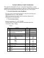
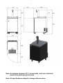
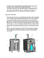
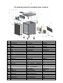
Beverage Keg Cooler
OWNER’S MANUAL
UBC Cool
Made in Ukraine
2
PLEASE CAREFULLY READ THIS MANUAL
This manual is intended for the user. It describes the appliance, correct
installation and operating procedures for safe use. Please read and follow all
safety rules and operating instructions before first use of this product.
1. General information about KegMaster.
The keg cooler is used to prevent beer in a keg from warming up in
temperatures from 10 - 320С (50-90F)
UBC Cool reserves the right to make necessary changes and
modifications to the keg cooler.
2. Technical parameters
Outside temperature 10 - 320С (50-90F)
The keg cooler is intended for use with a standard power line
115V ±10%, 60Hz, 15Amp.
Table.1
№
1.
2.
Parameter
Voltage
Operating current
3.
The final temperature of the product (beer) in
the keg depends on the position of the
termostat handle
4.
5.
6.
7.
8.
9.
10.
11.
12.
13.
Thermostat max. / min. freezing
Net weight
Max number of beer lines
Dimensions without a dispensing tower
Width
Depth
Height
Dimensions with a dispensing tower
Width
Depth
Height
Compressor capacity
Capacity of the compressor at -100С
Coolant R – 134A
Heat exchanger fan
Flow rate
Output
Evaporator fan
Flow rate
Output
Unit.
V/Hz
А
maximum
freezing
minimal
freezing
0
С (0F)
kg. / ft.
pcs
inches
inches
hp
Wt BTU/h
115/60
3.7
+10С (33.8 0F)
+80С (46.4 0F)
-2/+4 (28.4 / 39.2)
64 / 141,1
1-2
23.6
30.98
39.17
23.6
30.98
57.6
kg / lb
1/5
278
949
0,200 /0,441
М3/h
Wt
180х2=360
17х2=34
M3/h
Wt
180
17
3
Note: A minimum clearance of 3" on each side and rear of cabinets
required for optimum performance.
Note: All specifications subject to change without notice.
4
3. Keg cooler accessories:
- refrigerator - 1
- drip tray - 1
- dispensing tower – 1 (optional)
- owner’s manual – 1
- packaging – 1
4. Manufacturer’s warranty
UBC Cool warrants to the original end-user of this product that should it prove
defective due to improper workmanship and/of material under normal use for
a period of one year from the date of installation UBC Cool will repair or
replace, at its option, any defective part without charge for the part.
Replacement parts are warranted for the remainder of the original warranty
period.
The warranty does not include labor of other cost incurred for servicing,
repairing, removing, installing, shipping, or handling of either defective or
replacement parts, or complete unit. Such cost may be covered by a separate
warranty provided by the installing contractor.
This warranty does not cover damages caused by:
(a) accident, abuse, negligence, or misuse;
(b) operating the product in a corrosive atmosphere containing chlorine,
fluorine of any other damaging chemicals;
(c) modification, alteration, poor service practices;
(d) improper matching or application of the product or components;
(e) failure to provide proper maintenance and service to the product
according to manufacture's instructions;
(f) installation or operating of the product in a manner contrary to the
instructions of the manufacturer;
(g) lightning, fluctuations in electrical power or other acts of god. This limited
warranty also excludes al cost of installation, disconnection or dismantling
the product, parts used in connection with normal maintenance such as
air fitters or belts and owner-required maintenance. Consult the
instructions enclosed with the product for information regarding
recommended maintenance.
No one is authorized to change this limited warranty in any respect, or to
create any other obligation or liability in connection with this product.
5
5. Terms of use, transportation and disposal of the keg cooler.
Description of the keg cooler and usage instructions
The keg cooler needs to be equipped with the following accessories
and parts for dispensing of beer: CO2 cylinder, CO2 regulators, air
lines, keg coupler, beer line. Beer is pushed from the keg to the
dispensing tap by CO2. The pressure is set with the regulator.
Keg cooler assembly
The keg cooler’s housing is manufactured of powder coated metal and
has a stainless steel top and inside surfaces (1). The cooler is installed
on four caster wheels with brakes (14, 15). The top of the keg cooler
has metal railings (6), dispensing tower (12) and a drip tray (13) for
spilled beer. A cool beer keg is placed into the keg cooler (3). A coupler
(4) is put into the keg. The coupler has beer lines and a CO2 line (5)
connected to it. A CO2 cylinder with manifolds (9) and a reducer (10) is
kept outside of the keg cooler (8) The CO2 line is drawn inside the keg
cooler to get connected to the coupler trough a hole in the back of the
unit.
The fan, and heat exchanger are located in the refrigeration chamber
(10). Temperature inside the keg cooler is set with a thermostat (2).
The refrigeration units can be reached for service by removing the
covers (11).
6
Safety instructions
WARNING: Instructions pertaining to the risk of fire, electric shock, or
injury to persons.
GROUNDING INSTRUCTIONS
For your personal safety, this appliance must be grounded. In the event of a
malfunction or breakdown, grounding will reduce the risk of electric shock by
providing a path of least resistance for electric current.
This appliance is equipped with a power cord having equipment grounding
conductor and grounding plug. The plug must be plugged into an appropriate
wall outlet that is installed and grounded in accordance with all existing local
codes and ordinances. Consult a qualified electrician or serviceman if the
grounding instructions are not clearly understood or if doubt exists as to
whether your electrical wall outlets are properly grounded.
WARNING
The manufacturer is not responsible for possible damage caused by
improper and unsafe usage of the keg cooler.
Set up instructions.
Unpack the keg cooler and place it in the selected location.
LOCATION
• Selecting the proper location will ensure best performance levels of your
appliance. Choose a location away from heat emitting sources.
• This appliance is designed for "indoor" and "outdoor" use.
• This appliance should not be built-in (recessed) unless adequate ventilation
is provided to maintain proper cooling.
1) Install the dispensing tower onto the top using the fasteners
provided.
Install the faucet facing the door of the keg cooler onto the tower.
2) Install manifolds onto the CO2 cylinder.
3) Connect CO2 hose to the manifold and secure hose by using snap
on clamps (use pliers to snap the clamp tight to assure that there are
no leaks).
4) The length of the CO2 hose should allow reaching the coupler on a
keg inside the keg cooler.
5) Draw the CO2 hose into the keg cooler through a hole in the back.
6) Connect the CO2 hose to the coupler and secure hose by using snap
on clamps.
7) Connect the beer tube to the coupler and secure hose by using snap
on clamps.
8) Connect the other end of the beer tube to the dispensing tower and
secure hose by using plastic snap on clamps.
9) Insert the free end of plastic air hose into the dispensing tower.
7
10) Lock the front wheels with brakes.
11) Place the keg into the cooler.
12) Install the coupler onto the keg.
13) Power up the keg cooler by plugging it into a power outlet. If beer in
the keg is already chilled, it can be served at 5C (40F) after 30 minutes.
WARNING: Please keep a CO2 cylinder away from the back side of the
beer cooler to prevent heating up on the cylinder.
5.1
Cleaning and maintenance.
Automatic defrosting:
There is no need to defrost the refrigerator, because ice depositing on
the evaporator is defrosted automatically.
Ice build-up on the evaporator during compressor operation; will (when
the compressor has cycled off) defrost automatically. Defrost water
collects inside the drain trough and passes through the drain outlet in
the rear wall into a drain pan situated above the compressor, where it
evaporates.
Cleaning the keg cooler:
Always disconnect the power cord before cleaning and/or servicing the
appliance. Do not use coarse or aggressive cleaning agents as they
can damage painted surfaces. Clean the exterior cabinet with warm
water and a mild detergent. Clean the interior with warm water and a
mild detergent, adding one or two spoonfuls of vinegar. After cleaning,
connect the appliance to power supply.
SWITCH OFF AND/OR DISCONNECT THE APPLIANCE WHEN NOT
IN USE:
If you do not intend to use the appliance for long periods of time unplug
the power cord. Take out all foods and clean the appliance. Leave the
door slightly open to reduce mold/mildew from accumulating inside the
cabinet.
5.2
Disposal of the keg cooler
DISPOSAL OF WORN OUT APPLIANCES
• When your keg cooler finally wears out, dispose of it in a safe and
harmless manner. If you have bought this appliance to replace an old
one equipped with a door lock that cannot be opened from the inside,
(lock bolt) make sure the lock is removed, disabled or destroyed before
discarding. This will make it impossible for children to accidentally lock
themselves inside the appliance and suffocate.
8
• The refrigerator system of this appliance is filled with refrigerant and
insulating substances which should be treated and processed
separately. Call your nearest service agent or specialized servicing
center. If you are unable to locate one, contact your local authorities for
proper disposal instructions. Be careful not to damage the any of the
refrigeration lines of the keg cooler.
6 Usage instructions
HELPFUL HINTS TO ASSIST YOU IN SERVING THE PERFECT GLASS OF COLD BEER
6.1 Storage and handling
Draught Beer should be immediately stored in a refrigerated cabinet.
Draught Beer products have a shelf life, which on "average" is 30 days
after the keg is tapped.
By keeping the beer keg pressurized, (with CO2) the shelf life can be
extended (60 days)
6.2. Beer temperature
Optimum temperatures for serving cold beer are 3-5C (36-40F)
Temperatures too cool or too warm may cause flavor loss, off taste and
dispensing problems.
6.3. CO2 pressure
Periodically monitor the pressure regulators to ensure applied operating
pressures remain constant.
(10~12psi/lbs)
6.4. Tapping keg
Do not agitate kegs unnecessarily. If excessive agitation occurs (during
transportation) allow keg to settle for 1 ~2 hours before tapping.
Prior to tapping the keg, ensure the beer faucet is in the off position.
Completely remove the dust cover (identification cap) from the beer
keg.
Check that the keg coupler (handle) is in the up (off) position.
Insert the keg coupler into the locking neck of the beer keg and apply a
turn clockwise to lock into position.
Pull keg coupler handle out and downward until it locks into position.
This activates both the beer and (CO2) pressure line.
The keg is now tapped and ready to draw beer.
DISPENSING BEER
IMPORTANT NOTICE: PLEASE DON'T DRINK AND DRIVE!
Keep beer keg refrigerated at all times.
Never let beer lines empty or allow them to dry out.
Rinse the beer glass with fresh cold water before pouring.
Hold glass at a 45. angle, hold steady, when 2/3 full start to straighten
glass and top it off.
9
When beer is dispensing through the faucet, condensation may form on
the outer surface of the faucet.
This is a normal condition and cannot be avoided. This is caused by
temperature differentials between cold beer flowing across the warmer
ambient surfaces of the inner faucet.
Always make sure the faucet handle is pushed fully back (closed) to
prevent excess dripping.
CLEANING BEER
6.5 Technical service
Technical service of the keg cooler has to be conducted by trained
licensed technicians who are aware of the local electrical safety rules.
No special equipment is required for daily service.
Daily service includes the following: conducting visual inspection for
physical damages of the keg cooler and the power cord, checking the
beer and CO2 hoses for leaks.
WARNING: Never turn the keg cooler over. It might permanently damage
the compressor.
WARNING: Pressure of CO2 must not be above 51 psi/lbs.
7. Emergency situations
In case of a short circuit, immediately cut the power and turn off the
CO2 manifold.
8. Spare Parts
Ordering spare parts
When ordering a spare part please refer to the spare part drawing and
look up the specific spare part number.
Please state carefully the spare part number, the specification and
quantity wanted before you send your order.
If, though, a certain part is not specified in this section, do not hesitate
to contact us for further information.
10
The drawing shows the standard cooler contents
Item
1
2
3
4
5
6
7
8
9
10
11
12
13
14
15
16
Description
Compressor
AIR Condenser
Drip tray
Wheels
Wheels
Bracket door
Nylon bushing
Lock
Cap
Air conduit
Knob ter mostat
Plate for knob ter mostat
Ther mostat
Condenser Fans
Evaporator
Drain tube
17
18
19
20
Cap
Pr otective ring
Drain hose
Bushing
21
Drain hose
22
23
24
25
26
27
28
29
30
31
Cap
Hinge
Bracket door
Cap
Drier filter
Pow er cord
Clamp
Magnetic gas ket
Evaporator fan
Grid
AEA3417YXA (1/5 HP)
type В-13147
cod. 500.06.000.10
type 31-080х32- Р
type 3104- С-080- Р
type S1401
type TO901
type CHF4401
type POP-875, cod.3083
ID=0.984 in.
cod. 076470
cod. 077B7662
cod. 077B7677
type ETC1 C1, cod.077F1045
type 4606 ZWU-879
type В-13148
type 20х75 cod.0001
"Tecumseh"
"KARY ER"
type POP-625, cod.3071
type 22MP01060
PV C , ID=0,71( in). OD=0,87(in)
cod. 500.02.000.01
RA UALCO SK-017-029 RAU- PV C
8766 cod. 049203-001
type POP-1000, cod.3086
type CТ9097D
cod. 500.03.300.00
type 62MP1000
type GR-30
SJTOW 16AWG/3 90°
type 23MP06N34EZ
cod. 510.03.200.00
type 4606 ZWU-879
type LZ30-5
"Heyco"
"KASTOR"
"KASTOR"
"Omniatecnica"
"Omniatecnica"
"Omniatecnica"
"Heyco"
"Rehau"
"Danfoss"
"Danfoss"
"Danfoss"
"EBM"
"KARY ER"
"C.P.Z. sas di Volpin E. & C."
"Rehau"
"Heyco"
"Omniatecnica"
"Rehau"
"DE.NA" SRL
"Rehau"
"EBM"
"EBM"
11
9. Wiring diagram
12
For additional information please call:
1-866-995-9965 (Canada)
1-888-808-9286 (USA East)
1-866-921-1030 (USA West)


![AGIVEN PROGRAM ]](http://vs1.manualzilla.com/store/data/005708142_1-ae1c6d6b32e7a9016e2dede042b38772-150x150.png)