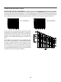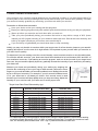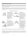
1
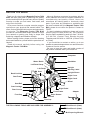
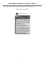
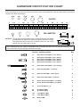
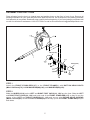
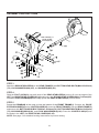
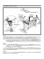
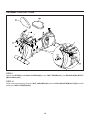
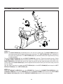
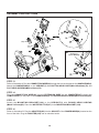
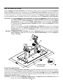
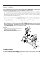
Owner's
Manual
WARNING
Exercise can present a health
risk. Consult a physician
before beginning any exercise
program with this equipment.
If you feel faint or dizzy,
immediately discontinue use
of this equipment. Serious
bodily injury can occur if this
equipment is not assembled
and used correctly. Serious
bodily injury can also occur if
all instructions are not followed.
Keep others and pets away
from equipment when in use.
Always make sure all bolts and
nuts are securely tightened
prior to each use. Follow all
safety instructions in this
manual.
When calling for parts or
service, please specify the
following number :
Model#: 15-7250B
STAMINA PRODUCTS
CAUTION:
Weight on this product should not exceed 300 lbs.
MADE IN CHINA
Product May Vary Slightly
From Pictured.
This Product is Distributed Exclusively by
2040 N. Alliance, Springfield, MO 65803
Customer Service
1 (800) 375-7520
2015, 04
www.staminaproducts.com
2012 Stamina Products, Inc.
TABLE OF CONTENTS
Page
Safety Instructions
Before You Begin
Equipment Warning & Notice Labels
Hardware Identification Chart
Assembly Instructions
Set Up Instructions
Operational Instructions
Computer Instructions
Page
Storage
Maintenance
Conditioning Guidelines
Warm-up and Cool-Down
Warranty
Product Parts Drawing
Parts List
Fax/Mail Ordering Form
2
4
5
6
7
13
14
15
20
20
21
22
23
24
25
27
SAFETY INSTRUCTIONS
This product contains a chemical known to the State of California to cause cancer and birth
defects or other reproductive harm.
Consult your physician before starting this or any exercise program. This is especially important
if you are over the age of 35, have never exercised before, are pregnant, or suffer from any
health problem. This product is for home use only. Do not use in institutional or commercial
applications. Failure to follow all warnings and instructions could result in serious injury or death.
To reduce the risk of serious injury, read the following Safety Instructions before using the
Magnetic Fusion 7250 Bike.
1.
2.
3.
4.
5.
6.
7.
8.
9.
10.
11.
12.
13.
14.
15.
16.
17.
18.
19.
20.
21.
22.
23.
24.
Read all warnings posted on the Magnetic Fusion 7250 Bike.
The Magnetic Fusion 7250 Bike should only be used after a thorough review of the Owner's Manual.
We recommend that two people be available for assembly of this product.
Keep children away from the Magnetic Fusion 7250 Bike. Do not allow children to use or play on the Magnetic
Fusion 7250 Bike. Keep children and pets away from the Magnetic Fusion 7250 Bike when it is in use.
The Magnetic Fusion 7250 Bike is not a freewheeling exercise bike; therefore, pedal speed should be reduced
in a controlled manner to prevent injury from spinning pedals.
Make sure the Magnetic Fusion 7250 Bike is properly assembled and that all nuts and bolts are securely
tightened before use.
It is recommended that you place this exercise equipment on an equipment mat.
Set up and operate the Magnetic Fusion 7250 Bike on a solid level surface. Do not position the Magnetic
Fusion 7250 Bike on loose rugs or uneven surfaces.
Make sure that adequate space is available for access to and around the Magnetic Fusion 7250 Bike.
Adjust the FOOT STANDS(64) and STAND(68) so that the Magnetic Fusion 7250 Bike sits on the floor without
rocking. See page 13 for detailed leveling instructions.
Before using, inspect the Magnetic Fusion 7250 Bike for worn or loose components, and securely tighten or
replace any worn or loose components prior to use.
Before using, always check the SEAT CARRIAGE(7) to be sure it is secure. The ADJUSTMENT KNOB(49)
must be inserted into one of the holes in the REAR FRAME(5) and tightened.
Each user should adjust the seat per instructions on page 14.
Do not attempt to adjust the seat while you are on the Magnetic Fusion 7250 Bike.
Consult a physician prior to commencing an exercise program and follow his/her recommendations in developing
your fitness program. If at any time during exercise you feel faint, dizzy, or experience pain, stop and consult
your physician.
Follow your physician's recommendations in developing your own personal fitness program.
Always choose the workout which best fits your physical strength and flexibility level. Know your limits and train
within them. Always use common sense when exercising.
Do not wear loose or dangling clothing while using the Magnetic Fusion 7250 Bike.
Never exercise in bare feet or socks; always wear proper footwear such as running, walking, or cross training
shoes that fit well, provide foot support, and feature non-skid rubber soles.
Care should be taken in mounting or dismounting the Magnetic Fusion 7250 Bike.
The Magnetic Fusion 7250 Bike should not be used by persons weighing over 300 pounds.
The Magnetic Fusion 7250 Bike should be used by only one person at a time.
Do not ride the Magnetic Fusion 7250 Bike while standing up.
The Magnetic Fusion 7250 Bike is for consumer use only. It is not for use in public or semipublic facilities.
2
CALL US FIRST
Customer Service
1(800) 375-7520
www.staminaproducts.com
THANK YOU FOR PURCHASING THE
Magnetic Fusion 7250 Bike
To help you get started, we have pre-assembled most of your
Magnetic Fusion 7250 Bike at the factory with the exception
of those few parts left unassembled for shipping purposes.
Simply follow the few assembly instructions set forth in this manual.
With regular workouts, you will be getting your body into shape
and be on your way to achieving a happier and healthier lifestyle.
Should you have any questions,
please call our Customer Service Department toll-free number,
1 (800) 375-7520
Monday - Thursday, 7:30 A.M. - 5:00 P.M., Central Time.
Friday, 8:00 A.M. - 3:00 P.M., Central Time.
TELEPHONE
FAX
ONLINE
MAIL
CUSTOMER SERVICE
Tel: 1 (800) 375-7520
CUSTOMER SERVICE
Fax: (417) 889-8064
CUSTOMER SERVICE
[email protected]
www.staminaproducts.com
STAMINA PRODUCTS, INC.
ATTN: Customer Service
P.O. Box 1071
Springfield, MO. 65801-1071
3
BEFORE YOU BEGIN
Thank you for choosing the Magnetic Fusion 7250
Bike. We take great pride in producing this quality
product and hope it will provide many hours of quality
exercise to make you feel better, look better, and
enjoy life to its fullest.
It's a proven fact that a regular exercise program
can improve your physical and mental health. Too
often, our busy lifestyles limit our time and opportunity
to exercise. The Magnetic Fusion 7250 Bike
provides a convenient and simple method to begin
your assault on getting your body in shape and
achieving a happier and healthier lifestyle.
Before reading further, please review the drawing
below and familiarize yourself with the parts that are
labeled.
Read this manual carefully before using the
Magnetic Fusion 7250 Bike.
Although Stamina constructs its products with the
finest materials and uses the highest standards of
manufacturing and quality control, there can
sometimes be missing parts or incorrectly sized
parts. If you have any questions or problems with
the parts included with your Magnetic Fusion 7250
Bike, please do not return the product. Contact us
FIRST!
If a part is missing or defective, please call us toll
free at 1-800-375-7520 (in the U.S.). Our Customer
Service Staff is available to assist you from 7:30 A.M.
to 5:00 P.M. (Central Time) Monday through
Thursday and 8:00 A.M. to 3:00 P.M. (Central Time)
on Friday.
If you would like to contact us online, go to our
website at www.staminaproducts.com and access the
Customer Service section.
Be sure to have the name and model number of
the product available when you contact us.
Computer
Water Bottle
Handlebar
Left Pedal Strap
Upright
Left Pedal
Warning Label
Seat
Upright Sleeve
Back Cushion
Right Cover
Seat Frame
Right Crank
Wheel
Seat Rail
Seat Carriage
Right Pedal
Rear Covers
Front Frame
Adapter
Pulse Sensor
Handrail
Foot Cap
Foot Cap
THE FOLLOWING TOOLS ARE INCLUDED FOR ASSEMBLY :
Allen Wrench (5mm)
Allen Wrench (6mm)
4
Multi-opening Wrench
EQUIPMENT WARNING & NOTICE LABELS
This chart is provided to help identify the warning & notice labels on the Magnetic Fusion 7250 Bike.
Please take a moment to familiarize yourself with all of the warning & notice labels.
Label is larger than actual size
W1
WARNING LABEL(109)
5
HARDWARE IDENTIFICATION CHART
This chart is provided to help identify the hardware used in the assembly process. Place the washers or the
ends of the bolts or screws on the circles to check for the correct diameter. Use the small scale to check the
length of the bolts and screws.
3/16"
1/4"
5/16"
3/8"
1/2"
INCHES
0
1/2
1
1/2
2
1/2
3
1/2
4
1/2
5
1/2
6
in.
mm.
0
10
20
30
40
50
60
70
80
90
100 110 120
130 140 150
MILLIMETERS
6
8
10
length
12
NOTICE: The length of all bolts and screws, except those with flat heads,
is measured from below the head to the end of the bolt or screw.
Flat head bolts and screws are measured from the top of the
head to the end of the bolt or screw.
length
After unpacking the unit, open the hardware bag and make sure that you have all the following items.
Some hardware may be already attached to the part.
Part No. and Description
Qty
74
Bolt, Button Head (M10 x 1.5 x 20mm)
4
70
71
72
75
Bolt, Button Head (M8 x 1.25 x 40mm)
Bolt, Button Head (M8 x 1.25 x 45mm)
Bolt, Button Head (M8 x 1.25 x 53mm)
Bolt, Button Head (M10 x 1.5 x 53mm)
1
2
4
3
76
Bolt, Button Head (M10 x 1.5 x 200mm)
2
78
Bolt, Flat Head (M6 x 1 x 12mm)
2
79
Bolt, Flat Head (M8 x 1.25 x 15mm)
6
82
Bolt, Round Head (M6 x 1 x 38mm)
8
85
86
Screw, Round Head (M4 x 0.7 x 15mm)
Screw, Round Head (M5 x 0.8 x 15mm)
97
Acorn Nut (M10 x 1.5)
2
98
99
Arc Washer (M8)
Arc Washer (M10)
2
8
100
101
Lock Washer (M8)
Lock Washer (M10)
6
9
103
Washer (M8)
4
6
10
4
ASSEMBLY INSTRUCTIONS
Place all parts from the box in a cleared area and position them on the floor in front of you. Remove all
packing materials from your area and place them back into the box. Do not dispose of the packing materials
until assembly is completed. Read each step carefully before beginning. If you are missing a part please call
our toll-free number for assistance 1-800-375-7520 or e-mail us at [email protected].
Wheel(118)
Wheel(118)
STEP 1
Attach the FRONT STABILIZER(117) to the FRONT FRAME(1) with BUTTON HEAD BOLTS
(M8x1.25x53mm)(72), LOCK WASHERS(M8)(100), and WASHERS(M8)(103).
STEP 2
Make the WHEELS(118) on the LEFT and RIGHT FOOT CAPS(119, 120) face the front. Slide the LEFT
and RIGHT FOOT CAPS(119, 120) onto both ends of the FRONT STABILIZER(117) so they fit over the
edges of the LEFT and RIGHT COVERS(115, 116) and secure with ROUND HEAD SCREWS
(M4x0.7x15mm)(85). Screw the FOOT STANDS(64) all the way up into the FRONT STABILIZER(117) on
both sides.
7
ASSEMBLY INSTRUCTIONS
Rear Frame(5), is
inside of Rear
Covers(65, 66)
STEP 3
Attach the REAR STABILIZER(6) to the REAR FRAME(5) with BUTTON HEAD BOLTS(M8x1.25x53mm)
(72), LOCK WASHERS(M8)(100), and WASHERS(M8)(103).
STEP 4
Slide the FOOT CAPS(63) onto both ends of the REAR STABILIZER(6) so they fit over the edges of the
LEFT and RIGHT REAR COVERS(65, 66) and secure with ROUND HEAD SCREWS(M4x0.7x15mm)(85).
Screw the FOOT STANDS(64) all the way up into the REAR STABILIZER(6) on both sides.
STEP 5
Screw the STAND(68) all the way up into the bottom of the FRONT FRAME(1). Connect the PULSE
EXTENSION WIRE(43) to the CONTROL WIRE(25). Insert the FRONT FRAME(1) into the REAR FRAME(5)
and secure with BUTTON HEAD BOLTS(M10x1.5x20mm)(74), BUTTON HEAD BOLTS(M10x1.5x53mm)
(75), ARC WASHERS(M10)(99), and LOCK WASHERS(M10)(101). Press the COVER PLUGS(67) into
the holes in the LEFT and RIGHT REAR COVERS(65, 66).
NOTE: See page 13 for detailed leveling instructions to prevent rocking.
8
ASSEMBLY INSTRUCTIONS
Use this set of attachment
holes for assembly.
Socket of Pulse
Extension Wire(43)
STEP 6
Attach the SEAT FRAME(114) to the SEAT CARRIAGE(7) with BUTTON HEAD BOLTS(M10x1.5x200mm)
(76), WASHERS(M10)(99), LOCK WASHERS(M10)(101), and ACORN NUTS(M10x1.5)(97).
NOTE: The four attachment holes on each side of the SEAT FRAME(114) allow the SEAT FRAME(114) to
be attached in two different positions: one to position you closer to the HANDLEBAR(4) and one
further away. At this point of assembly, use the holes at the back so the Seat Assembly is closer to
the HANDLEBAR(4). After all assembly steps, refer to page 14 for the details of seat adjustment.
STEP 7
NOTE: The PULSE SENSOR WIRES(55) go through the tube of the HANDRAIL(9). Be careful not to
damage the wires with the BUTTON HEAD BOLTS(M8x1.25x45mm)(71) when attaching the
HANDRAIL(9) to the SEAT CARRIAGE(7).
To attach the HANDRAIL(9), position the HANDRAIL(9) under the SEAT CARRIAGE(7) as shown in the
above illustration and secure with BUTTON HEAD BOLTS(M8x1.25x45mm)(71), ARC WASHERS(M8)
(98), and LOCK WASHERS(M8)(100).
STEP 8
Refer to the inset drawing. Plug the PULSE SENSOR WIRE(55) into the SOCKET of the PULSE EXTENSION
WIRE(43) located on the SEAT RAIL(45).
9
ASSEMBLY INSTRUCTIONS
STEP 9
Attach the SEAT(59) and BACK CUSHION(60) to the SEAT FRAME(114) with ROUND HEAD BOLTS
(M6x1x38mm)(82).
STEP 10
Refer to the inset drawing. Press the NUT CAPS(M10)(53) onto the NYLOCK NUTS(M10x1.5)(95) on both
sides of the SEAT CARRIAGE(7).
10
ASSEMBLY INSTRUCTIONS
STEP 11
NOTE: The RIGHT PEDAL(41) has R stamped on the end of the pedal shaft. The RIGHT PEDAL(41) has
right hand threads and is tightened by turning clockwise. The LEFT PEDAL(39) has L stamped on
the end of the pedal shaft. The LEFT PEDAL(39) has left hand threads and is tightened by turning
counterclockwise.
Thread the RIGHT PEDAL(41) into the RIGHT CRANK(36) as shown. Tighten the pedal securely. Select
the RIGHT PEDAL STRAP(42) which has R marked on it. Snap the two hole end to the inside edge of the
RIGHT PEDAL(41). Insert the other end of the strap through the slot and snap the strap to the hook on the
outside edge of the RIGHT PEDAL(41). Select adjustment holes which allow your foot to be easily removed
from the pedals.
Use the same procedure to attach the LEFT PEDAL(39) to the LEFT CRANK(35) and snap the LEFT
PEDAL STRAP(40) to the LEFT PEDAL(39).
STEP 12
Slide the UPRIGHT SLEEVE(32) over the UPRIGHT(3). Connect the CONNECTION WIRE(26) to the
CONTROL WIRE(25). Insert the UPRIGHT(3) onto the FRONT FRAME(1) and secure with FLAT HEAD
BOLTS(M8x1.25x15mm)(79). Slide the UPRIGHT SLEEVE(32) down to cover the bolt heads.
11
ASSEMBLY INSTRUCTIONS
A.
B.
Socket of
Power Wire(28)
STEP 13
Refer to illustration A. Run the CONNECTION WIRE(26) through the hole in the plate on the HANDLEBAR(4).
Attach the HANDLEBAR(4) to the UPRIGHT(3) with BUTTON HEAD BOLT(M8x1.25x40mm)(70) and
FLAT HEAD SCREWS(M6x1x12mm)(78).
STEP 14
Plug the CONNECTION WIRE(26) into the EXTENSION WIRE on the COMPUTER(27). Attach the
COMPUTER(27) to the plate on the HANDLEBAR(4) with ROUND HEAD SCREWS(M5x0.8x15mm)(86).
STEP 15
Attach the MOUNTING BRACKET(106) to the UPRIGHT(3) with ROUND HEAD SCREWS
(M4x0.7x15mm)(85). Place the WATER BOTTLE(107) in the MOUNTING BRACKET(106).
STEP 16
Refer to illustration B. Plug the ADAPTER(105) into the SOCKET of the POWER WIRE(28) located on the
front of the bike. Plug the ADAPTER(105) into an electrical outlet.
12
SET UP INSTRUCTIONS
Place the Magnetic Fusion 7250 Bike in the area where it will be used. It is recommended that the Magnetic
Fusion 7250 Bike be placed on an equipment mat. The Magnetic Fusion 7250 Bike is approximately 55 3/4
inches long x 24 3/8 inches wide x 50 3/8 inches tall (max.). (These dimensions may vary up to one inch.)
An area 4 feet wide x 7 feet long is required for safe operation of the Magnetic Fusion 7250 Bike. Make
sure that adequate space is available for access to and passage around the Magnetic Fusion 7250 Bike.
LEVELING: To level the Magnetic Fusion 7250 Bike, first screw the STAND(68) located in the middle of
the FRONT FRAME(1) all the way up into the FRONT FRAME(1) so that it is not touching the
floor. Adjust the four FOOT STANDS(64) on each of the four corners, two under FRONT
STABILIZER(2) and two under the REAR STABILIZER(6). When the FOOT STANDS(64)
are adjusted and the Magnetic Fusion 7250 Bike is stable, rotate the STAND(68) to make it
contact with the floor.
While you are adjusting the FOOT STANDS(64) the STAND(68) must not be in contact with
the floor. Only after the Magnetic Fusion 7250 Bike has been stabilized with the FOOT
STANDS(64) will you position the STAND(68) so it is in contact with the floor to provide extra
stability for the frame.
MOVING: The Magnetic Fusion 7250 Bike has a pair of WHEELS(118) built into the LEFT and RIGHT
FOOT CAPS(119, 120) at the front. Lift up the REAR STABILIZER(6) to move the Magnetic
Fusion 7250 Bike.
EQUIPMENT MAT
(not included)
FUNCTION INSPECTION:
Visually inspect the Magnetic Fusion 7250 Bike to verify that assembly is as shown in the above illustration.
Check the function of the Magnetic Fusion 7250 Bike by turning the crank slowly through one complete
revolution to verify that the drive train functions properly. Use the UP and DOWN buttons on the COMPUTER
(27) to select a program and verify that the Magnetic System provides different tensions. Refer to the
COMPUTER INSTRUCTIONS on pages 15 to 19.
CAUTION: Locate and read the WARNING LABEL(109) on the Magnetic Fusion 7250 Bike. Make sure
that all users read the WARNING LABEL(109).
13
OPERATIONAL INSTRUCTIONS
SEAT ADJUSTMENT
Proper seat adjustment is important. There are nine adjustment holes in the SEAT RAIL(45). These adjustment
holes allow users to adjust the position of the seat up and down for efficient exercise.
1. Be sure the ADJUSTMENT KNOB(49) is tightened. Sit on the seat and place your feet on the pedals.
You should be able to move through a complete pedal stroke without locking your knees or shifting your
hips on the seat. The seat is too close to the pedals if you have more than a slight bend in your knees at
the bottom of the pedal stroke. The seat is too far from the pedals if you have to completely straighten
your knees at the bottom of the pedal stroke.
2. To adjust the seat height, rotate the ADJUSTMENT KNOB(49) counterclockwise until the pin releases
when the knob is pulled. Pull the ADJUSTMENT KNOB(49) and slide the SEAT CARRIAGE(7) up or
down to desired position. Lock the SEAT CARRIAGE(7) in position by inserting the pin of the
ADJUSTMENT KNOB(49) into one of the adjustment holes in the SEAT RAIL(45), then rotate the
ADJUSTMENT KNOB(49) clockwise to lock the SEAT CARRIAGE(7) securely.
3. If you feel the Seat Assembly is too close to the HANDLEBAR(4) even after you have adjusted it up or
down, change the set of attachment holes on the SEAT FRAME (114) to those closer to the front. By
changing attachment holes, the Seat Assembly will move 1.5 inches back and position you further away
from the HANDLEBAR(4). Refer to step 6 on page 9 for details.
CAUTION:
1. Do not attempt to adjust the seat while you are on
the Magnetic Fusion 7250 Bike.
2. Always tighten the ADJUSTMENT KNOB(49) after
adjusting the seat to a new position.
LOAD ADJUSTMENT
The load level of Magnetic Fusion 7250 Bike can be changed at any time during your workout. Use the UP
and DOWN buttons on the COMPUTER(27) to increase or decrease your intensity level. Press the UP
button to increase the load level. Press the DOWN button to decrease the load level.
14
COMPUTER INSTRUCTIONS
Your Magnetic Fusion 7250 Bike utilizes a magnetic braking system to create resistance for your workout.
You control the amount and pattern of this resistance by means of the advanced computer console mounted
at the center of the handlebar. We recommend that you use this computer console to vary your workout
from session to session and note your progress toward your fitness goals. When used regularly in this way,
the computer console can become an important source of motivation and interest which will help keep you
on track.
BUTTONS:
PROGRAM BUTTONS: The Magnetic Fusion 7250 Bike has twelve preset workout programs. Select the
desired program from the twelve buttons on the computer.
/ UP: Press to increase the values of the setting mode. Press to increase the level of the
workload when running a program.
/ DOWN: Press to decrease the values of the setting mode. Press to decrease the level of
the workload when running a program.
ENTER: Press to select the values of the various settings.
START / STOP: Press to start the selected program. Press the START / STOP button to stop the
program. Press and hold the START / STOP button down for four seconds to reset
all of the function values to zero.
15
COMPUTER INSTRUCTIONS
PROGRAM NUMBER
HEART RATE CONTROL PROGRAMS
TIME
CALORIE
SPEED
AGE / TARGET H.R.
DISTANCE
HEART RATE
HEART SYMBOL
PROGRAM PROFILE
LCD DISPLAY INSTRUCTIONS
PROGRAM: Displays the selected program during exercise, from P1 to P12.
TIME: Displays the time. Counts upward from one second to 99:59 minutes. Counts down from
preset value.
SPEED: Displays the current speed from zero to 99.9 miles per hour.
DISTANCE: Displays the distance from zero to 999.9 miles.
CALORIE: Displays the calorie consumption from zero to 999.9 Kcal.
NOTE: The calorie readouts are an estimate for an average user. It should be used only as
a comparison between workouts on this unit.
AGE / When you select the Heart Rate Control Programs, P11 or P12, you must input your age.
TARGET H.R. : This value affects only the Heart Rate Control Programs. Press ENTER button until the
AGE/TARGET H.R. display is flashing and use " / " buttons to input your age.
When Heart Rate Control Programs, P11 or P12, are selected, the target heart rate value
will be shown during exercise.
HEART RATE: Displays heart rate in beats per minute from 40 to 240 beats per minute.
To display the heart rate, you must grasp the Pulse Sensors on both sides of the handrail,
one in each hand. The heart symbol " " will begin flashing when the computer senses your
heart rate. Your heart rate will be displayed approximately five (5) seconds after the heart
icon is displayed. If you do not place your hands correctly and 60 seconds passes without
a heart rate reading, the computer will turn off the heart rate circuit. If this occurs, press the
ENTER button to restart the heart rate circuit, place your hands back on the Pulse Sensors
correctly, and the heart rate readout will appear.
16
COMPUTER INSTRUCTIONS
PROGRAM DESCRIPTIONS
This computer contains 12 different programs. You can preset the program time and the computer will
divide the time chosen into 10 intervals. If you do not set the program time in advance, the computer will
default to a 30 minute workout time.
(P1) MANUAL
MANUAL PROGRAM: P1 is a manual program allowing the user to have
full manual control of the workload. Use the " " button to increase the
load. Use the " " button to decrease the load.
PRESET PROGRAMS: P2 to P10 are preset automatic programs. The profiles are shown on the face of
the computer. Use the " " button to increase the load level of the program. Use the " " button to decrease
the load level of the program.
(P2) ROLLING
(P3) VALLEY
(P4) FAT BURN
(P5) RAMP
(P6) FITNESS
(P7) RANDOM
(P8) PLATEAU
(P9) INTERVAL
(P10) MOUNTAIN
17
COMPUTER INSTRUCTIONS
HEART RATE CONTROL PROGRAMS: P11 and P12 are preset automatic Heart Rate Control Programs.
You must input your age and always hold the pulse sensors on the HANDRAIL(9) with both hands when
using the Heart Rate Control Programs. P11 is programmed to use 60% of your maximum heart rate as
your target heart rate zone workout goal, and P12 is programmed to use 85% of your maximum heart rate
as your target heart rate zone workout goal; therefore, P11 will be a less intense workout than P12.
(P11) 60% MAX H.R.
(P12) 85% MAX H.R.
As you exercise, the program will monitor your pulse
and adjust the workload automatically to keep you
working within a zone that is plus or minus 5 beats per
minute of your target heart rate. Your age and the
program you selected will determine your heart rate
zone.
For example, if your age is 30, your maximum heart
rate is 190. If you selected P11, your workout will keep
you within a target heart rate zone that is plus or minus
5 beats per minute of 60% of your maximum heart
rate: 190 x 60% = 114 so your heart rate zone is 109
to 119. The program will monitor your pulse and adjust
the workload automatically to keep your pulse within
the heart rate zone during your workout.
18
COMPUTER INSTRUCTIONS
COMPUTER OPERATION
STEP 1: POWER ON
Pedaling or press any button.
STEP 2 : SELECT PROGRAM
Select and press one of the PROGRAM BUTTONS to enter the desired program.
STEP 3: SET THE PROGRAM TIME OR CALORIE (and input age for Heart Rate Control Programs)
The TIME function mode will appear with the display flashing "0:00". You have options to do the following:
1. Press START / STOP button to start the program. All of the function values will count up from zero.
2. Use " / " buttons to set the program time, from one minute up to 99 minutes with 1 minute increments.
Or, you can keep TIME as "0:00" and press the ENTER button to enter the mode to set the CALORIE.
Use " / " buttons to set the CALORIE, from 10 Kcal. up to 9990 Kcal. with 10 Kcal. increments. Press
the ENTER button to confirm the setting. Press the START / STOP button to start the program.
When you select the Heart Rate Control Programs, P11 or P12, you must input your age. Press ENTER
button until the AGE/TARGET H.R. display is flashing and use " / " buttons to input your age. Press the
ENTER button to confirm the setting. Press the START / STOP button to start the program.
NOTE: 1. The program will not start until you press the START / STOP button.
2. The computer will count down from the function values that you set, Time and Calorie. When
one of the two function values counts down to zero, the computer will remind you with an
audible alarm and start counting up this function value. Another function value will continue to
count down.
3. If you don't set the program time, the computer will count up from one second up to 99:59
minutes, and use the default workout time, 30 minutes, to cycle run the program profile.
OPERATION DESCRIPTIONS
1. To stop a running program, press the START / STOP button. In this mode, you can press the
START / STOP button again to continue to run the current program. Or, you can use the PROGRAM
BUTTONS to select a new program. The function values of DISTANCE and CALORIE will continue to
accumulate.
2. When you complete a program, press the START / STOP button to stop the program. You can use the
PROGRAM BUTTONS to select a new program. The function values of DISTANCE and CALORIE will
continue to accumulate. This will allow you to run several programs and still know the total DISTANCE
and CALORIE during the workout.
3. If you want to restart with a new program, press and hold the START / STOP button down for four
seconds to reset all of the function values to zero. Use the PROGRAM BUTTONS to select a new
program.
4. The computer will shut off automatically after 4 minutes of inactivity, and the function values, DISTANCE
and CALORIE, will be kept.
POWER SOURCE:
The computer uses the ADAPTER(105) as a power source. Use the Magnetic Fusion 7250 Bike with the
adapter plugged into an electrical outlet.
19
STORAGE
1. To store the Magnetic Fusion 7250 Bike, simply keep it in a clean dry place.
2. Adjust the SEAT CARRIAGE(7) to the lowest position. The Magnetic Fusion 7250 Bike is approximately
55 3/4 inches long x 24 3/8 inches wide x 50 3/8 inches tall (max.). These dimensions will vary. Please
measure your Magnetic Fusion 7250 Bike if exact dimensions are needed.
3. To move the Magnetic Fusion 7250 Bike, lift the REAR STABILIZER(6) and the bike will roll on the
WHEELS(118) on the FRONT STABILIZER(117).
MAINTENANCE
The safety and integrity designed into the Magnetic Fusion 7250 Bike can only be maintained when the
Magnetic Fusion 7250 Bike is regularly examined for damage and wear. Special attention should be given
to the following:
1. Use the PROGRAM BUTTONS on the COMPUTER(27) to select a program and verify that the Magnetic
System provides different tensions. The Magnetic System should provide many years of use.
2. Use a wrench to verify that the pedals are tightened securely. If tightening is required, remember that the
left pedal has left hand threads and is tightened by turning counterclockwise. The right pedal has right
hand threads that are tightened by turning clockwise.
3. Verify that the WARNING LABEL(109) is in place and easy to read. Call Stamina Products immediately
at 1-800-375-7520 for a replacement WARNING LABEL(109) if it is missing or damaged.
4. It is the sole responsibility of the user/owner to ensure that regular maintenance is performed.
5. Worn or damaged components shall be replaced immediately or the Magnetic Fusion 7250 Bike removed
from service until repair is made.
6. Only Stamina Products supplied components shall be used to maintain/repair the Magnetic Fusion
7250 Bike.
7. Keep your Magnetic Fusion 7250 Bike clean by wiping it off with an absorbent cloth after use.
20
CONDITIONING GUIDELINES
How you begin your exercise program depends on your physical condition. If you have been inactive for
several years or are severely overweight, start slowly and increase your workout time gradually. Increase
your workout intensity gradually by monitoring your heart rate while you exercise.
Remember to follow these essentials:
Have your doctor review your training and diet programs.
Begin your training program slowly with realistic goals that have been set by you and your physician.
Warm up before you exercise and cool down after you work out.
Take your pulse periodically during your workout and strive to stay within a range of 60% (lower
intensity) to 90% (higher intensity) of your maximum heart rate zone. Start at the lower intensity, and
build up to higher intensity as you become more aerobically fit.
If you feel dizzy or lightheaded you should slow down or stop exercising.
Initially you may only be able to exercise within your target zone for a few minutes; however, your aerobic
capacity will improve over the next six to eight weeks. It is important to pace yourself while you exercise so
you don't tire too quickly.
To determine if you are working out at the correct intensity, use a heart rate monitor or use the table below.
For effective aerobic exercise, your heart rate should be maintained at a level between 60% and 90% of
your maximum heart rate. If just starting an exercise program, work out at the low end of your target heart
rate zone. As your aerobic capacity improves, gradually increase the intensity of your workout by increasing
your heart rate.
Measure your heart rate periodically during your workout by stopping the
exercise but continuing to move your legs or walk around. Place two or three
fingers on your wrist and take a six second heartbeat count. Multiply the results
by ten to find your heart rate. For example, if your six second heartbeat count
is 14, your heart rate is 140 beats per minute. A six second count is used
because your heart rate will drop rapidly when you stop exercising. Adjust the
intensity of your exercise until your heart rate is at the proper level.
wrist pulse
Target Heart Rate Zone Estimated by Age*
Age
Target Heart Rate Zone
(55%-90% of Maximum Heart Rate)
Average Maximum
Heart Rate 100%
20 years
110-180 beats per minute
200 beats per minute
25 years
107-175 beats per minute
195 beats per minute
30 years
105-171 beats per minute
190 beats per minute
35 years
102-166 beats per minute
185 beats per minute
40 years
99-162 beats per minute
180 beats per minute
45 years
97-157 beats per minute
175 beats per minute
50 years
94-153 beats per minute
170 beats per minute
55 years
91-148 beats per minute
165 beats per minute
60 years
88-144 beats per minute
160 beats per minute
65 years
85-139 beats per minute
155 beats per minute
70 years
83-135 beats per minute
150 beats per minute
* For cardiorespiratory training benefits, the American College of Sports Medicine recommends working
out within a heart rate range of 55% to 90% of maximum heart rate. To predict the maximum heart
rate, the following formula was used: 220 - Age = predicted maximum heart rate
21
WARM-UP and COOL-DOWN
Warm-Up The purpose of warming up is to prepare your body for exercise and to minimize injuries.
Warm up for two to five minutes before strength training or aerobic exercising. Perform activities that raise
your heart rate and warm the working muscles. Activities may include brisk walking, jogging, jumping jacks,
jump rope, and running in place
Stretching Stretching while your muscles are warm after a proper warm-up and again after your strength
or aerobic training session is very important. Muscles stretch more easily at these times because of their
elevated temperature, which greatly reduces the risk of injury. Stretches should be held for 15 to 30 seconds.
Do not bounce.
Suggested Stretching Exercises
Lower Body Stretch
Floor Stretch
Place feet shoulder-width
apart and lean forward.
Keep this position for 30
seconds using the body as a
natural weight to stretch the
backs of the legs.
DO NOT BOUNCE!
When the pull on the back
of the legs lessens,
gradually try a lower
position.
While sitting on the floor,
open the legs as wide as
possible. Stretch the upper
body toward the knee on the
right leg by using your arms
to pull your chest to your
thighs. Hold this stretch 10
to 30 seconds.
DO NOT BOUNCE!
Do this stretch 10 times.
Repeat the stretch with the
left leg.
Bent Torso Pulls
Bent Over Leg Stretch
While sitting on the floor,
have legs apart, one leg
straight and one knee bent.
Pull the chest down to touch
the thigh on the leg that is
bent, and twist at the waist.
Hold this position at least 10
seconds. Repeat 10 times
on each side.
Stand with feet shoulderwidth apart and lean forward
as illustrated. Using the
arms, gently pull the upper
body towards the right leg.
Let the head hang down.
DO NOT BOUNCE!
Hold the position a minimum
of 10 seconds. Repeat
pulling the upper body to the
left leg. Do this stretch
several times slowly.
Remember to always check with your physician before starting any exercise program.
Cool-Down The purpose of cooling down is to return the body to its normal, or near normal, resting state
at the end of each exercise session. A proper cool-down slowly lowers your heart rate and allows blood to
return to the heart. Your cool-down should include the stretches listed above and should be completed after
each strength training session.
22
LIMITED WARRANTY
MODEL 15-7250B
WARRANTY
Stamina Products, Inc. warrants that this product will be free from defects in materials and workmanship
under normal use, service and proper operation for a period of 90 days on the parts and five years on the
frame from the date of the original purchase from an authorized retailer. THIS WARRANTY SHALL NOT
APPLY TO ANY PRODUCT WHICH HAS BEEN SUBJECT TO COMMERCIAL USE, ABUSE, MISUSE,
ALTERATION OF ANY TYPE OR CAUSE OR TO ANY DEFECT OR DAMAGE CAUSED BY REPAIR,
REPLACEMENT, SUBSTITUTION OR USE WITH PARTS OTHER THAN PARTS PROVIDED BY STAMINA
PRODUCTS, INC. Commercial use includes use of the product in athletic clubs, health clubs, spas,
gymnasiums, exercise facilities, and other public or semipublic facilities whether or not the product's use is
in furtherance of a profit making enterprise, and all other use which is not for personal, family, or household
purposes.
To implement this limited warranty, send a written notice stating your name, date, and place of purchase and
a brief description of the defect along with your receipt to Stamina Products, Inc. P.O. Box 1071, Springfield
Missouri, USA, 65801-1071, or email us at [email protected], or call us at
1-800-375-7520. If the defect is covered under this limited warranty, you will be requested to return the
product or part to us for free repair or replacement at our option. NO ACTION FOR BREACH OF THIS
LIMITED WARRANTY MAY BE COMMENCED MORE THAN ONE (1) YEAR AFTER THE DATE THE
ALLEGED BREACH WAS OR SHOULD HAVE BEEN DISCOVERED. NO ACTION FOR BREACH OF
ANY IMPLIED WARRANTY MAY BE COMMENCED MORE THAN ONE (1) YEAR AFTER DELIVERY OF
THE PRODUCT TO THE PURCHASER. This limited warranty is not transferable. IF ANY PART OF THE
PRODUCT IS NOT IN COMPLIANCE WITH THIS LIMITED WARRANTY OR ANY IMPLIED WARRANTY,
THE REMEDY OF REPAIR OR REPLACEMENT IS THE EXCLUSIVE REMEDY AVAILABLE TO YOU. In
the event that the purchaser makes any claim under this limited warranty or any implied warranty, the
Warrantor reserves the right to require the product to be returned for inspection, at the purchaser's expense,
to the Warrantor's premises in Springfield, Missouri. Return of the enclosed warranty registration card is not
required for warranty coverage, but is merely a way of establishing the date and place of purchase.
Stamina Products, Inc. SHALL NOT BE LIABLE FOR THE LOSS OF USE OF ANY PRODUCT, LOSS OF
TIME, INCONVENIENCE, COMMERCIAL LOSS OR ANY OTHER INDIRECT, CONSEQUENTIAL,
SPECIAL OR INCIDENTAL DAMAGES DUE TO BREACH OF THE ABOVE WARRANTY OR ANY IMPLIED
WARRANTY.
This limited warranty is the only written or express warranty given by Stamina Products, Inc. This warranty
gives you specific legal rights, and you may also have other legal rights which vary from state to state.
ANY OTHER RIGHT WHICH YOU MAY HAVE, INCLUDING ANY IMPLIED WARRANTY OR
MERCHANTABILITY OR FITNESS FOR A PARTICULAR PURPOSE, IS LIMITED IN DURATION TO THE
DURATION OF THIS WARRANTY.
The laws in some jurisdictions restrict the rights of manufacturers and distributors of consumer goods to
disclaim or limit implied warranties and consequential and incidental damages with respect thereto. If any
such law is found to be applicable, the foregoing disclaimers and limitations of and on implied warranties
and consequential and incidental damages with respect thereto shall be disregarded and shall be deemed
not to have been made to the extent necessary to comply with such legal restriction.
23
PRODUCT PARTS DRAWING
FRONT
BACK
24
PARTS LIST
PART#
1
3
4
5
6
7
9
10
11
12
13
14
15
16
17
18
19
20
21
22
23
24
25
26
27
28
29
30
31
32
35
36
37
38
39
40
41
42
43
44
45
46
47
48
49
50
51
52
53
54
55
56
57
58
59
60
61
PART NAME
Front Frame
Upright
Handlebar
Rear Frame
Rear Stabilizer
Seat Carriage
Handrail
Pulley and Axle
Bearing (6003Z)
Bearing Washer (M17)
C Ring (17mm)
V-Ribbed Belt
Idler Arm
Idler Wheel
Idler Wheel Spacer
Tension Spring
Magnetic Unit
Lock Washer (3/8")
Thin Nut (3/8" - 26 x 5/32" thick)
Nut (3/8" - 26 x 9/32" thick)
Tension Cable
Motor
Control Wire
Connection Wire
Computer
Power Wire
Nut
Sensor Wire
Magnet
Upright Sleeve
Left Crank
Right Crank
Flange Bolt (M8 x 1.25 x 20mm)
Crank Cap
Left Pedal
Left Pedal Strap
Right Pedal
Right Pedal Strap
Pulse Extension Wire
Securing Plug
Seat Rail
Rail Cap
Stopper
Support Plate
Adjustment Knob
Roller
Roller Support
C Ring (10mm)
Nut Cap (M10)
Grommet Plug
Pulse Sensor Wire
Pulse Sensor
Hand Grip
Round Dome Plug (25.4mm)
Seat
Back Cushion
Foam Grip
25
QTY
1
1
1
1
1
1
1
1
2
2
2
1
1
1
1
1
1
2
1
3
1
1
1
1
1
1
1
1
1
1
1
1
2
2
1
1
1
1
1
1
1
2
4
1
1
8
4
8
8
1
1
2
2
4
1
1
2
PARTS LIST
PART#
63
64
65
66
67
68
69
70
71
72
73
74
75
76
77
78
79
80
81
82
84
85
86
87
88
89
90
91
92
93
94
95
97
98
99
100
101
102
103
104
105
106
107
108
109
110
111
112
113
114
115
116
117
118
119
120
121
PART NAME
Foot Cap
Foot Stand
Left Rear Cover
Right Rear Cover
Cover Plug
Stand
Screw, Round Head (M4 x 50mm)
Bolt, Button Head (M8 x 1.25 x 40mm)
Bolt, Button Head (M8 x 1.25 x 45mm)
Bolt, Button Head (M8 x 1.25 x 53mm)
Bolt, Button Head (M10 x 1.5 x 15mm)
Bolt, Button Head (M10 x 1.5 x 20mm)
Bolt, Button Head (M10 x 1.5 x 53mm)
Bolt, Button Head (M10 x 1.5 x 200mm)
Bolt, Hex Head (M8 x 1.25 x 70mm)
Bolt, Flat Head (M6 x 1 x 12mm)
Bolt, Flat Head (M8 x 1.25 x 15mm)
Bolt, Flat Head (M8 x 1.25 x 20mm)
Bolt, Flat Head (M10 x 1.5 x 35mm)
Bolt, Round Head (M6 x 1 x 38mm)
Screw, Flat Head (M5 x 0.8 x 20mm)
Screw, Round Head (M4 x 0.7 x 15mm)
Screw, Round Head (M5 x 0.8 x 15mm)
Screw, Round Head (M4 x 15mm)
Screw, Round Head (M4 x 25mm)
Screw, Round Head (M5 x 10mm)
Screw, Round Head (M5 x 15mm)
Nut (M8 x 1.25)
Nylock Nut (M5 x 0.8)
Nylock Nut (M6 x 1)
Nylock Nut (M8 x 1.25)
Nylock Nut (M10 x 1.5 x 7mm thick)
Acorn Nut (M10 x 1.5)
Arc Washer (M8)
Arc Washer (M10)
Lock Washer (M8)
Lock Washer (M10)
Large Washer (ø16 x ø32 x 0.5mm thick)
Washer (M8)
Washer (M10)
Adapter, Output 7.5V DC, 700mA
Mounting Bracket
Water Bottle
Round Plug (25.4mm)
Warning Label
Allen Wrench (5mm)
Allen Wrench (6mm)
Multi-Opening Wrench
Manual
Seat Frame
Left Cover
Right Cover
Front Stabilizer
Wheel
Left Foot Cap
Right Foot Cap
Bolt, Round Head (M6 x 1 x 75mm)
26
QTY
2
4
1
1
4
1
1
1
2
4
7
4
3
2
2
2
6
1
1
8
3
10
4
12
11
4
1
2
3
2
1
9
2
2
8
6
16
1
4
8
1
1
1
2
1
1
1
1
1
1
1
1
1
2
1
1
2
FAX/MAIL ORDERING FORM
Please do not return the product. For your convenience, Stamina's Customer Service Department can be
reached by email at [email protected] or toll free at 1-800-375-7520 (in the U.S.).
Should a part be missing or a defective part found, please call us from 7:30 A.M. to 5:00 P.M. Central Time,
Monday through Thursday and 8:00 A.M. to 3:00 P.M. on Friday or fill out the fax sheet ordering form below
and fax it to (417) 889-8064. Our Customer Service Department will be able to assist you with your problem
and the part will be mailed directly to your house.
TELEPHONE
FAX
ONLINE
MAIL
CUSTOMER SERVICE
Tel: 1 (800) 375-7520
CUSTOMER SERVICE
Fax: (417) 889-8064
CUSTOMER SERVICE
[email protected]
www.staminaproducts.com
STAMINA PRODUCTS, INC.
ATTN: Customer Service
P.O. Box 1071
Springfield, MO. 65801-1071
Detach and Mail or Fax the Form Below
Stamina Products, Inc.
P.O. Box 1071
Springfield, MO 65801-1071
Mr./Ms:
Address:
City:
Apt. #:
Zip Code:
State:
IMPORTANT : We must have your phone number in order to process the order!
Phone #: (
)
Date Purchased:
Model #:
Purchased From:
Work Phone #: (
)
IMPORTANT : Before filling out the form below make sure you have the right information.
Refer to the parts list to make sure you're ordering the right parts!
EXAMPLE:
PART #
DESCRIPTION
QUANTITY
1
Rear Unit Assembly
1