1
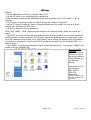
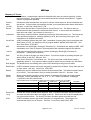
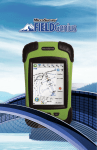
AGPS-Topo
AGPS-Topo
User manual
Advanced Geo Positioning Solutions, Inc.
www.agpsinc.com
AGPS-Topo Concepts Documentation............................................................................ 2
Start the AGPS program. ................................................................................................ 3
To work on a different job:............................................................................................... 4
To work on the same job: ................................................................................................ 4
Many questions: .............................................................................................................. 4
Coordinate setup ............................................................................................................. 5
Working screen ............................................................................................................... 8
Rod Length...................................................................................................................... 8
Point Label ...................................................................................................................... 8
Capturing a Control Point: ............................................................................................... 8
Rotating a grid: .............................................................................................................. 10
Quitting the program:..................................................................................................... 11
Glossary of Terms: ........................................................................................................ 12
Page 1 of 12
Revision: 10/5/2009
AGPS-Topo
AGPS-Topo Concepts Documentation
Purpose of Program :
To rapidly and easily capture many points that define the surface that is being measured. Usually,
these points will be loaded into another program that can make contour lines and/or compute
volumes.
Files Used :
Most of the files you work with are stored in the directory named "C:\AMW\DATA" . See the icons
named "Data", "Datacmd" and "Load Data From Floppy" in the "C:\AMW" folder you see upon startup.
CTL File : Is used for "Control Points" used in setting up the "Location Instrument" ( usually GPS or
Total-Station ). If your jobname is "MITS1" you will need a CTL file named "MITS1.CTL" . One may
be automatically built for you or can be copied from "AMODEL.CTL" or "SAMPLE.CTL" . This file
uses the following columns: “Name Northing(N) Easting(E) Elevation(Z) Description”. Points
from this file will be displayed on your plot window as small triangles. *What is a Control Point? Sometimes
called a benchmark, this point is a known world feature in which coordinates are also known. Control points are
important to make your coordinates match those used earlier.
SVY File : This file will contain all points captured when doing a topo. Also, "Location Instrument"
setup information and other relevant information is logged to this file. This file will be created for you
and will start out empty when you create a new job. If your jobname is "MITS1" you will have a file
named "MITS1.SVY". See "SAMPLE.SVY". Points from this file will be displayed on your plot
window as dots. When the data capturing work is done, this file is usually used to generate a "NEZ"
(Northing,Easting,Elevation) file and/or a "DXF" (Drawing Exchange File) that can be loaded into
another program.
DRW File : This optional file defines a background-drawing that will be shown on the plot window
along with other data.You can easily build this file from a "DXF" file that comes out of most "CAD"
(computer-aided-drawing) programs. The DRW file creation process is described later in this manual.
If your jobname is "MITS1" you may use a DRW file named "MITS1.DRW" . See "SAMPLE.DRW" .
________________________________________________________
Program Operation :
Setup : Some kind of program setup must be completed before you can start capturing points. Use :
* "Setup Program" which asks a lot of questions but remembers answers given previously.
* "Setup Program Quickly" which uses information entered before to get going easily. Use this option
to start a new job.
* "Resetup Program" which gets you going again on the same job you were last working on.
Memory : The program automatically remembers nearly everything you tell it. For instance, if you set
the "ROD" length to a number and shutdown normally, that number will still be used the next day
when you start the program up again. All your program settings are stored in a fancy file called a
"DataBase" . You can use the "C:\AMW" folder icons called "DB Save", "DB Refresh", and "DB
Erase" to save, restore, and erase all your settings. If the program somehow gets very messed up,
use "DB Refresh" .
Page 2 of 12
Revision: 10/5/2009
AGPS-Topo
Buttons :
* Use the Spacebar to turn "Auto_Capture" ON or OFF.
* Use the "B" button if you forget what your options are.
* Note that some characters are underlined on the working screen like "U" for "menU" or "B" for
"Buttons" .
* The "6" button is important since it is used to control the "Location Instrument" .
* Use the "P" button to choose a Path for offsets and stations to be relative to, such as a grid or
drawing line. See also the Click-menu.
* Use the "Q" button to quit the application.
"ROD" and "LABEL" : Most Topo errors are caused by not keeping these 2 items set to what you
desire.
* The "ROD" is usually the fixed distance down between a sensing part of your Location-Instrument
and the surface you are measuring. For GPS this may be the distance down from the center of the
rover GPS antenna to the ground. For a Total Station, this is usually the distance from the middle of
the reflector to the ground. Your favorite "ROD" lengths are stored in the file "GLOBAL.ROD" for
easy selection.
* The "LABEL" is a short point description that is stored with each point. Your favorite "LABEL"s are
stored in the file "GLOBAL.LBL" .
Start the AGPS
program.
Click AGPS on the
desktop. If one of
the options below is
on the desktop you
can pick that
directly.
Then select one of
the following:
Start AGPS
Ditch Pro
amwworks
(Some computers may
start the program when
turned on)
Page 3 of 12
Revision: 10/5/2009
AGPS-Topo
Select AGPS-Topo
You are informed
how many
executions (uses)
are remaining, the
programs you have
access to, and the
Rel (release) number.
Press OK or the
screen will go away
after an amount of
time.
To work on a
different job:
Select Setup
Program Quickly
(different job)
To work on the
same job:
Select Resetup program
(same job)
Skip the next step
Many questions:
Select Setup Program
(many questions). This
asks all questions about
the program, from
Instrument, to files.
Typically only done
once after install.
Page 4 of 12
Revision: 10/5/2009
AGPS-Topo
Select:
None, Make a new
Job
Enter the job name
4-16 characters; letters,
digits, & underscore “_”
In the second box, a
description of any length
may be entered.
Select a coordinate
system to collect
data in. Typically
there are 0 Control
Points established
so select a 0 Point
setup. (UTM is
common, State Plane is
used by some)
*If Control Point(s)
are present, select
UTM or State Plane
with 1 Point
Your region will
default to the last
used, press OK or
select a different.
If you selected a
control point setup,
select the rod length
you will use to read
the Point.
If you used 0 Point
above skip to green
screens on Page 7.
Select the Control
Point to be used. If
this is not on the list
(example: new job)
select “None of these
change the file.”
Page 5 of 12
Revision: 10/5/2009
AGPS-Topo
“Edit the file with
Notepad™” if you
want to type in point
information. Exit
and save when
done.
Or if you have a text
file (or ctl file in another
jobnname) with
‘Name N E Z
Desc.’ Select
“Replace this file
with another file”
Select the Control
point you are going
to use; you must
know where to find
and be able to
occupy this point’s
‘real world’ location.
You may receive a
question about raw
data if you have
used the point
before:
Read description on
screen for when to
say yes or no.
Select No if you are
going to read the
point.
If you do not see
this screen, go to
the next step.
If you meet the
qualifications to say
Yes, skip the next
step.
Page 6 of 12
Revision: 10/5/2009
AGPS-Topo
Select Read the
Instrument now…
If no instrument
errors occur, you
will get a notice of
the successful
reads.
You will be asked to
Check a Control
Point to ensure a
proper setup.
Follow the same
“Read Control
Point” process
above.
The distance values tell
you the difference in the
reads (these should be
less than 0.1 typically)
If the results are
acceptable press
OK
You are shown a
few green misc.
information screens.
First, Instrument
Position explains
the control points
used.
Then you are told
how many points
loaded from the .svy
file.
Finally, Setup is
Complete.
Press Enter (OK) to
get by each.
Page 7 of 12
Revision: 10/5/2009
AGPS-Topo
You are taken to the
working screen
and the program is
ready to capture
data.
Click A_Cap to ON
to start Auto
Capture.
You may need to
adjust Rod Length 1
and Label 2. Touch
or press underlined
key.
Rod Length 1
Point label 2
Page 8 of 12
Rod Length:
Select your current
rod from the list OR
ADD1 to enter a
new one.
Label:
Use 2PER for
Perimeter and
3GRD for random
ground OR ADD1 or
TEMP to enter a
custom label.
Capturing a
Control Point:
Enter the MenU.
Select “Instrument
Menu”
Select “Capture a
Control Point”
Revision: 10/5/2009
AGPS-Topo
Select the rod
length you will use
to capture the
Control Point.
Control the
instrument first…if
you need to check
Data Quality
Read the Instrument
now… when ready
to read the point
If no instrument
errors occur, you
will get a notice of
the successful
reads.
The RMS values tell
you the difference in
the reads (these
should be less than
0.1 typically)
Page 9 of 12
Revision: 10/5/2009
AGPS-Topo
Enter a name and
description(optional)
for the point.
By default the
program will
increment a1, a2,
a3…
1 to 8
letters &
numbers
No limit on
length
When taking a point
every night it is nice to
use a name with the
date: “end0808”
After this screen
you will be asked to
set the rod length
back.
Rotating a grid:
The easiest way to
set a grid is while
you are driving the
line you want, by
setting 2 points.
Drive to your “A”
point, and click
anywhere on the
grid.
Select “Grid Menu”.
Then “AB” line, “A”
point use current
pos.
Drive to your “B”
point, and click
anywhere on the
grid.
Select “Grid Menu”.
Then “AB” line, “B”
point use current
pos.
From this menu you
can also:
“Setup the grid
manually” for size
Page 10 of 12
Revision: 10/5/2009
AGPS-Topo
Quitting the
program:
Press Q for Quit.
If you do not have a
keyboard touch
Menu then “Quit this
Application.”
Make NEZ, DXF, and Zip all to Ext.Dest.
Backup the job to Ext.Dest.
Zip CTL and SVY files to a "NEW" ZIP file.
Zip up whole job (TOPO1.* to TOPO1.zip)
Copy TOPO1.ZIP to Ext.Dest.
Make an NEZ File.
Make a CSV File (an NEZ but comma-separated).
Make NEZ, DXF, and Zip all to Ext.Dest.
3D Visualization of the Data.
----- Scroll for other actions above ----Volume and Area Comparison using Surfer(tm).
Contour Map
made using Surfer(tm).
3D Visualization
using Surfer8(tm) ...
Land-Leveling, make gridded .NEZ file.
External Destination for use above = D:
Run utility : c:\amw\data\mikec.bat
Utility specification for above
Capture a control point here ...
Do NOT Quit, Continue working.
Quit now.
Next you receive a
scrollable menu with
data preparation
options before
quitting, or you can
“Quit now”.
“Make an NEZ file”
if you want a text file
of the data.
If you have Surfer™
installed, you can
produce an instant
“Contour Map”.
For “land-leveling”
you can grid an
NEZ and launch
GradePlane™ (if
installed)
When you select
“Quit Now” you will
be taken to the Main
Menu. If you are
done with
everything you can
“Quit and Shutdown
computer”
To work with another
application scroll up to
select it.
Select Quit for the
desktop.
Page 11 of 12
Revision: 10/5/2009
AGPS-Topo
Glossary of Terms:
A_Cap
Auto Capture: Automatically captures a data point after user set interval (typically 10 feet)
has been traveled. This distance uses both horizontal and vertical measurement. Toggled
ON/OFF by keyboard spacebar.
Control
point
(.ctl file)
Sometimes called a benchmark, this point is a known world feature in which coordinates are
also known. Control points are important to make your coordinates match those used earlier.
See also: Local Point, State Plane, UTM
Device
Other forms: Device Menu, External Device, Control Device, etc. The Device refers to
interface device that operates the automatic blade control. In some cases this could be a
laser input and output. (Not available in AGPS-Topo.)
Instrument
Other forms: Instrument Menu, Measuring Instrument, Read Instrument, etc. The instrument
is the positional equipment. Although typically a GPS, there are many other types, and
combinations of multiple instruments.
Local Point
A NEZ coordinate system that uses “fake” coordinates, meaning they are not consistent with
State Plane or UTM. An example of this is program default “ptafake 5000 2000 100”. See
also: State Plane, UTM, NEZ
NEZ
Abbreviation for Northing(N) Easting(E) Elevation (Z). Coordinates are always in NEZ. NEZ
coordinates are in Feet (or meters if selected) rather than Latitude Longitude and Altitude.
.nez file
A file that uses the following columns: “Name Northing(N) Easting(E) Elevation(Z)
Description”. (Description is optional)
Path
The line (curved or straight) you wish to follow. You can set a path by touching the path you
wish to follow on the Plot. See also: Plot
Plot
Other forms: Plot Menu, Plot Window, etc. The Plot is the lower screen that the field is
graphically drawn in. Any options to adjust a feature drawn here are found in the Plot Menu.
Rod (length)
The distance from the reading point (on the GPS antenna) to the ground or blade.
State Plane
A NEZ coordinate system with zones designed for a particular US State. Every State has one
or more zones. See also: Local Point, UTM, NEZ
Station
Explains the current distance from the start of the selected Path. This station number format
is 12+34.567. The equivalent in feet (or meters) would be 1234.567. See also: Path.
Status
(GPS)
Shown on the working screen in every program to describe GPS status and other related
messages. Shows something like “ok: 9 3 1.1 /53” Where 9=satellites 3=datatype
1.1=precision and /53=read counter.
Use the table below to evaluate the data type and precision meaning for your GPS.
RTK Fixed
RTK Float
No RTK base
Precision
GGA (Generic/Ashtech™)
4 or 3
5 or 2
1
HDOP
John Deere™
4
3=extend 5=flt.
1
HDOP
Sokkia™/NovAtel™/Beeline™
50
49/48/34/17
16
Alt. Std. Deviation
Topcon™ (Javad™ GGA)
4
5
1
HDOP
Trimble™ (GGK)
3
2
1
PDOP
Survey File
(.svy)
This file will contain all data points captured. Also, "Location Instrument" setup information
and other relevant information are logged to this file. Points from this file will be displayed on
your plot window as dots. The Survey File Menu includes options to modify this file.
UTM
A NEZ coordinate system with zones designed on Longitude lines. The program can
automatically detect your UTM zone. See also: Local Point, State Plane, NEZ
Page 12 of 12
Revision: 10/5/2009