1
Explosion proof and weatherproof VoIP-telephones
4
Short Manual
FHF BA 9710
03/13 V8 / V9
BA 9710 03/13 V8/V9
ResistTel IP2 / IP152 – Short manual
ExResistTel IP2 / IP154
Brand names are used with no guarantee that they may be freely employed. Almost
all hardware and software designations in this manual are registered trademarks or
should be treated as such.
All rights reserved. No part of this manual may be reproduced in any way (print,
photocopy, microfilm or by any other means) or processed, duplicated or distributed
using electronic systems without explicit approval.
Texts and illustrations have been compiled and software created with the utmost
care, however errors cannot be completely ruled out. This documentation is
therefore supplied under exclusion of any liability or warranty of suitability for
specific purposes. FHF reserves the right to improve or modify this documentation
without prior notice.
Note
Please read the operating manual carefully before installing the device.
This is only a short manual. The most important operating procedures and the
mounting and installation instructions are part of this document. For the complete
configuration and operating of all features the knowledge of the complete manual
is necessary.
The complete manual is attached on the CD.
Please check the contents of the box for completeness.
Copyright © 2013
FHF Funke + Huster Fernsig GmbH
Gewerbeallee 15 – 19
45478 Mülheim an der Ruhr
Tel +49 (208) 8268 - 0
Fax +49 (208) 8268 - 377
http://www.fhf.de
Table of Contents
1
1.1
1.2
1.3
1.3.1
1.3.2
1.4
1.4.1
1.4.2
1.4.3
1.4.4
1.5
1.5.1
1.5.1.1
1.5.1.2
1.5.1.3
1.5.1.4
1.5.2
1.5.3
1.5.4
1.5.5
1.5.6
1.6
2
2.1
2.1.1
2.1.2
2.1.3
2.1.4
2.2
2.2.1
Short Manual
VoIP Telephone ResistTel IP2 / IP152 and
ExResistTel IP2 / IP152.............................................. 5
Keypad......................................................................... 5
Keypad Description ..................................................... 6
Display......................................................................... 7
Default Display.................................................................. 7
Menu and Listing Display ................................................... 9
As-Delivered Condition ............................................. 10
Default Version one LAN Connection with a Cable Screw Cap
...................................................................................... 10
Version one LAN Connection with a Female Housing
Connection ..................................................................... 10
Version one Switch LAN Module with two LAN Connections
with Cable Screw Cap ...................................................... 11
Version one Switch LAN Module with two LAN Connections
with Cable Screw Cap ...................................................... 11
Mounting and Installing............................................ 12
LAN-Connections ............................................................. 16
Default Version one LAN Connection with a Cable Screw Cap
...................................................................................... 16
Version one LAN Connection with a Female Housing
Connection ..................................................................... 16
Version with Switch LAN Module with two LAN Connections
with Cable Screw Caps .................................................... 17
Version with Switch LAN Module with two LAN Connections
with two Female Housing Connections.............................. 17
External Power Supply Connection ................................... 18
Relay Connection ............................................................ 18
Other Terminals .............................................................. 19
Sling Holder .................................................................... 20
General........................................................................... 20
EMC-Directive............................................................ 20
Operating Manual...................................................... 21
Operating Basics ....................................................... 21
Adjusting the Volume ...................................................... 22
Do not Disturb ................................................................ 22
Different Types of Call Numbers....................................... 23
Input of Characters and Special Characters ....................... 23
Operating Modes ....................................................... 24
Changeover from Handset Mode to Handset Mode with Open
Listening......................................................................... 24
ResistTel IP2 / IP152
ExResistTel IP2 / IP154
Page 3
2.2.2
2.2.3
2.2.4
2.2.5
2.2.6
2.2.7
2.2.8
2.2.9
2.2.10
2.3
2.3.1
2.3.2
2.3.3
2.3.3.1
2.3.3.2
2.3.3.2.1
2.3.3.3
2.3.4
2.3.5
2.3.6
2.3.7
2.3.8
2.3.9
2.3.10
2.3.11
3
4
Page 4
Changeover from Handset Mode with Open Listening to
Handset Mode................................................................. 25
Changeover from Handset Mode (with or without Open
Listening) to Hands Free Mode......................................... 25
Changeover from Handset Mode (with or without Open
Listening) to Headset Mode.............................................. 25
Changeover from Hands Free Mode to Handset Mode........ 25
Changeover from Hands Free Mode to Headset Mode........ 25
Changeover from Headset Mode to Headset Mode with Open
Listening......................................................................... 25
Changeover from Headset Mode with Open Listening to
Headset Mode ................................................................. 25
Changeover from Headset Mode (with or without Open
Listening) to Handset Mode ............................................. 26
Other Changeover of the Operating Mode......................... 26
Call Functions ............................................................ 26
Answering Calls............................................................... 26
Terminating a Call ........................................................... 27
Making Calls.................................................................... 27
Single Dialling ................................................................. 27
Block Dialling .................................................................. 28
Menu Parameter Input Indirect Dialling ............................ 29
Dialling during existing Connections.................................. 29
Redialling........................................................................ 29
Call Back......................................................................... 31
Muting............................................................................ 32
Making second Call.......................................................... 32
Switching........................................................................ 33
Transferring a Call ........................................................... 34
Transferring a Call directly ............................................... 35
Initiating a Conference .................................................... 35
Technical Data weatherproof Telephones ................ 37
Notes ......................................................................... 39
Short Manual
ResistTel IP2 / IP152
ExResistTel IP2 / IP154
1 VoIP
Telephone
ExResistTel IP2 / IP152
ResistTel IP2 / IP152
and
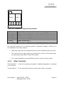
1.1 Keypad
Figure 1: Keypad of the VoIP-Telephone
Short Manual
ResistTel IP2 / IP152
ExResistTel IP2 / IP154
Page 5
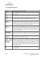
1.2 Keypad Description
Symbol
Description and Key Functions
The Loudspeaker key is used to control the hands free and
listening mode.
The Menu key is used to open the main menu or to save changes.
The Disconnect key is used to terminate calls or any menu.
(short)
(long)
The Enquiry key is used to enable the "Hold" and "Switch"
functions. In idle mode, the Enquiry key is used to call up the list
of missed calls. To execute the enquiry function the Enquiry key
has to be pressed short (shorter than 0.5 seconds).
The Redial key is used to select the list of 100 phone numbers last
dialled. In the menu, the redial key confirms the current selection.
The phone ResistTel IP2 / IP152 has no single Redial key. To
execute the redial function the Redial key has to be pressed long
(longer than a second).
Arrow keys are used for navigation in the menu and browsing in
the telephone directory. The volume can only be adjusted during a
call.
(long)
...
The asterisk key also serves as a mute key. During a call, a longer
press switches the microphone off or on.
Digit keys for entering phone numbers. The asterisk and hash
keys have special functions. To enter asterisk and Hash the keys
have to be pressed short (shorter than 0.5 seconds). To enter
Mute (asterisk) and Shift (hash) the keys have to be pressed long
(longer than a second). After pressing of shift the digit keys (1 – 9
and 0) become function keys. After executing a function key the
shift mode is ended.
The Clearing key is used in input mode to delete the characters
left to the cursor.
Page 6
Short Manual
ResistTel IP2 / IP152
ExResistTel IP2 / IP154
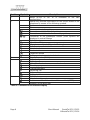
Symbol
Description and Key Functions
(long)
The headset key is used to make and to end a call in the headset
mode. The phone ResistTel IP2 / IP152 has no single headset key.
To execute the headset key function the key
has to be pressed
long (longer than a second) and then the loudspeaker key
has
to be pressed. The headset key can be used only, if the headset is
configured to on (see manual). This makes sense only, if a
headset is connected to the phone.
Table 1: Keys and Function Elements
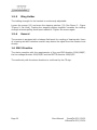
1.3 Display
The display of the VoIP Telephone ResistTel IP2 / IP152 has 7 lines with max. 30
characters and a state line for showing information.
1.3.1
Default Display
The name and telephone number of the current registration is displayed in the first
line.
The middle lines display special information relating to the condition.
The date, time and registration status is displayed in the last line.
1
Torsten
4 2
3
5
72
06.04.10 14:40
Figure 2: Default Display of the VoIP Telephone ResistTel IP2 / IP152
Short Manual
ResistTel IP2 / IP152
ExResistTel IP2 / IP154
Page 7
Position
1
Description
Name (H.323 or SIP ID or nickname of the PBX
configuration)
2
Status line; provides information on the current status of the
telephone by means of the following symbols.
06.04.10 Date
14:00
Time
No connection to the gatekeeper
Connection established to the gatekeeper
Connection established to the secondary gatekeeper
Connection to the gatekeeper broken. (Both symbols are
displayed in mutual change
Open listening
Hands free Mode
Microphone switched off (symbol flashing)
Call diversion activated
Handset activate
Headset active
Telephone locked
Calling number transmission locked
3
Own call number (E.164)
Called party
4
Calling party
Unknown number/name, unresolved number
Diverting party
Transferring party
Returning call
Call pending
Call on hold
5
Shift Mode
Headset configured
Audio connection of the active call is scrambled (SRTP)
0:12
Duration of the active call
Table 2: Contents of the Default Display
Page 8
Symbol
Short Manual
ResistTel IP2 / IP152
ExResistTel IP2 / IP154
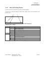
1.3.2
Menu and Listing Display
The first six lines are used for the menu and listing display.
The last line is used for display of menu level, display name, scroll information and
type of entry.
1 2
3
5 display name
Figure 3: Menu and Listing Display of the VoIP Telephone
ResistTel IP2 / IP152
Position
1
Symbol
Description
Menu or listing level 0
<
Menu or listing level 1
+
Menu or listing level 2
5
Menu or listing level 3
Menu or listing level 4 or lower
2
Display name
3
Scrolling up possible
Scrolling up and down possible
Scrolling down possible
a
Alphanumerical input
1
Numerical input
Choice, next level
Table 3: Contents of the Menu and Listing Display
Short Manual
ResistTel IP2 / IP152
ExResistTel IP2 / IP154
Page 9
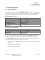
1.4 As-Delivered Condition
The phone is available for delivery in different versions.
• Handset with armed court.
• Single LAN connection or switch LAN modul with two LAN connections with
internal connection and cable screw connection or external LAN connection
and plug in connection.
• Housing in black or coloured in red or blue.
• Some Sealing plugs to connect option equipment
• Optional: max. 5 cable screw caps
• Optional: relay module
Accessories (optional):
− Headset with connection cable and attachment of the bracket.
− LAN connector from Phoenix Contact, consisting of:
o RJ sleeve housing Type VS-08-T-RJ45/IP67, Art.-Nr.: 1688696
o Male insert RJ45, CAT5, 8-polig Type VS-08-ST-RJ45/IP67, order-no.:
1688573
− LAN female connector for cable mounting from Tycoelectronics (AMP), orderno. 116604-2
− Cable screw cap
− Sealing plugs
2 keys for torx socket screws TX20, TX30
1.4.1
•
•
Default Version one LAN Connection with a Cable Screw
Cap
1 LAN connection internal
Housing with 1 cable screw caps and 2 bored holes with sealing plugs at the
upper side.
Box contents
The scope of the delivery includes:
- Telephone
- Printed short manual
- Manual on CD
- 1 LAN female connector for cable mounting from Tycoelectronics (AMP),
order-no. 116604-2
- 2 keys for torx socket screws TX20, TX30
1.4.2
•
•
•
Version one LAN Connection with a Female Housing
Connection
1 LAN connection female housing connection
1 LAN connection (without LAN interface) and sealing plug at the housing
Housing with 1 bored hole with sealing plug at the upper side
Page 10
Short Manual
ResistTel IP2 / IP152
ExResistTel IP2 / IP154
Box contents
The scope of the delivery includes:
- Telephone
- Printed short manual
- Manual on CD
- 1 LAN connector from Phoenix Contact, consisting of:
o RJ sleeve housing Type VS-08-T-RJ45/IP67, Art.-Nr.: 1688696
o Male insert RJ45, CAT5, 8-polig Type VS-08-ST-RJ45/IP67, order-no.:
1688573
- 2 keys for torx socket screws TX20, TX30
1.4.3
•
•
Version one Switch LAN Module
Connections with Cable Screw Cap
with
two
LAN
2 LAN connections internal
Housing with 1 cable screw caps and 2 bored holes with sealing plugs at the
upper side.
Box contents
The scope of the delivery includes:
- Telephone
- Printed short manual
- Manual on CD
- 1 LAN female connector for cable mounting from Tycoelectronics (AMP),
order-no. 116604-2
- 2 keys for torx socket screws TX20, TX30
1.4.4
•
•
•
Version one Switch LAN Module
Connections with Cable Screw Cap
with
two
LAN
1 LAN connection female housing connection
1 LAN connection and sealing plug at the housing
Housing with 1 bored hole with sealing plug at the upper side
Box contents
The scope of the delivery includes:
- Telephone
- Printed short manual
- Manual on CD
- 1 LAN connector from Phoenix Contact, consisting of:
o RJ sleeve housing Type VS-08-T-RJ45/IP67, Art.-Nr.: 1688696
o Male insert RJ45, CAT5, 8-polig Type VS-08-ST-RJ45/IP67, order-no.:
1688573
- 2 keys for torx socket screws TX20, TX30
Short Manual
ResistTel IP2 / IP152
ExResistTel IP2 / IP154
Page 11
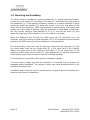
1.5 Mounting and Installing
The device must be installed on a plane surface only, in vertical operating position.
Loosen the cover screws (2) (see Figure 5 to Figure 7) and detach the upper part of
the telephone (1). If the optional accessory headset or a second earpiece is being
employed, attach the bracket (10) using two screws (11) to the rear panel of the
lower part of the telephone. (With the accessories named before, the bracket and
screws are in the scope of delivery. With all accessories a cable gland is delivered.)
Put four screws, having a head diameter of 10 to 13 mm into the holes (20) and
attach the lower part of the telephone (3) to the wall or to a holder.
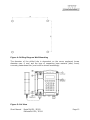
Guide the telephone wire through the cable screw cap (4) and place it on the
terminals. Only wires having a sheath diameter of 5 to 9 mm should be used because
otherwise the IP66 housing protection standard is not guaranteed.
Prior to assembly, check cover seal for tightness. Using the plug connector (7), plug
the ribbon cable onto the pin contact strip (8) in the upper part of the housing.
Attach the upper part of the telephone and fasten it to the lower part of the
telephone with the four cover screws (2). Upon disassembly of optional accessories,
suited sealing plugs must be used to close the resulting openings.
In this telephone connected cords may have hazardous voltages.
To ensure that no water gets into the enclosure it is essential that no gaskets are
damaged during installation. The ingress of water can cause accessible parts of the
telephone to become live.
Installation and connection must be carried out by competent personnel familiar with
electrical and network installations.
Page 12
Short Manual
ResistTel IP2 / IP152
ExResistTel IP2 / IP154
Figure 4: Drilling Diagram Wall Mounting
The diameter of the drilled hole is dependent on the screw employed (screw
diameter max. 8 mm) and the type of supporting base material (steel, wood,
concrete, plasterboard etc.) and must be chosen accordingly.
Figure 5: Set View
Short Manual
ResistTel IP2 / IP152
ExResistTel IP2 / IP154
Page 13
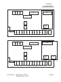
Figure 6: Inside View of Telephone upper Part
Figure 7: Inside View of Telephone lower Part
Page 14
Short Manual
ResistTel IP2 / IP152
ExResistTel IP2 / IP154
X5
X1 X2 X3 X4
X6
X7
X
8
X
1
0
LAN
PoE
X
9
X11
1
2
3
4
5
6
7
8
9
10
11
12
X
1
2
13
Figure 8: Connection Diagram with Single LAN Module
X6
X5
X1 X2 X3 X4
X7
X
8
X
1
0
LAN1
PoE
X
9
X11
1
2
3
4
5
6
7
8
9
10
11
12
13
LAN2
X
1
2
Figure 9: Connection Diagram with Switch LAN Module
Short Manual
ResistTel IP2 / IP152
ExResistTel IP2 / IP154
Page 15
Connector
description
X1
Loudspeaker left
X2
Loudspeaker right
X3
Heater of the Display
X4
Illumination of the Display
X5
Display
X6
LAN Module
X7
Keypad
X8
Hookswitch (Reed Contact)
X9
RS232 Module (optional)
X10
Amplifier Module (optional)
X11
Handset
X12
Relay Module (optional)
LAN PoE
LAN with PoE (LAN-Link, single LAN Module)
LAN1 PoE
LAN1 with PoE (LAN-Link, Switch LAN Module)
LAN2 (PC)
LAN2 (PC-Link, Switch LAN Module)
1 - 13
Terminals (Configuration see the following Chapters)
Table 4: Plug in Connectors and Terminals of the ResistTel IP2 / IP152
1.5.1
1.5.1.1
LAN-Connections
Default Version one LAN Connection with a Cable
Screw Cap
The telephone has in the default version one internal LAN-connection with a cable
screw cap. For the connection a LAN cable must be pulled through the cable screw
cap. Inside the phone the female LAN connection from Tycoelectronics (AMP) has to
be pressed on the cable (Refer to chapter 1.4 beginning on page 10). A female LAN
cable connector belongs to the as-delivered condition. With the inside the phone
existing little LAN connection cable, the LAN can be connected with the phone.
The LAN delivery can be available with PoE (Power over Ethernet). Alternatively the
phone can be supplied with power external.
All not used cable feed through have to be closed with sealing plugs.
1.5.1.2
Version one LAN Connection with a Female Housing
Connection
The phone has in this version one LAN-connection with a female LAN connection at
the housing. LAN-cable, used for plug into the telephone ResistTel IP2 / IP152, have
to be adapted with a connector from Phoenix contact (Refer to chapter 1.4 beginning
on page 10), to preserve the IP66 degree of protection. A LAN cable connector
belongs to the as-delivered condition.
Page 16
Short Manual
ResistTel IP2 / IP152
ExResistTel IP2 / IP154
The LAN-lead wire has to be connected to the connector in the front. Die LAN lead
wire can to be with PoE (Power over Ethernet). Alternatively the phone can be
supplied with power external.
The second LAN connector of the ResistTel IP2 / IP152 is a blind connector closed
with a protective cap to preserve the IP66 degree of protection
All not used cable feed through have to be closed with sealing plugs.
Caution
You can use PoE (Power over Ethernet) or an external connection to supply the
ResistTel IP2 / IP152 with power.
Don’t use both at the same time, to prevent damage to the equipment.
1.5.1.3
Version with Switch LAN Module with two LAN
Connections with Cable Screw Caps
The telephone has in this version two internal LAN-connections with a cable screw
cap. For the connection the LAN cable must be pulled through the cable screw cap.
Inside the phone the female LAN connection from Tycoelectronics (AMP) has to be
pressed on the cable (Refer to chapter 1.4 beginning on page 10). A female LAN
cable connector belongs to the as-delivered condition. With the inside the phone
existing little LAN connection cable, the LAN can be connected with the phone.
The LAN1 delivery can be available with PoE (Power over Ethernet). Alternatively the
phone can be supplied with power external.
The LAN2 delivery doesn’t support PoE. Also it can’t be used to connect a phone
directly, which should be powered with PoE.
All not used cable feed through have to be closed with sealing plugs.
1.5.1.4
Version with Switch LAN Module with two LAN
Connections with two Female Housing Connections
The phone has in this version two LAN-connections with a female LAN connection at
the housing. LAN-cable, used for plug into the telephone ResistTel IP2 / IP152, have
to be adapted with a connector from Phoenix contact (Refer to chapter 1.4 beginning
on page 10), to preserve the IP66 degree of protection. A LAN cable connector
belongs to the as-delivered condition.
Short Manual
ResistTel IP2 / IP152
ExResistTel IP2 / IP154
Page 17
The LAN-lead wire has to be connected to the connector in the front. Die LAN1 lead
wire can to be with PoE (Power over Ethernet). Alternatively the phone can be
supplied with power external.
The second LAN connector of the ResistTel IP2 / IP152 doesn’t support PoE. Also it
can’t be used to connect a phone directly, which should be powered with PoE.
All not used cable feed through have to be closed with sealing plugs.
1.5.2
External Power Supply Connection
An external power supply can be adapted to the terminals 5 (+) and 6 (-). The
voltage has to be:
Without using the optional voltaic separated inputs: 15 V – 57 V DC, 13 W
With using the optional voltaic separated inputs: 21,5 V – 57 V DC, 13 W
If the external power connection will be used, you must not use PoE at the LAN
connection.
1.5.3
Relay Connection
The phone can be build up with a relay module with two relays with a single
changeover switch optional.
The maximal breaking capacity of a relay is depending on the voltage:
•
240 V, 6 A, AC
•
24 V, 6 A, DC
•
32 V, 5 A, DC
•
48 V, 1 A, DC
Page 18
Short Manual
ResistTel IP2 / IP152
ExResistTel IP2 / IP154
K1
Relay 1
1
Relay 2
2 3 1 2 3
Figure 10: Connection Diagram Relay Module
Connector
Description
K1
Cable to the main board (connection to plug in X12)
1 (relay 1)
Bottom contact relay 1
2 (relay 1)
Middle contact relay 1
3 (relay 1)
Switching contact relay 1
1 (relay 2)
Bottom contact relay 2
2 (relay 2)
Middle contact relay 2
3 (relay 2)
Switching contact relay 2
Table 5: Plug in Connectors and Terminals of the Relay Module
Pay particular attention to the following points if hazardous voltages (>48V) are to
be connected to the relay outputs:
•
Cable and cords must be insulated and have to be conducted below the cover.
•
The circuits that the relay outputs are connected to must be of the same type;
i.e. both mains, both SELV or both TNV circuits.
•
It is not permissible to connect different types of circuits to these relays.
1.5.4
Other Terminals
The terminals 1 – 4 are for connecting a headset. A detailed description is enclosed
in the manual.
The terminals 7 – 13 are reserved for future use and must not be connected.
Short Manual
ResistTel IP2 / IP152
ExResistTel IP2 / IP154
Page 19
1.5.5
Sling Holder
The holding strength for the handset is continuously adjustable.
Loosen the screws (12) and move the stopping catches (13) (See Figure 5 – Figure
7Figure 5: Set View). Pushing the stopping catches together increases the holding
strength whereas pulling them apart reduces it. Tighten the screws again.
1.5.6
General
The receiver is equipped with a leakage field spool for coupling of hearing aids. Users
of a hearing aid with inductive receiver may receive the signal from the receiver inset
directly.
1.6 EMC-Directive
The device complies with the requirements of the new EMC-directive 2004/108/EC,
the low voltage directive 2006/95/EC and the R&TTE directive 1999/5/EC.
The conformity with the above directives is confirmed by the CE sign.
Page 20
Short Manual
ResistTel IP2 / IP152
ExResistTel IP2 / IP154
2 Operating Manual
2.1 Operating Basics
The keys below the display (
) of the VoIP telephone
ResistTel IP2 / IP152 serve menu navigation and, for edit field input purposes, are
assigned an additional function on top of their actual function, as explained below.
Key assignment in menu:
The function …
scrolling upwards
scrolling downwards
one level up without saving
one level down
one level up with saving
Leave
the
menu
complete
immediately
… is performed by …
Arrow key up
Arrow key down
Arrow key left
Arrow key right
Menu key
Disconnect key
Key assignment in edit field:
The function …
scrolling right
scrolling left
Delete character in front of cursor
… is performed by …
Arrow key right
Arrow key left
Clearing key
Pressing and holding the numeric key, activates the character mode. Refer to
chapter 2.1.4 Input of Characters and Special Characters beginning on page 23.
The initial condition means that the telephone is in the switching state hang up.
This state consists if the following conditions are fulfilled:
a) The telephone is hanged up or will be hanged off and then the key
pressed.
will be
b) The hands free mode isn’t active.
c) The headset mode isn’t active.
Short Manual
ResistTel IP2 / IP152
ExResistTel IP2 / IP154
Page 21
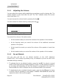
2.1.1
Adjusting the Volume
You can adjust the volume while establishing connections as well as during calls. The
volume remains on this level after the call. The "Vol." indicator shows the current
value (see Figure 11).
You can increase the volume level by pressing the key
You can reduce the volume level by pressing the key
.
.
72
73
Martin
vol. 06.04.10 14:40
0:22
Figure 11: Adjusting the Volume
You control the volume of the active mode.
•
At the handset mode you control the volume of the speaker of the handset.
•
At the listening mode you control the volume of the additional connected
speaker of the phone.
•
At the hands free mode you control the volume of the speaker in hands free
mode.
•
At the headset mode you control the volume of the speaker of the headset.
2.1.2
Do not Disturb
You can turn off the do not disturb function of the VoIP telephone
ResistTel IP2 / IP152 simply by pressing a key, for example if you do not wish to be
disturbed during a meeting.
1. To activate the do not disturb function; press the key
for about a second
whilst in idle mode until the display appears in Figure 12. The telephone reacts to
an incoming call depending on how this feature is configured at the time. For
further details on how to configure the do not disturb feature (see manual).
2. To deactivate the do not disturb function again; press the key
again for about
a second until the signalling in the display is deleted. Afterwards the device will
respond to calls in the usual way again.
Page 22
Short Manual
ResistTel IP2 / IP152
ExResistTel IP2 / IP154
Torsten
72
06.01.10 14:40
Figure 12: Do not Disturb
2.1.3
Different Types of Call Numbers
In addition to normal call numbers, your IP telephone can also dial H.323 names and
IP addresses.
Call numbers consisting of characters other than the digits 0 to 9 and the characters
* and # are considered to be H.323 names. Call numbers beginning with the
character @ are always regarded as H.323 names. The @ is removed before dialling
however.
2.1.4
Input of Characters and Special Characters
You can enter any Western European characters in accordance with ISO 8859-1
using the keypad. The assignment of the characters and special characters to the
keys can be seen in Table 6.
The letter mode is activated by pressing the respective key pad for an extended
moment of time. Subsequently, it is possible to switch between the letters by
pressing the key several times in short intervals or by keeping the key pressed.
key
possible characters and special characters
1
1 + ( ) , - & @ # “ * ! $ % . / : ; < = > ? ' [ ] \ ^ _ `{ | } ~ £ § ¿ ÷
2
2abcABCäàáâãåæçÄÀÂÃÁÅÆÇ
3
3defDEFèéêëÈÉÊË
4
4ghiGHIìíîïÌÍÎÏ
5
5jklJKL
6
6mnoMNOöñòóôõøÑÒÓÔÕ
7
7pqrsPQRSß
8
8tuvTUVüùúûÜÙÚÛ
9
9wxyzWXYZýÝÿ
0
0 (space character)
*
*
#
#
Table 6: Input of Characters and Special Characters
Short Manual
ResistTel IP2 / IP152
ExResistTel IP2 / IP154
Page 23
2.2 Operating Modes
The phone ResistTel IP2 / IP152 allows making calls in different operating modes.
1. Handset mode
At handset mode the call will be operated with the handset.
2. Handset mode with open listening
At handset mode with open listening the call will be operated with the
handset. The hands free speaker of the phone will be connected additionally.
Persons present in the room can listen to the call.
3. Hands free mode
At hands free mode the call will be operated with the hands free microphone
and hands free speaker of the phone. All persons present in the room can
take part to the call.
If a headset is connected and configured:
4. Headset mode
At headset mode the call will be operated with the headset.
5. Headset mode with open listening
At headset mode with open listening the call will be operated with the
headset. The hands free speaker of the phone will be connected additionally.
Persons present in the room can listen to the call.
The already active operating mode will be displayed in the state line of the phone.
2.2.1
Changeover from Handset Mode to Handset Mode with
Open Listening
To change from handset mode to handset mode with open listening, you have to
press the loudspeaker key
during a call.
Page 24
Short Manual
ResistTel IP2 / IP152
ExResistTel IP2 / IP154
2.2.2
Changeover from Handset Mode with Open Listening to
Handset Mode
To change from handset mode with open listening to handset mode, you have to
press the loudspeaker key
during a call.
2.2.3
Changeover from Handset Mode (with or without Open
Listening) to Hands Free Mode
To change from handset mode (with or without open listening) to hands free mode,
you have to press the loudspeaker key
and hang up the handset with pressed
loudspeaker key . Afterwards the loudspeaker key
can be released.
2.2.4
Changeover from Handset Mode (with or without Open
Listening) to Headset Mode
To change from handset mode (with or without open listening) to headset mode, you
have to press the headset key (Key
long (longer than a second) and then the
loudspeaker key ). Afterwards the handset can be hanged up.
2.2.5
Changeover from Hands Free Mode to Handset Mode
To change from hands free mode to handset mode, you have to lift off the handset.
2.2.6
Changeover from Hands Free Mode to Headset Mode
To change from hands free mode to headset mode, you have to press the headset
key (Key
long (longer than a second) and then the loudspeaker key ).
2.2.7
Changeover from Headset Mode to Headset Mode with
Open Listening
To change from headset mode to headset mode with open listening, you have to
press the loudspeaker key
during a call.
2.2.8
Changeover from Headset Mode with Open Listening to
Headset Mode
To change from headset mode with open listening to headset mode, you have to
press the loudspeaker key
during a call.
Short Manual
ResistTel IP2 / IP152
ExResistTel IP2 / IP154
Page 25
2.2.9
Changeover from Headset Mode (with or without Open
Listening) to Handset Mode
To change from headset mode (with or without open listening) to handset mode, you
have to lift off the handset.
2.2.10 Other Changeover of the Operating Mode
Other changes of the operating mode can’t take place directly. They are only possible
with one of the above listed intermediate steps indirect.
2.3 Call Functions
2.3.1
Answering Calls
You receive a call and your phone rings. The name or phone number of the caller is
displayed. The name or phone number of the person for whom the call is intended is
also displayed. This is particularly useful in the event of multiple registrations on your
telephone in order to identify the actual caller when a call is diverted to your
telephone.
Torsten
Martin
73
06.01.10 14:40
Figure 13: Answering a Call
72
0:22
Answering or rejecting calls:
If you would like to answer the call, you have different possibilities:
•
Lift the handset.
•
Press the loudspeaker key
•
Press the headset key (Key
loudspeaker key ).
.
long (longer than a second) and then the
You will be connected to the caller.
Page 26
Short Manual
ResistTel IP2 / IP152
ExResistTel IP2 / IP154
To reject the call, press the key
will hear an engaged tone.
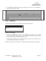
2.3.2
. The phone returns to the idle state and the caller
Terminating a Call
To finish a call respectively to the active operating mode:
•
Put the handset back on its rest
•
Press the key
•
Press the loudspeaker key
•
Press the headset key (Key
loudspeaker key ).
2.3.3
.
.
long (longer than a second) and then the
Making Calls
To call someone, you can use single or block dialling.
2.3.3.1
Single Dialling
For single dialling take the following steps:
Torsten
0211654321
72
Please dial
06.01.10 14:40
Figure 14: Direct Dialling
0:00
1. Respectively to the wanted calling mode:
•
Pick up the handset (handset mode).
•
Press the loudspeaker key
•
Press the headset key (Key
long (longer than a second) and then the
loudspeaker key ) (headset mode).
(hands free mode).
2. Enter the phone number. In this case the VoIP telephone dials the number while
it is being entered.
Short Manual
ResistTel IP2 / IP152
ExResistTel IP2 / IP154
Page 27
3. To finish a call respectively to the active operating mode:
•
Put the handset back on its rest (handset mode).
•
Press the key
•
Press the loudspeaker key
•
Press the headset key (Key
long (longer than a second) and then the
loudspeaker key ) (headset mode).
2.3.3.2
(All modes).
(hands free mode).
Block Dialling
For block dialling do the following steps:
1. Let the handset on its rest and don’t activate the hands free or headset mode.
2. Enter the phone number completely.
3. When entering the telephone number, you may edit already entered digits. Use
the
and
keys to move the cursor, and the key
to delete the digit to the
left of the cursor.
4. Respectively to the wanted calling mode, you can setup the call as follows. In this
matter, it will be dialled after one of the following activities.
a. Lift off the handset (handset mode).
b. Press the loudspeaker key
(hands free mode).
c. Press the headset key (Key
long (longer than a second) and then the
loudspeaker key ) (headset mode).
d. Press the key
or key
(short or long). With a configured headset
you will reach the headset mode otherwise the hands free mode.
e. Using the key
(short or long) executes the selection immediately.
Using the key , however, executes the selection only if the cursor is
situated to the right of the last entered digit.
5. When using block dialling, you may enter further properties of the selection. Do
so by pressing the
key. See chapter 2.3.3.2.1 on page 29.
Page 28
Short Manual
ResistTel IP2 / IP152
ExResistTel IP2 / IP154
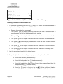
2.3.3.2.1 Menu Parameter Input Indirect Dialling
The following is displayed:
Call as User..................
Save no. in Directory
Send Message
Dial..........................
Number Present.:
On
+ Indirect dialling
Figure 15: Menu Parameter Input Indirect Dialling
•
If you use the cursor keys to select the menu item Call as User and then press
the key , the menu User List appears (see manual). Now the User can be
changed prior to dialling. The change affects the current call only.
•
If you use the cursor keys to select the menu item Save no. in Directory and
then press the key , the menu Directory Input appears (see manual). Here
the entry may be edited and used in the telephone book.
•
If you use the cursor keys to select the menu item Dial and then press the key
, the current telephone number is dialled immediately.
•
If you use the cursor keys to select the menu item Number Present. and then
press the key , the number presentation is switched. The change affects the
current call only.
•
If you press the key
(long), the current telephone number is dialled
immediately, regardless of the menu item currently selected.
•
With Number Presentation On/Off you can select, weather the own calling
number or name will be displayed at the called subscriber.
2.3.3.3
Dialling during existing Connections
During existing connections all entered digits (0 – 9, *, #) are transmitted as DTMF
signals. Using this DTMF procedure it is possible to access menu-controlled services
(e. g. answering machines, voice boxes) directly via the telephone keypad.
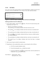
2.3.4
Redialling
Up to 100 of the last numbers dialled are saved automatically, together with the time
and date, and can be dialled again.
Short Manual
ResistTel IP2 / IP152
ExResistTel IP2 / IP154
Page 29
01 06.02.10 11:30
Martin 73
02 06.02.10 11:30
Thomas 70
03 06.03.10 11:29
Peter 36
< Calls (outbound)
Figure 16: List of Recently Dialled Numbers and Sent Messages
Dialling numbers from the redial list
1. In the initial condition, press the key
displayed (see Figure 16).
(long). The list of numbers dialled last is
•
Success (connected/not connected).
The symbol
on the display indicates that there has been a successful call. A
not connected call will be displayed without a symbol.
•
The symbol
on the display indicates that there has been a redirected call.
•
The symbol
on the display indicates that there has been a transferred call.
•
The symbol
on the display indicates that there has been a dialled number
on a locked telephone.
•
The symbol
on the display indicates that there has been an automatic call.
•
The symbol
on the display indicates that there has been a message sent.
2. Use the arrow keys to select the desired entry.
3. Respectively to the wanted calling mode, you can setup the call as follows:
a. Lift off the handset (handset mode).
b. Press the loudspeaker key
(hands free mode).
c. Press the headset key (Key
long (longer than a second) and then the
loudspeaker key ) (headset mode).
d. Press key
(short or long) or the key . With a configured headset
you will reach the headset mode otherwise the hands free mode.
Page 30
Short Manual
ResistTel IP2 / IP152
ExResistTel IP2 / IP154
2.3.5
Call Back
Up to 100 of the last incoming calls are saved automatically, together with the time
and date, and can be called back, if the number of the caller was transmitted.
01 06.02.10 11:30
Martin 73
02 06.02.10 11:30
Thomas 70
03 06.03.10 11:29
Peter 36
> Calls (inbound)
Figure 17: List of the Last Incoming Calls and Received Messages
Dialling numbers from the calling list
1. In the initial condition, press the key
is displayed (see Figure 17).
(short). The list of the last incoming calls
•
Success (connected/not connected).
The symbol
on the display indicates that there has been a call.
•
The symbol
on the display indicates that there has been a redirected call.
•
The symbol
on the display indicates that there has been a transferred call.
•
The symbol
on the display indicates that there has been a dialled number
on a locked telephone.
•
The symbol
•
The symbol
received.
on the display indicates that there has been an automatic call.
on the display indicates that there has been a message
2. Use the arrow keys to select the desired entry.
3. Respectively to the wanted calling mode, you can setup the call as follows:
a. Lift off the handset (handset mode).
b. Press the loudspeaker key
(hands free mode).
c. Press the headset key (Key
long (longer than a second) and then the
loudspeaker key ) (headset mode).
Short Manual
ResistTel IP2 / IP152
ExResistTel IP2 / IP154
Page 31
(short or long) or the key . With a configured headset
d. Press key
you will reach the headset mode otherwise the hands free mode.
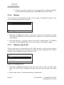
2.3.6
Muting
You can mute the microphone during a call to make a confidential enquiry in the
room without being heard on the phone.
Torsten
Thomas
72
77
06.01.10
Figure 18: Muting
14:40
0:22
1. Press the key
during a call for more than a second. The microphone symbol
" " flashes (see Figure 18). The microphone is switched off. You can now make a
room enquiry.
2. Press the Mute key
microphone symbol
2.3.7
during a call for more than a second again. The flashing
disappears and the microphone is switched on again.
Making second Call
The line can be put on hold during a call. With the call on hold, you can make a
second call to someone else. The person on hold can't hear the second call. The hold
function is also needed to switch or transfer a call.
Torsten
Peter
Torsten
Please dial
06.01.10 14:40
Figure 19: Holding a Call
72
36
72
0:22
1. Press the key
(short) during a call. The call is put on hold. you hear a dial
tone. The line on hold is displayed normally, the active line inversely (see Figure
19).
2. Dial the call number. A further connection is established.
Page 32
Short Manual
ResistTel IP2 / IP152
ExResistTel IP2 / IP154
3. To terminate the enquiry call, press the key
partner previously put on hold.
. You return to the conversation
Tip
The call with the conversation partner highlighted on the display (active) is
terminated by pressing the key . If you alternatively want to terminate a call with
another conversation partner, first select the respective conversation partner whose
connection you want to disconnect using the arrow keys and only then press the
key .
2.3.8
Switching
You can switch between two connections using the switch function.
Torsten
Peter
Torsten
Thomas
72
36
72
70
06.01.10 14:40
Figure 20: Switching
0:22
1. Press the key
(short) two times or the key
(short) followed by the key
during a call with an active line and a line on hold. The active line is put on hold
and the line on hold is activated (see Figure 20).
2. To terminate the active line, you must press the key
active conversation partner is terminated.
. The connection to the
Please note also the tip in chapter 2.3.7 "Making second Call" beginning on page 32.
Short Manual
ResistTel IP2 / IP152
ExResistTel IP2 / IP154
Page 33
2.3.9
Transferring a Call
You are making a call and would like to transfer it to another party.
Torsten
Peter
Torsten
Thomas
72
36
72
70
06.01.10 14:40
0:22
Figure 21: Transferring a Call
1. Press the key
(short) during a call.
The call is put on hold. You hear a dial tone. The line on hold is displayed
normally and the active line inversely.
2. Dial the call number of your choice.
The connection is established. If the called party answers, this can be treated like
a second call, as above.
3. To connect the caller will be connected with the dialled number you have the
following possbilities:
a. Put the handset back on its rest (handset mode).
b. Press the loudspeaker key
(hands free mode).
c. Press the headset key (Key
long (longer than a second) and then the
loudspeaker key ) (headset mode).
d. Press the key
(short) followed by the key
connected with the dialled number.
. The caller will be
Tip
When transferring a call, you do not have to wait until the desired subscriber
answers. You can hang up immediately after dialling the phone number.
Page 34
Short Manual
ResistTel IP2 / IP152
ExResistTel IP2 / IP154
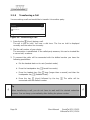
2.3.10 Transferring a Call directly
You are making a call and want to switch it to another connection.
Torsten
Peter
72
36
Transfer
1
Figure 22: Transferring a Call Directly
1. Press the key
(long) during a call.
2. You will be left. The actual connection will not be displayed.
3. Dial the call number of your choice.
4. Press the key
(short) or key
.
5. The caller will be connected with the dialled port directly.
6. With handset mode hang up.
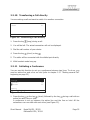
2.3.11 Initiating a Conference
You can use this function to set up a conference between two lines. To do so, you
need an active line and a line on hold (refer to chapter 2.3.7 "Making second Call"
beginning on page 32).
Torsten
anonym
Torsten
Peter
72
72
36
3party
06.01.10 14:40
Figure 23: Conference
0:22
1. Press the key
or the key
(short) followed by the key
during a call with an
active line and a line on hold.
A conference is set up between the active line and the line on hold. All the
subscribers can now talk with each other (see Figure 23).
Short Manual
ResistTel IP2 / IP152
ExResistTel IP2 / IP154
Page 35
respective the key
(short)
2. You can end the conference by pressing the key
followed by the key
or twice the key
(short). If you end the conference with
pressing the key
or the key
(short) followed by the key , the call put on
hold prior to the initiated conference is now on hold again and the previously
active call is active once again. If you end the conference with pressing the key
(short) twice, the call put on hold prior to the initiated conference is now
active and the previously active call is now on hold.
3. To terminate the active line, you must press the key . The connection to the
active conversation partner is terminated. Please note also the tip in chapter
2.3.7.
Note
If you
•
hang up (handset mode)
•
press the loudspeaker key (hands free mode)
•
press the headset key (Key
long (longer than a second) and then the
loudspeaker key ) (headset mode)
during the conference, the lines of both parties keep connected.
Page 36
Short Manual
ResistTel IP2 / IP152
ExResistTel IP2 / IP154
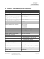
3 Technical Data weatherproof Telephones
Connection data
Power supply
Power over Ethernet refer to IEEE 802.3af
or external power supply
48V DC (Min. 44V, Max. 57V)
Class 0
15 V – 57 V DC
Voltage PoE
PoE
Voltage external power supply without
using the optional voltaic separated
inputs
Voltage external power supply for using 21.5 V – 57 V DC
the optional voltaic separated inputs
Power
12.95 W
Breaking capacity relay (optional)
240 V, 6 A, AC
24 V, 6 A, DC
32 V, 5 A, DC
48 V, 1 A, DC
Connection
RJ45 Port (10/100 Mbit/s)
Ringing volume
Max. 98 dB(A) in 1 m distance
Housing (Height x Width x Depth)
without cable screw caps
Weight (default version)
Display
267 x 225 x 132 mm
Keypad
Hook switch
Operating utilization position
Handset
Mouthpiece
Receiver inset
Electret-foil microphone
Dynamic receiver inset with magnetic field
generator
Integrated adjustable sling holder
Armed court
Sling holder
Handset cable
Short Manual
ca. 5.0 kg
• 182 x 64 pixel
• Field of view ca. 78 mm x 26 mm
• Metal keypad with ice protection
• 21 keys with ABC marking
Reed contact without mechanical switch
Vertical wall mounting
ResistTel IP2 / IP152
ExResistTel IP2 / IP154
Page 37
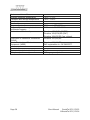
Environmental conditions
Ambient operating temperature
Transport and storage temperature
Conformities
Degree of protection
Degree of protection against external
mechanical impacts
Declaration of Conformity
Restriction of Hazardous Substances
(ROHS)
Waste Electrical and Electronic
Equipment (WEEE)
User interface
Web-interface (administration)
Telephone (user menu)
Page 38
-40°C…+70°C
-40°C…+80°C
IP66 acc. to IEC 60529
IK09 acc. to EN IEC 62262
Directive
Directive
Directive
Directive
1999/5/EU (R&TTE)
2004/108/EG (EMC)
2006/95/EG (low voltage)
2011/65/EG
Directive 2012/19/EG
EAR registration no.: DE 58023377
English
16 languages adjustable
Short Manual
ResistTel IP2 / IP152
ExResistTel IP2 / IP154
4 Notes
Short Manual
ResistTel IP2 / IP152
ExResistTel IP2 / IP154
Page 39
Subject to alterations
or errors
FHF Funke + Huster Fernsig GmbH
Gewerbeallee 15-19 · D-45478 Mülheim an der Ruhr
Phone +49 / 208 / 82 68-0 · Fax +49 / 208 / 82 68-286
http://www.fhf.de · e-mail: [email protected]