1
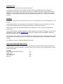
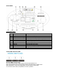
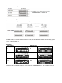
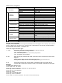
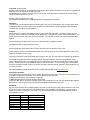
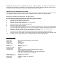
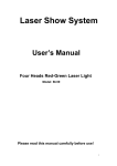
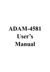
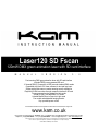
Laser120 SD Fscan
120mW DMX green animation laser with SD card interface
M
A
N
U
A
L
V
E
R
S
I
O
N
3
.
0
Fast scanning DMX green animation laser with SD card interface
Includes FREE pre-programmed SD card
10 channel DMX 512 operation via SD-ram and standard DMX modes
Compatible with Kam LC01 laser software for text and logo input
25kpps optical fast scanner creates amazing smooth animations
Playback of ILDA laser show through computer interface & SD card
Pre-programmed moving patterns in Auto mode
Sound-to-Light, Auto and DMX 512 modes
Linkable Master/Slave in Sound-to-Light mode
Fan cooled and adjustable hanging bracket
Key operated power control
For the latest instruction manual updates and information on the entire Kam range visit:
www.kam.co.uk
Kam products are manufactured by: Lamba plc, Unit 1, Southfields Road, Dunstable, Bedfordshire, United Kingdom LU6 3EJ
Telephone: (+44) (0)1582 690600 • Fax: (+44) (0)1582 690400 • Email: [email protected] • Web: www.lambaplc.com
If this product is ever no longer functional please take it to a recycling plant for environmentally friendly disposal.
Due to continuous product development, specifications and appearance are subject to change.
© COPYRIGHT LAMBA plc 2009. E&O E.
INTRODUCTION
Thank you for purchasing the Kam Laser120 SD Fscan.
To optimise the performance of this product, please read these operating instructions carefully to
familiarize yourself with the basic operations of this unit. The KAM Laser120 SD Fscan laser has been
designed to create amazing laser effects. Please keep these user instructions in a safe place for future
reference. This unit has been tested at the factory before being shipped to you. There is no assembly
required.
WARNING
To prevent or reduce the risk of electrical shock or fire, do not expose this unit to high temperature, rain or
moisture.
Unintended reflections of the laser beam from reflective or metallic surfaces can be dangerous. Do not
touch the laser aperture. When cleaning the laser Aperture, please use a soft cloth.
Never remove warning or informative labels from the equipment. Do not connect this equipment to a
dimmer-pack.
Laser Class 3B product. National regulations must be adhered to at all steps of installation. These can be
downloaded from the website www.kam.co.uk (In Germany apply DIN 56912 and BGVR LASER note:
additional regulations may apply).
Always replace the fuse with exact same type because anything other than the specified fuse can cause a
fire, electric shock, damage your unit, and will void your manufactures warranty. This appliance must be
earthed.
This appliance should be used by qualified personnel only.
UNPACKING YOUR NEW KAM PRODUCT
Carefully inspect your Laser, as you unpack it. If any damage is evident, please notify the supplier you
purchased the unit from immediately. For safety reasons do not use the unit if any damage has occurred
during transportation.
Contents:
Laser 120 SD FScan laser projector
Power cable
DMX signal cable
User manual
SD card
1pc
1pc
1pc
1pc
1pc
REAR PANEL
FUNCTION TABLE
1
2
3
4
5
6
7
8
9
10
11
12
13
MIC
VOLUME
Message center
SD Card Control Settings
SD Card Slot
Mode Switches
DMX IN
DMX OUT
Dip Switches
ILDA IN
ILDA THRU
ON/OFF
AC IN and Fuse
Audio in
Volume sensitivity
Indicating the state of SD card controlling system
Used to set some important parameters for SD card
SD Card (maximum capacity of 3 Gigabytes)
Select the operating modes
DMX 512 signal input
DMX 512 signal output
Setting the DMX start address
ILDA standard signal input
ILDA standard signal through
Safety key switch
AC 110-240V 50/60Hz
OPERATING INSTRUCTIONS
Sound & DMX Control mode
You can choose Sound or DMX control mode through dipswitch 10.
When all dipswitches are set to the OFF position, the unit works in sound mode.
When dipswitch 1 is set to the ON position, the unit works in auto mode.
To set unit to slave mode, set dipswitch 2 to the on position.
Function mode setting
For DMX, switch 10 must be on
Master/Slave Settings, No DMX Controller
For master/slave mode, put the 2nd switch to ON position and it works as slave.
DMX Control mode
For DMX mode, the 10th dip switch must be ON. Then, set the DMX base address with the binary system
“0” or “1” through switch 1-9
Examples:
DMX address
DMX address
1
33
97
113
161
225
The device has 10 operating channels. If you set the first on DMX address “1”, the next DMX device can
follow at address 20.
DMX channels assignment
Channel
DMX512 VALUE
0-49
50-99
1.Control Mode
100-199
200-255
0-15
16-25
2.Blanking
26-135
& Blackout
136-245
F
246-255
I
R 3.Pattern
0-255
S
0-127
T 4. Vertical Move
128-191 (Ch1 must be 200-255)
192-255 (Ch1 must be 200-255)
P
0-127
A 5. Horizontal Move
128-191 (Ch1 must be 200-255)
T
192-255 (Ch1 must be 200-255)
T
0-127
E 6. Vertical Roll
128-255 (Ch1 must be 200-255)
R
0-127
N 7. Horizontal Roll
128-255 (Ch1 must be 200-255)
0-127
G
R
128-191 (Ch1 must be 200-255)
8.Rotation
O
192-255 (Ch1 must be 200-255)
U
P
0-85
9.Zoom In & Out
86-170
171-255
10.Point Draw
0-255
FUNCTION
Sound control (3-10ch not available)
Auto mode (3-10ch not available)
DMX control
Auto mode
Blackout
No Blanking
Flow water effect
Shimmer effect
Immovable blanking
124 patterns
Manual vertical move
Auto down, speed up rate
Auto up, speed up rate
Manual horizontal
Manual right, speed up rate
Manual left, speed up rate
Manual vertical rotation
Auto vertical rotation, speed up rate
Manual horizontal rotation
Auto horizontal rotation
Manual rotation
Auto clockwise rotation, speed up rate
Auto anti-clockwise rotation, speed up
rate
From small to large, speed up rate
From large to small, speed up rate
Large – small – large, speed up rate
0 Full size, 1-255 small to large
SD Card Controlling Mode
The panel can be used to access some important parameters for the ILDA projector. If the memory of the panel is
empty, it displays “Err” at power-on. At normal function, if parameters are set correctly, the panel displays
the actual DMX base address, for example “001”.
There are 3 keys from left to right:
1. FUNC
By pressing FUNC, the actual parameter for changing is selected.
There are 3 parameters currently available:
“Adr” = DMX base address
“Int” = max. Intensity for colour- and intensity output laser
“Ort” = orientation of the projection
2. SEL
After selecting the parameter with FUNC, press SEL and the current stored value will be
displayed.
By pressing SEL again, the digit for changing will blink.
Pressing select multiple times will activate all digits by blinking one after the other.
3. Up
Use this key to change the current number in the blinking digit. The number will be
increased. When reaching the maximum number (9), the number will be start from zero again.
Example:
Set DMX base address to 200.
Press “FUNC” until “Adr” blinks
Press “SEL” until current value is displayed and right digit blinks
Press “Up” until “0” is reached.
Press “SEL” to go to middle digit
Press “Up” until “0”.
Press “SEL” until left digit blinks
Press “Up” until “2” is reached.
Press “FUNC” for exit this parameter. The value is stored automatically.
All values are stored and activated when exit the parameter input by pressing “FUNC parameter. The
value is stored automatically. After not changing anything in the parameter input routine, the panel will
return to main routine after about 10 seconds without storing value to memory.
Note that playback of longer shows may be interrupted (stopped) when changing parameters at the panel
during show output. Display of single frames of short sequences normally will not be interrupted.
Limits
DMX base address 1 – 512
Intensity 0 – 99
Orientation 0 – 7
Limits will be controlled automatically by the panel. If trying to set a value beyond the limits, the panel
automatically corrects to an allowed value during input.
Intensity
The value under “Int” sets the maximum intensity for the laser.
All show values for RGB-outputs and analog intensity will be divided by this value linear.
For the projector, this value should be set to 99.
Orientation
There are 8 different values possible, allowing all possible projection orientations.
This is important for back projections or if it is not clear how the projector is installed at the location.
0: normal
1: X invert
2: Y invert
3: X and Y invert
4: X and Y changed
5: X and Y changed and X invert
6: X and Y changed and Y invert
7: X and Y changed and both inverted
Message center
If any error condition occurs, a code will be displayed on the status-LEDs (see table). Not all errors will cause a
stop of playback. Errors from the memory card (read/write) will cause a total shutdown of the player. If there is
no card or the card is not inserted correctly of if there is no right format or file system, the player functions
will be shut down. When there is no file allocated to a selected show number, this is no error condition and
the player will switch the output to Pause (Shown umber 0 PAUSE). When the accessed show file is not
valid or corrupted, the playback will be switched off. All other functions keep running and the selection of
another show is possible.
Ready
Yellow
Yellow
Yellow
Yellow
DMX
Green
Data
Yellow
Yellow
Yellow
Yellow
-
Error
Red
Red
X
-
No MMC/SD-card
File system FAT16 not found
Data error when reading MMC/SD-card
File not found or invalid file
No DMX-signal
Ready
DMX channels assignment
Channel1: Show select L
This channel is used for show selection; one of the first 16 shows (including Pause) can be selected.
Channel2: Show select H
16 banks of shows, 16 shows each, 256 shows can be selected using this function.
Channel3: Size (projection size)
When you change size by the use of DMX-control, a fader position of 0 (minimum) can cause a single
point laser beam. This can be a dangerous condition!
DMX only allows a refresh rate of 50 Hz.
Moving a control fader fast will result in jumps of the display settings.
Channel4: Offset X (horizontal position)
A value of zero results in the maximum negative offset.
128 is the center position and 255 is the maximum positive offset.
When changing this value via DMX, the projected display can jump, because DMX signal rate is too slow.
Channel5: Offset Y (vertical position) See Offset X.
Channel6: Frame repeat
Shows in ILDA-format do not contain any timing information. When all frames of a show are outputted one
after the other, the animation speed is too fast.
By repeating every frame a number of times, the speed of the animation movement can be controlled.
Values by DMX-control are 1 to 16.
Memory card (Compact Flash card)
All Compact Flash cards up to a maximum capacity of 3 Gigabytes can be used.
Important
The card has to be formatted with FAT16 file system only. We recommend the use of high quality cards.
Unbranded cards can cause read errors. All cards shipped together with the equipment are formatted
correctly and must NOT be reformatted.
Caution
When using own cards or reformatted cards by using a PC with Windows** operating system, it is not
ensured, that the cards are formatted FAT16. Depending on the memory size of the card, Windows** can
format these to FAT12, FAT16 or FAT32 file system. The Unit will not work with other file systems than
FAT16.
Avoid formatting the card by the use of a PC with Windows** operating system!
No subdirectories are supported by the unit.
All show files and configuration files must be placed in the root directory of the card.
There must not be more than 260 files located in the root directory. It is recommended not to store more
files than necessary on the card.
Only short filenames will be processed (8.3-format) by the unit. The unit does not support long filenames.
The name of the files should be not longer than 8 characters plus the extension (for example ILDA).
When copying files to the card, both long and short filenames are created. The unit only reads the short
names. The long names need additional space in the root directory. To avoid losing space (and limiting
maximum possible number of files), the names should be kept as short as possible. Short filenames are
not case sensitive!
WE RECOMMEND USING THE KAM LCO1 LASER SOFTWARE. See www.kam.co.uk
Reserved Filenames
Some filenames are reserved for device control. These files will be read out by the unit automatically and
must NOT be deleted or renamed. The following filenames are reserved:
CONFIG.DAT Contains output settings for the unit.
FLASHMP.BIN Controls program for firmware update.
FWUP12C.BIN File for a specific firmware update. When this file is found, the unit automatically updates
the firmware. After this procedure, this file will be deleted automatically by the unit
PC MODE
Put the mode switches to PC MODE position and then connect the PC ILDA output interface to the ILDA
IN connector on the rear panel using a standard and easily available (not supplied), ILDA connecting
cable. If you want to make your own cable, you should comply with the below signal definition table of
ILDA-DB-25F pinouts.
Signal name
X+
Y+
Green+
XYGreenGround
Pin
1
2
3
14
15
16
25
Notes
-5 to +5V
-5 to +5V
0V to 2.5V
Connect to ground
Connect to ground
Connect to ground
Cable shield
Caution: Because the device is equipped with scanner motors of 20Kpps, you should do tune down the
setting of scan rate below 20K points per second when using software (Pangolin, Mamba, Phoenix etc) to
control the device. Too high scan rate will be greatly harmful to the scanner,
IMPORTANT INFO REGARDING SD CARDS
Your Kam SD laser requires the SD card to be formatted in FAT16 to allow files to be recognised. FAT16
(File Allocation Table) is a filing system used in computer memory systems and storage cards.
Required for formatting; SD card reader, SD card and a PC.
Please follow the instructions below to format your SD card in FAT16.
1.
Insert the SD card into the card reader
2.
Right click on the Windows „Start‟ button.
3.
Click once on the „Explore‟ option.
4.
Find the SD card in the Folders section of the window.
5.
Right-click once on the SanDisk (SD) card icon.
6.
Click once on the „Format‟ option.
7.
Change the file system to FAT16 on the “File system” drop-down menu. If your file system options
do not include FAT16 specifically, use „FAT‟ or „FAT (Default)‟. Both are synonymous with FAT16.
8.
Adjust the „Allocation unit size‟ using the drop-down menu if necessary. The default FAT16
allocation unit size is 16 KB, but you can change it up to 32 KB.
9.
Click once on the „Start‟ button on the Format window after making any desired changes.
Click once on the „Yes‟ button on the warning pop-up window to start formatting the SanDisk card.
10.
Click once on the „Close‟ button on the Format window to complete the process.
SPECIFICATIONS
Laser type:
Laser class:
Laser life:
Cooling ways:
Colour:
Laser output:
Scanner system:
Optical angle:
Control mode:
Power supply:
Power consumption:
Dimensions:
Net Weight:
Diode Pumped Solid Stated Laser (DPSSL)
Class IV
>5000 Hours
Air-cooled.
Green
120mW@532nmW
25Kpps
±20°
Sound active/Auto mode with simultaneous operation
USITT DMX512 (10channels)
Playback of ILDA laser show files in SD card (6channels)
ILDA 25-pin Interface for PC controller
AC 110-240V 50/60Hz
<300W
W200mm ×H260 mm ×D300 mm
6.0Kg