1
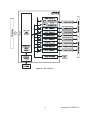
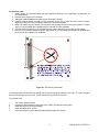
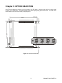
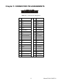
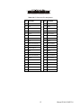
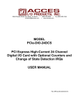
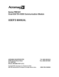
10623 Roselle Street, San Diego, CA 92121 y (858) 550-9559 y Fax (858) 550-7322
[email protected] y www.accesio.com
MODEL P104-COM232-8
USER MANUAL
FILE: mP104-COM232-8.A1g
Notice
The information in this document is provided for reference only. ACCES does not assume any liability arising
out of the application or use of the information or products described herein. This document may contain or
reference information and products protected by copyrights or patents and does not convey any license under
the patent rights of ACCES, nor the rights of others.
IBM PC, PC/XT, and PC/AT are registered trademarks of the International Business Machines Corporation.
Printed in USA. Copyright 2003, 2007 by ACCES I/O Products, Inc. 10623 Roselle Street, San Diego, CA
92121. All rights reserved.
WARNING!!
ALWAYS CONNECT AND DISCONNECT YOUR FIELD CABLING WITH
THE COMPUTER POWER OFF. ALWAYS TURN COMPUTER POWER
OFF BEFORE INSTALLING A BOARD, CONNECTING AND
DISCONNECTING CABLES, OR INSTALLING BOARDS INTO A SYSTEM
WITH THE COMPUTER OR FIELD POWER ON MAY CAUSE DAMAGE TO
THE I/O BOARD AND WILL VOID ALL WARRANTIES, IMPLIED OR
EXPRESSED.
2
Manual P104-COM232-8
Warranty
Prior to shipment, ACCES equipment is thoroughly inspected and tested to applicable specifications. However,
should equipment failure occur, ACCES assures its customers that prompt service and support will be available.
All equipment originally manufactured by ACCES which is found to be defective will be repaired or replaced
subject to the following considerations.
Terms and Conditions
If a unit is suspected of failure, contact ACCES' Customer Service department. Be prepared to give the unit
model number, serial number, and a description of the failure symptom(s). We may suggest some simple tests
to confirm the failure. We will assign a Return Material Authorization (RMA) number which must appear on the
outer label of the return package. All units/components should be properly packed for handling and returned
with freight prepaid to the ACCES designated Service Center, and will be returned to the customer's/user's site
freight prepaid and invoiced.
Coverage
First Three Years: Returned unit/part will be repaired and/or replaced at ACCES option with no charge for labor
or parts not excluded by warranty. Warranty commences with equipment shipment.
Following Years: Throughout your equipment's lifetime, ACCES stands ready to provide on-site or in-plant
service at reasonable rates similar to those of other manufacturers in the industry.
Equipment Not Manufactured by ACCES
Equipment provided but not manufactured by ACCES is warranted and will be repaired according to the terms
and conditions of the respective equipment manufacturer's warranty.
General
Under this Warranty, liability of ACCES is limited to replacing, repairing or issuing credit (at ACCES discretion)
for any products which are proved to be defective during the warranty period. In no case is ACCES liable for
consequential or special damage arriving from use or misuse of our product. The customer is responsible for all
charges caused by modifications or additions to ACCES equipment not approved in writing by ACCES or, if in
ACCES opinion the equipment has been subjected to abnormal use. "Abnormal use" for purposes of this
warranty is defined as any use to which the equipment is exposed other than that use specified or intended as
evidenced by purchase or sales representation. Other than the above, no other warranty, expressed or implied,
shall apply to any and all such equipment furnished or sold by ACCES.
3
Manual P104-COM232-8
Table of Contents
Chapter 1: INTRODUCTION ..................................................................................................5
Figure 1-1: Block Diagram...............................................................................................6
Chapter 2: INSTALLATION....................................................................................................7
Figure 2-1: PC/104 Key Information ................................................................................8
Chapter 3: OPTION SELECTION...........................................................................................9
Figure 3-1: Option Selection Map ....................................................................................9
Chapter 4: ADDRESS SELECTION .....................................................................................10
Chapter 5: CONNECTOR PIN ASSIGNMENTS...................................................................11
Table 5-1: P1 Connector Pin Assignment ......................................................................11
Table 5-2: P2 Connector Pin Assignment ......................................................................12
Chapter 6: SPECIFICATIONS..............................................................................................13
4
Manual P104-COM232-8
Chapter 1: INTRODUCTION
This communications card interfaces to the CPU through a 33MHz 32bit PCI (Peripheral Component
Interconnect, specification revision 2.3) local bus. While it is technically a PC/104-plus card, the ISA bus
connector does not connect to any circuit.
!
High Performance Octal PCI UART
!
16550 Compatible Register Set
!
Up to 460Kb/s Serial Data Rate
!
Global Interrupt Source Register
!
Data Transfer in Byte, Word, and Double-Word
!
64-Byte Transmit and Receive FIFOs per each of eight UARTs
!
Transmit and Receive FIFO Level Counters
!
Programmable Transmit and Receive FIFO Trigger Level
This card is an eight channel RS-232 communication instrument. Based on the XR17D158, the card has
eight enhanced 16550 UARTs, each with a set of modem signals (CTS, RTS, RI, DTR, DSR CD). A
460Kb/s is guaranteed for all channels with up to 3K Ohm 1000pF loads. All interrupts may be monitored
at a 32-bit status register. Each UART has both a 64 byte transmit and a 64 byte receive FIFO.
The typical quiescent current draw from the user's 5V supply is less than 50mA (with P1 and P2
disconnected). If every transmitter line is loaded with 3K Ohm, current draw should still be less than
150mA.
Linux drivers and sample programs are supplied with the card.
The provided Windows drivers are 100% compatible with the normal Microsoft-provided Serial Application
Programming Interface. This means every program you've ever used with a standard serial port in
Windows will also work with these ports, no problem. In addition, we provide several utility and sample
programs to help you write your own code, if you're not using something off-the-shelf.
5
Manual P104-COM232-8
Figure 1-1: Block Diagram
6
Manual P104-COM232-8
Chapter 2: INSTALLATION
A printed Quick-Start Guide (QSG) is packed with the board for your convenience. If you’ve already performed
the steps from the QSG, you may find this chapter to be redundant and may skip forward to begin developing
your application.
The software provided with this PC/104 Board is on CD and must be installed onto your hard disk prior to use.
To do this, perform the following steps as appropriate for your operating system. Substitute the appropriate drive
letter for your CD-ROM where you see d: in the examples below.
CD Installation
The following instructions assume the CD-ROM drive is drive “D”. Please substitute the appropriate drive letter
for your system as necessary.
DOS
1.
2.
3.
4.
Place the CD into your CD-ROM drive.
Type B-to change the active drive to the CD-ROM drive.
Type GLQR?JJ- to run the install program.
Follow the on-screen prompts to install the software for this board.
WINDOWS
1.
Place the CD into your CD-ROM drive.
2.
The system should automatically run the install program. If the install program does not run promptly,
click START | RUN and type BGLQR?JJ, click OK or press -.
3.
Follow the on-screen prompts to install the software for this board.
LINUX
1.
Please refer to linux.htm on the CD-ROM for information on installing under linux.
Installing the Hardware
Before installing the board, please run setup.exe. The SETUP Program can be used to assist in configuring the
two switches on the board. The setup program does not set the options on the board, these must be set
manually by the user.
The PCI bus clock trace length from the CPU to the cards in the stack is tuned so that the clock edge arrives at
the interface when data is valid. Since boards in the PC/104 stack are at different distances from the CPU,
provision is made on the CPU board to supply four clock signals with compensating trace lengths. Two signals
from other groups must be likewise selected: IDSEL and INT. When the PCI bus is being initialized, the
operating system will enable each card with a hard-wired select line and read it's configuration registers. An
address is assigned, space in the memory map and I/O map is reserved, etc. Similarly, the CPU's interrupt
controller resources (INTA, INTB, INTC, INTD) will be distributed among the cards in the stack. A set of four-toone multiplexers and two slide switches are used to select which PCI clock, IDSEL and INT lines are routed to
the card’s PCI bus interface.
Only four PCI boards are allowed in a PC/104-Plus stack, each board must get a specific set of signals. These
signals are selected with two slide switches, labeled SEL-1 and SEL-2, which form a binary value to control the
mux (SEL-1 is the least significant bit and SEL-2 is the most significant bit). If this card is furthest from the CPU,
slide both switches to the OFF STATE. This will select the signal with the longest trace on the CPU board
(signal group 3). If this card is closest to the CPU, slide both switches to the ON STATE. This will select the
signal with the shortest trace on the CPU board (signal group 0). Place the SEL-1 switch to ON and SEL-2 to
OFF to select signal group 2, place the SEL-1 switch to OFF and SEL-2 to OFF to select signal group 1.
7
Manual P104-COM232-8
To Install the Card
1. Install jumpers for selected options and base address according to your application requirements, as
mentioned above.
2. Remove power from the PC/104 stack.
3. Assemble standoff hardware for stacking and securing the boards.
4. Carefully plug the board onto the PC/104 connector on the CPU or onto the stack, ensuring proper
alignment of the pins before completely seating the connectors together.
5. Install I/O cables onto the board’s I/O connectors and proceed to secure the stack together or repeat
steps 3-5 until all boards are installed using the selected mounting hardware.
6. Check that all connections in your PC/104 stack are correct and secure then power up the system.
7. Run one of the provided sample programs appropriate for your operating system that was installed from
the CD to test and validate your installation.
Figure 2-1: PC/104 Key Information
Our setup program will lead the user through the process of setting the options on the card. The setup program
does not set the options on the card. These must be set by jumpers on the card.
To install the card:
1.
2.
3.
4.
5.
Turn off the computer power.
Position the slide switches to select the clock, IDSEL, and interrupt signal group.
Install the card in a PC/104-Plus stack.
Install I/O cables at P1 and P2.
Inspect for proper fit of the card and cable and then tighten the screws.
8
Manual P104-COM232-8
Chapter 3: OPTION SELECTION
Most PCI bus signals are common to all four cards in the PCI stack. However, there are four unique signal
groups, one for each card. The slide switches select which signal group goes to each card. The card in the
stack closest to the CPU board must get signal group 0.
Figure 3-1: Option Selection Map
9
Manual P104-COM232-8
Chapter 4: ADDRESS SELECTION
The system BIOS or operating system will assign the address. The card occupies 4K bytes of I/O space. The
32 bit interrupt status register is at base address + 80h.
PCI architecture is Plug-and-Play. This means that the BIOS or Operating System determines the resources
assigned to PCI cards rather than you selecting those resources with switches or jumpers. As a result, you
cannot set or change the card's base address. You can only determine what the system has assigned.
To determine the base address that has been assigned, run the PCIFind.EXE, or PCINT utility program
provided. This utility will display a list of all of the cards detected on the PCI bus, the addresses assigned to
each function on each of the cards, and the respective IRQs (if any) allotted.
Alternatively, some operating systems (Windows 95/98/2000) can be queried to determine which resources
were assigned. In these operating systems, you can use either PCIFind (DOS), PCINT (Windows95/98/NT), or
the Device Manager utility from the System Applet of the control panel. The card is installed in the Data
Acquisition class of the Device Manager list. Selecting the card, clicking Properties, and then selecting the
Resources Tab will display a list of the resources allocated to the card.
The PCI bus supports 64K of I/O space. Your card's addresses may be located anywhere in the 0000 to FFFF
hex range.
PCIFind uses the Vendor ID and Device ID to search for your card, then reads the base address and IRQ.
If you want to determine the base address and IRQ yourself, use the following information.
The Vendor ID for the card is 494F. (ASCII for "IO")
The Device ID for the card is 10A8.
10
Manual P104-COM232-8
Chapter 5: CONNECTOR PIN ASSIGNMENTS
Table 5-1: P1 Connector Pin Assignment
Pin
Function
Pin
Function
1
Carrier Detect 0
2
Data Set Ready 0
3
Rx 0
4
RTS 0
5
Tx 0
6
CTS 0
7
Data Terminal Ready 0
8
Ring Indicator 0
9
ground
10
no connection
11
Carrier Detect 1
12
Data Set Ready 1
13
Rx 1
14
RTS 1
15
Tx 1
16
CTS 1
17
Data Terminal Ready 1
18
Ring Indicator 1
19
ground
20
no connection
21
Carrier Detect 2
22
Data Set Ready 2
23
Rx 2
24
RTS 2
25
Tx 2
26
CTS 2
27
Data Terminal Ready 2
28
Ring Indicator 2
29
ground
30
no connection
31
Carrier Detect 3
32
Data Set Ready 3
33
Rx 3
34
RTS 3
35
Tx 3
36
CTS 3
37
Data Terminal Ready 3
38
Ring Indicator 3
39
ground
40
no connection
11
Manual P104-COM232-8
Table 5-2: P2 Connector Pin Assignment
Pin
Function
Pin
Function
1
Carrier Detect 4
2
Data Set Ready 4
3
Rx 4
4
RTS 4
5
Tx 4
6
CTS 4
7
Data Terminal Ready 4
8
Ring Indicator 4
9
ground
10
no connection
11
Carrier Detect 5
12
Data Set Ready 5
13
Rx 5
14
RTS 5
15
Tx 5
16
CTS 5
17
Data Terminal Ready 5
18
Ring Indicator 5
19
ground
20
no connection
21
Carrier Detect 6
22
Data Set Ready 6
23
Rx 6
24
RTS 6
25
Tx 6
26
CTS 6
27
Data Terminal Ready 6
28
Ring Indicator 6
29
ground
30
no connection
31
Carrier Detect 7
32
Data Set Ready 7
33
Rx 7
34
RTS 7
35
Tx 7
36
CTS 7
37
Data Terminal Ready 7
38
Ring Indicator 7
39
ground
40
no connection
12
Manual P104-COM232-8
Chapter 6: SPECIFICATIONS
Specification
PCI Bus:
PC/104 Bus:
I/O Space:
Rev. 2.3
Feedthrough only, no connection to the card
Requires 4k
16550 Compatible
Data Size:
5, 6, 7 or 8 bits
Stop bit length:
1, 1.5 or 2 bits
Parity:
Odd, even, none, forced to 1, or forced to 0
Break condition:
On or off
Maximum Baud Rate:
460.8Kb/s (transceiver limit with full load)
Full Duplex Operation
Eight 64 Byte Transmit FIFO, 64 Byte Receive FIFO (16C550 FIFO = 16 Bytes)
S/W programmable FIFO trigger levels (16C550 trigger levels are fixed)
12 standard registers for UART monitoring and control plus special registers
Loop-back mode
Scratch pad register
Transceiver I/O Characteristics
Receiver Input Resistance:
Receiver Input Sensitivity:
Receiver Input Voltage Range:
Driver Slew Rate:
Driver Load Impedance:
Driver Output Signal Level:
3K to 7K ohm
±3V
±15V
30V/FS
3K to 7K ohm
Loaded ±5V
Unloaded ±15V
Transceiver ESD Characteristics:
±15KV Human Body Model
±15KV Air Discharge
±8KV Contact Discharge
Communications Interface:
Eight channels split between two 40 pin male headers
Meets or exceeds the IEEE RS-232 standard
Environmental
Operating Temperature Range:
Humidity:
Storage Temperature Range:
Power Required:
Size:
-40 C to +85 C
5% to 95%, non-condensing
-65 C to +125 C
50mA quiescent, 150mA maximum
PC/104-Plus format, 3.5" x 3.75"
13
Manual P104-COM232-8
Customer Comments
If you experience any problems with this manual or just want to give us some feedback, please email us
at: [email protected]. Please detail any errors you find and include your mailing address so that
we can send you any manual updates.
10623 Roselle Street, San Diego CA 92121
Tel. (858)550-9559 FAX (858)550-7322
www.accesio.com
14
Manual P104-COM232-8