1
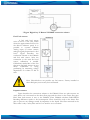
Socratec Telematic GmbH
Fleetview-XMT
System-Manual
We reserve all rights in this document and in the information contained therein. Reproduction, use or disclosure to third parties without express
authority is forbidden. © 2011 Socratec Telematic GmbH.
Guido Hollenstein
SY-11-002(SystemManual-XMT).db.odt
Page 1/27
Contents
1
INTRODUCTION
1.1
1.2
1.3
1.4
2
BASIC DESCRIPTION
2.1
2.2
2.3
2.4
3
ATTENTION
INSTRUCTIONS OF SAFETY
LEGAL NOTICE
ABOUT DOCUMENT
PACKAGE CONTENTS
ADDITIONAL ACCESSORIES
BASIC CHARACTERISTICS
MECHANICAL FEATURES
CONNECTION, PINOUT, ACCESSORIES
3.1
3.2
3.3
3.4
3.5
LED STATUS
SOCKET 2X10
PORT1/NMEA
AUDIO
ACCESSORIES
5
5
5
6
6
7
7
7
7
9
12
12
13
16
16
16
4
FIRMWARE
21
5
OPERATIONAL BASICS
23
5.1
5.2
5.3
5.4
5.5
5.6
5.7
5.8
6
OPERATIONAL PRINCIPALS
SLEEP MODE
ACCELEROMETER
VIRTUAL ODOMETER
VOICE FUNCTIONALITY
PROFILES
PROFILE SWITCH DEPENDING ON GSM OPERATOR CODE
PROFILE SWITCH DEPENDING ON I/O EVENT
CONFIGURATION
6.1
CONFIGURATOR
6.2
GLOBAL PARAMETER SETTINGS
6.3
TEMPERATURE SENSORS
6.4
SYSTEM SETTINGS
6.5
GPS SETTINGS
6.6
GEOFENCE SETTINGS
6.7
GSM SETTINGS
6.8
GPRS SETTINGS
6.9
SMS SETTINGS
6.10
SEND PARAMETER SETTINGS
6.11
ACCELEROMETER
6.12
I/O SETTINGS
6.12.1 Monitoring
6.12.2 Event Generating
6.13
CAN SETTINGS
7
SMS COMMAND LIST
7.1
7.2
7.3
7.4
7.5
7.6
7.7
7.8
7.9
7.10
7.11
GETSTATUS
GETWEEKTIME
GETOPS
GETCFGTIME
GETGPS
LOADPROFILE#
GETVER
GETSTACK
GETIO
GETINFO
READIO #
23
23
23
24
24
24
25
26
27
27
30
30
31
32
33
35
35
35
36
37
37
40
40
42
47
49
49
49
49
50
50
50
50
50
51
51
2
7.12
7.13
7.14
7.15
8
SETDIGOUT ####
GETPARAM ####
SETPARAM #### #
FLUSH #,#,#,#,#,#,#
PARAMETER LIST
8.1
PARAMETERS VALUE TYPES
8.2
GLOBAL PARAMETERS
8.2.1
Profile switch (ID=100)
8.2.2
Microphone level (ID=101)
8.2.3
Speaker level (ID=102)
8.2.4
Call number (ID 103)
8.2.5
Call trigger (ID 104)
8.2.6
Record search (ID 105)
8.3
DATA ACQUISITION AND SENDING PARAMETERS
8.3.1
Time based acquire interval (ID=11)
8.3.2
Distance based acquire interval (ID=12)
8.3.3
Angle based coordinate acquisition (ID=13)
8.3.4
Data Send interval (ID=270)
8.3.5
Minimum records number in packet (ID=232)
8.3.6
GPRS Enable (ID=240)
8.3.7
GSM Operator list (ID=271)
8.3.8
GPRS Data send week time schedule (ID=272)
8.3.9
SMS Data send week time schedule (ID=273)
8.3.10 Schedule parameter format:
8.3.11 SMS Data send allow (ID=250)
8.3.12 SMS Send Timeout (ID=251)
8.3.13 24 Records time step (ID=274)
8.4
SMS SETTINGS AND PARAMETERS
8.4.1
SMS User login (ID=252)
8.4.2
SMS User password (ID=253)
8.4.3
Server Number (ID=260)
8.4.4
Authorized Number #1 (ID=261)
8.5
GPRS ACCESS AND ADDRESS SETTINGS
8.5.1
APN Name (ID=242)
8.5.2
APN username (ID=243)
8.5.3
APN Password (ID=244)
8.5.4
Data send protocol (ID=231)
8.5.5
Server IP address (ID=245)
8.5.6
Server port number (ID=246)
8.6
GEOFENCE ZONES SETTINGS AND PARAMETERS
8.6.1
GeoFence border width (ID=20)
8.6.2
GeoFence Zone #1 Configuration Parameter (ID=30)
8.6.3
GeoFence x1 (ID=31)
8.6.4
GeoFence y1 (ID=32)
8.6.5
GeoFence x2 (ID=33)
8.6.6
GeoFence y2 (ID=34)
8.6.7
All the rest zones
8.7
SYSTEM PARAMETERS
8.7.1
Voice Call Auto Answer after rings (ID=230)
8.7.2
Device Power mode (ID=0)
8.7.3
GPS Enable (ID=10)
8.7.4
Profile name (ID=710)
8.7.5
Sleep mode (ID=000)
8.8
IO PROPERTIES
8.8.1
IO#0 property parameter (ID=300)
8.8.2
IO#0 priority (ID=301)
8.8.3
IO#0 High level (ID=302)
8.8.4
IO#0 Low level (ID=303)
8.8.5
IO#0 logic operand (ID=304)
51
51
52
52
53
53
53
53
53
53
53
54
54
54
54
54
54
55
55
55
55
56
56
56
56
56
57
57
57
57
57
57
58
58
58
58
58
58
58
59
59
59
59
60
60
60
60
61
61
61
61
61
62
62
62
62
62
63
63
3
8.8.6
IO#0 averaging length (ID=305)
8.9
CAN (FMS) INTERFACE PARAMETERS
8.9.1
CAN Baud Rate (ID=600)
8.9.2
CAN#0 Element Id type (ID=610)
8.9.3
CAN#0 Data mask (ID=611)
8.9.4
CAN#0 Identifier ID (ID=612)
8.9.5
CAN#0 Identifier Mask ID (ID=613)
8.10
ACCELEROMETER PARAMETERS
8.10.1 Delta X (ID=281)
8.10.2 Delta Y (ID=282)
8.10.3 Delta Y (ID=283)
8.10.4 Start timeout (ID=284)
8.10.5 Stop timeout (ID=285)
63
64
64
64
64
65
65
65
65
66
66
66
66
9
DEBUG MODE
67
10
MOUNTING RECOMMENDATIONS
68
10.1
10.2
10.3
10.4
10.5
10.6
11
CONNECTING WIRES
CONNECTING POWER SOURCE
CONNECTING IGNITION WIRE
CONNECTING GROUND WIRE
CONNECTING ANTENNAS
MODULE INSTALLATION
CHANGE LOG
68
68
68
68
68
69
70
4
1 INTRODUCTION
1.1
Attention
Do not disassemble the device. If the device is damaged,
the power supply cables are not isolated or the isolation is
damaged, before unplugging the power supply, do not
touch the device.
All wireless data transferring devices produce interference
that may affect other devices which are placed nearby.
The device may be connected only by qualified personnel.
The device must be firmly fastened in the predefined
location.
The programming must be performed using a second class
PC (with autonomic power supply).
The device is susceptible to water and humidity.
Warning! If wrong accumulator is used, the device may
explode!
Any installation and/or handling during a lightning storm
is prohibited.
Please use cables provided with FM4100 device.
Teltonika is not responsible for any harm caused by using
wrong cables for PC <-> FM4100 connection.
1.2
Instructions of safety
This chapter contains information on how to operate FM2200 safely. By following
these requirements and recommendations, you will avoid dangerous situations. You must
read these instructions carefully and follow them strictly before operating the device!
The device uses a 10V...30V DC power supply. The nominal voltage is 24V DC. The
allowed range of voltage is 10V...30V DC, power – not more than 12 W.
To avoid mechanical damage, it is advised to transport the FM4100 device in an
impact-proof package. Before usage, the device should be placed so that its LED indicators
are visible, which show the status of operation the device is in.
5
When connecting the connection (2x10) cables to the vehicle, the appropriate jumpers of the
power supply of the vehicle should be disconnected.
Before dismounting the device from the vehicle, the 1x6 connection must be
disconnected.
The device is designed to be mounted in a zone of limited access, which is inaccessible
for the operator. All related devices must meet the requirements of standard EN 60950-1.
The device FM4100 is not designed as a navigational device for boats.
1.3
Legal Notice
Copyright © 2008 Teltonika. All rights reserved. Reproduction, transfer, distribution
or storage of part or all of the contents in this document in any form without the prior
written permission of Teltonika is prohibited.
Other products and company names mentioned here may be trademarks or trade
names of their respective owners.
1.4
About document
This document contains information about the architecture, possibilities, mechanical
characteristics, and configuration of the FM2200 device.
Acronyms and terms used in document
• PC – Personal Computer.
• GPRS – General Packet Radio Service.
• GPS – Global Positioning System.
• GSM – Global System for Mobile Communications.
• SMS – Short Message Service.
• AC/DC – Alternating Current/Direct Current.
• Record – AVL data stored in FM4100 memory. AVL data contains GPS and I/O
information
• AVL packet - Data packet that is being sent to server during data transmission. AVL
packet contains from 1 to 25 records.
6
2 BASIC DESCRIPTION
FM4100 is a terminal with GPS and GSM connectivity, which is able to determine the
object’s coordinates and transfer them via the GSM network. This device is perfectly suitable
for applications where location acquirement of remote objects is needed. It is important to
mention that FM4100 has additional inputs and outputs, which let you control and monitor
other devices on remote objects. 1-Wire® interface (for Dallas digital thermometer or IButton reader) and CAN interface integrated (for trucks FMS interface data acquisition). It
also has a RS232 port for NMEA output and configuration (also it could be used for
peripheral devices communication with special firmware).
2.1
Package contents
The FM4100 device is supplied to the customer in a cardboard box containing all the
equipment that is necessary for operation. The package contains:
1. The FM4100 device.
2. Input and output power supply cable with a 2x10 connection.
3. GPS and GSM antennas.
4. Port ½ and Port 3 cables
5.
2.2 Additional accessories
There are two accessories available for FM4 that are not included in the package:
1. Temperature sensor TTJ-101
2. iButton
Note: the manufacturer does not supply a SIM card in the package, which is necessary for connection to the
GSM network! SIM card can be obtained from your local GSM service provider!
If any of the components are not in the package, please contact the manufacturer’s
representative or the vendor. (www.teltonika.eu)
2.3
Basic characteristics
GSM / GPRS features:
• Teltonika TM2 quad band module (850, 900, 1800, 1900 MHz)
• GPRS class 10
• SMS (text, data)
• Voice calling
GPS features:
• SirfStarIII 20 channel receiver
• NMEA, GGA, GGL, GSA, GSV, RMC, WGS-84 protocol compatible
• -159 dBm sensitivity
Hardware features:
• ARM7 TDMI processor
7
•
•
•
•
1 MB internal Flash memory (upgradeable up to 4 MB)
Built-in CAN-BUS support (J1939 / FMS protocol)
Built-in 3 axis accelerometer
Internal backup battery included
Interface features:
• Power supply: 10 – 30V
• RS232 port
• Audio port
• 4 digital inputs
• 4 analog inputs
• 4 open collector outputs
• Fuel counter inputs
• 1Wire® temperature sensor
• 1Wire® iButton
• External battery input
• 3 status LEDs
Special features:
• Any element event triggers (external sensor, input, speed, temperature, etc.)
• Smart profile switching (GSM operator or any element dependant)
• Highly configurable data acquisition and sending
• Multiple geofence areas
• Sleep mode
• Real-time process monitoring
• Authorized number list for remote access
• Firmware update via GPRS or RS232 port
• Configuration update via GPRS, SMS or RS232 port
• TCP/IP or UDP/IP protocol support
• 7500 record storing (upgradeable up to 30000)
• Robust aluminum case (100 x 85.7 x 36.9)
• CE and e-mark certified
8
2.4
Mechanical features
OR
9
1 Figure FM4100 drawing & spec, two enclosures
10
Part name
Navigation LED
STATUS LED
MODEM LED
GSM
GPS
Socket 2×10
SIM
PORT
1/NMEA
AUDIO
Physical specification
LED
LED
LED
GSM antenna connector SMA
GPS antenna connector SMA
Tyco Multi-Lock I/O MK-II C175975
GSM SIM card socket
RJ45 8 pin socket
RJ11 4 pin socket
Technical details
Power supply 12..30 V DC
12W Max
Energy consumption:
GPRS:
250 mA r.m.s Max.,
Nominal:
110 mA r.m.s..
Sleep:
45 mA r.m.s..
Operation temperature:
-25°C ... +55°C
Storage temperature:
-40°C ... +70°C
Relative humidity 5 ... 95%
11
3 CONNECTION, PINOUT, ACCESSORIES
3.1
LED status
Navigation LED
When GPS signal is not received or GPS signal is not accurate, the Navigation LED
is blinking as follows:
When accurate GPS signal is received, the Navigation LED is blinking as follows:
When Navigation LED is off, that means that a short circuit occurred in GPS antenna
or connector.
Modem LED
When device is connected to the GPRS – Modem LED is blinking every second:
When device is not connected to GPRS – Modem LED is blinking every 5 seconds.
Status LED
When device has uploaded firmware – Status LED should blink. If LED does not
blink – it means that device does not function.
12
3.2
Socket 2x10
Standard FM4100 2x10 socket pinout shown on 2 Figure Standard FM4100 2x10
socket pinout
ACCUM 2
ACCUM 1
“1-Wire®” DATA
CAN LOW
CAN HIGH
OUT 4
OUT 3
OUT 2
OUT 1
VCC (10÷30)V DC (+)
10
9
8
7
6
5
4
3
2
1
20
19
18
17
16
15
14
13
12
11
“1-Wire®” PWR (+3,3 V)
DIN 4
DIN 3
DIN 2
DIN 1
AIN 4
AIN 3
AIN 2
AIN 1
GND(VCC(12÷30)V DC)(-)
2 Figure Standard FM4100 2x10 socket pinout
Standard FM4100 2x10 socket pinout description:
Pin
Nr.
Pin Name
Description
1
2
1
VCC (10÷30)V DC (+)
2
3
4
5
6
7
8
OUT 1
OUT 2
OUT 3
OUT 4
CAN HIGH
CAN LOW
“1-Wire®” DATA
9
Ext accumulator “-“
10
Ext accumulator “+“
11
12
13
14
15
16
17
18
19
20
GND(VCC(10÷30)V DC)(-)
AIN 1
AIN 2
AIN 3
AIN 4
DIN 1
DIN 2
DIN 3
DIN 4
“1-Wire®” PWR (+3,3 V)
3
Power supply for module. Power supply range (12...30) V DC
400 mA r.m.s Max., Nominal:
150 mA r.m.s..
Energy consumption: GPRS:
Digital output. Channel 1. Open collector output. Max.
500mA.
Digital output. Channel 2. Open collector output. Max.
500mA.
Digital output. Channel 3. Open collector output. Max.
500mA.
Digital output. Channel 4. Open collector output. Max.
500mA.
SAE J1939 CAN interface High channel
SAE J1939 CAN interface Low channel
Data channel for Dallas 1-Wire® devices
This pin is used connected with pin ACUM 2. Function of those pins is to
disconnect the internal accumulator during shipment or storage. When ACUM 1
and ACUM 2 are connected, the internal accumulator is on, while disconnected –
the internal accumulator is off.
This pin is used connected with pin ACUM 1. Function of those pins is to
disconnect the internal accumulator during shipment or storage. When ACUM 1
and ACUM 2 are connected, the internal accumulator is on, while disconnected –
the internal accumulator is off.
Ground pin. (10÷30)V DC ( - )
Analog input, channel 1. Input range: 0-30V DC
Analog input, channel 2. Input range: 0-30V DC
Analog input, channel 3. Input range: 0-30V DC.
Analog input, channel 4. Input range: 0-30V DC
Digital input, channel 1
Digital input, channel 2
Digital input, channel 3
Digital input, channel 4
+ 3,3 V output for Dallas 1-Wire® devices. (max 20mA)
13
There is special version of FM4100 which allow to connect additional external backup
battery. This device version should be purchased by special order. Contact sales manager for
details.
Special FM4100 version 2x10 socket pinout shown on 3 Figure Special FM4100
version pinout.
Ext accumulator “-“
Ext accumulator “+“
“1-Wire®” DATA
CAN LOW
CAN HIGH
OUT 4
OUT 3
OUT 2
OUT 1
VCC (10÷30)V DC (+)
10
9
8
7
6
5
4
3
2
1
20
19
18
17
16
15
14
13
12
11
“1-Wire®” PWR (+3,3 V)
DIN 4
DIN 3
DIN 2
DIN 1
AIN 4
AIN 3
AIN 2
AIN 1
GND(VCC(12÷30)V DC)(-)
3 Figure Special FM4100 version pinout
Special FM4100 2x10 socket pinout description:
Pin
Nr.
Pin Name
Description
1
2
1
VCC (10÷30)V DC (+)
2
3
4
5
6
7
8
OUT 1
OUT 2
OUT 3
OUT 4
CAN HIGH
CAN LOW
“1-Wire®” DATA
9
Ext accumulator “-“
10
Ext accumulator “+“
11
12
13
14
15
16
17
18
19
20
GND(VCC(10÷30)V DC)(-)
AIN 1
AIN 2
AIN 3
AIN 4
DIN 1
DIN 2
DIN 3
DIN 4
“1-Wire®” PWR (+3,3 V)
3
Power supply for module. Power supply range (12...30) V DC
400 mA r.m.s Max., Nominal:
150 mA r.m.s..
Energy consumption: GPRS:
Digital output. Channel 1. Open collector output. Max.
500mA.
Digital output. Channel 2. Open collector output. Max.
500mA.
Digital output. Channel 3. Open collector output. Max.
500mA.
Digital output. Channel 4. Open collector output. Max.
500mA.
SAE J1939 CAN interface High channel
SAE J1939 CAN interface Low channel
Data channel for Dallas 1-Wire® devices
This pin is used for connecting external accumulator (Seal lead rechargeable 6V
only). Should be connected to negative pole (-)
This pin is used for connecting external accumulator (Seal lead rechargeable only).
Should be connected to positive pole (+)
Ground pin. (10÷30)V DC ( - )
Analog input, channel 1. Input range: 0-30V DC
Analog input, channel 2. Input range: 0-30V DC
Analog input, channel 3. Input range: 0-30V DC.
Analog input, channel 4. Input range: 0-30V DC
Digital input, channel 1
Digital input, channel 2
Digital input, channel 3
Digital input, channel 4
+ 3,3 V output for Dallas 1-Wire® devices. (max 20mA)
14
Technical information:
Maximum charge curent 300 mA @ 6V.Operating from backup accumulator turns on
if external power supply is less then 6,5 V
Accumulator is operating up to 5.2 V. If accumulator’s voltage decrease to 5,1 turns FM4
off.
Attention – it is possible to start FM4100 device only from external power
supply. Only after external supply is off – FM4100 is operating from
backup accumulator.
Charge intervals
Operating time depends on temperature, data sending frequency (SMS and GPRS),
and accumulator age, number of charge/discharge cycles.
Approximate time of charging fully discharged 1,4 Ah accumulator (24° C
temperature, external power 12 v) 10 hours.
Attention! FM4100 should be connected only with 6 V Sealed lead
rechargeable batteries (accumulators). Teltonika is not responsible for
any harm caused by using wrong accumulator type.
Power sonic Sealed lead Acid batteries 6V
PS – 605 (0.5 Ah)
PS – 612 (1.4 Ah)
PS – 628 (2.9 Ah)
External battery
Operation (discharge) temperature -40° C …+60° C (check with accumulator
datasheet)
Operation (charge) temperature -20° C …+50° C (check with accumulator datasheet)
Connecting any capacity 6V accumulator due to customer’s needs of backup operation time.
Time of charging the accumulator increases while using the accumulator with higher
capacity. It is recommended to use accumulators less then 11 Ah capacity.
15
3.3
PORT1/NMEA
RJ-45 socket
PORT 1
Pin
Description
Nr.
1
GPS_IN (Sirf In)
2
TX_GPS (NMEA)
3
4
GND
5
RX
6
TX
7
CTS
8 7654321
8
RTS
4 Figure RJ-45 Socket pinout
This port can be used as system port (for firmware flashing, device configuration,
viewing log) with cable labeled “Port1/2” and as GPS NMEA 0183 output with cable
labeled “Port 3” at 4800 baud rate.
3.4
Audio
RJ-11 socket
1 2 3 4
AUDIO PORT
Pin
Nr.
Description
1
Mic_Signal
2
Speaker_Out_2
3
Speaker_Out_1
4
Mic_GND
5 Figure RJ-11 socket pinout
3.5
Accessories
Note: Teltonika doesn’t provide any additional equipment like panic
buttons, door sensors or other, except of 1 – wire devices: TTJ-101
thermo sensor and I-Button. These devices aren’t included in FM4100
package and can be offered by special order only.
16
1 – Wire devices
One of the FM4100 features is realized 1-Wire data protocol, which enables
connection of up to three thermometers (DS1820, DS18S20 and DS18B20) and I-Button
DS1990A. Figures 6 and 7 show FM4100 and 1-wire devices connection schemes.
Left row of pins
Connected
through 100 Ohm
to 1 on right row
(FM4100 – 20
pin)
Data (to 1-Wire®
Dallas)
(FM4100 – 8 pin)
Right row of pins
1
2
1
Vpp (+5 Volts DC)
– power source for
external digital
sensor
GND
3
Output from
(FM4100 – 11
2
external digital
pin)
sensor
Digital Input
4
6 Figure Digital thermometer DS1820 and TTJ 100 connection scheme
17
7 Figure Digital key “I-Button” DS1990A connection scheme
Fuel Tank sensors
A fuel tank level sensor
exists in most of the cars, which
shows the approximate fuel level in
the driver’s indicator panel. It is
possible to connect FM4100
Analog input (if sensor returns
analogue signal proportional to fuel
level). Figure describes the
connection scheme to the FM4100
and fuel tank sensor. After the
connection to the tank fuel level
sensor, calibration is needed.
Calibrations needed due of the fact
that most fuel tank sensors are not
linear. Calibration is being
performing by measuring voltage
dependence on volume of fuel in
tank.
Note: Teltonika does not provide any fuel sensors. Factory installed or
other third party sensors may be used instead.
Impulse counters
Figure describes the connection scheme to the FM4100. Here two pulse meters are
used, where one is mounted on the direct flow pipe and the other on the return flow pipe.
Data from both meters is sent to the FM4100. Then FM4100 calculates DIN3-DIN4.
Resulting difference equals to fuel consumption. Filter should be used on the direct flow
pipe to prevent any damage caused by impurities in the liquid. The filter mounted in the
meter inlet is only a safety filter and it is too small to act as a strainer.
18
8 Figure Pulse fuel meters connection scheme
Alarm buttons, door sensors, etc
Alarm buttons, door sensors, ignition, etc return two states: high or low voltage.
Digital inputs should be used to read this information. Figure below shows how to connect
alarm button, door sensor, etc.
9 Figure Panic button connection
In cases when sensor output signal is negative an additional relay has to be installed to
convert negative signal to positive.
10 Figure Inverting relay connection
Immobilizer relay
When connected a shown below, FM4 disables engine starter when output is ON.
More details about relays can be found below.
19
11 Figure Immobilizer relay connection
Relays
A simple automotive relays is used to invert input signal or to immobilize engine
starter. Note, that they are available as 12 or 24 Volt.
12 Figure Relay pinout
20
5 OPERATIONAL BASICS
5.1
Operational principals
FM4100 module is designed to acquire records and send them to server. Records
contain GPS and I/O information. Module uses GPS receiver to acquire GPS data and is
powered with 3 data acquire methods: time-based, distance-based, angle-based methods.
Method’s details are described in GPS section. All data is stored in flash memory and later
can be sent via GPRS or SMS channels. GPRS mode is most preferred data sending mode.
SMS mode is mostly used in areas without GPRS coverage or GPRS usage is too expensive.
GPRS and SMS settings are described in GPRS section. FM4100 communicates with
server using special data protocol. Data protocol is described in “FM Protocols” document.
FM4100 can be managed by SMS commands. SMS Command list is described in SMS
Cpmmand List section. Module configuration can be performed over TCP or via SMS.
Configuration parameters and modes are described in “FM Protocols” document.
5.2
Sleep mode
FM4 can enter sleep mode (standby mode) under two conditions:
• FM4 does not detect movement. Accelerometer has to be configured properly, so it
provides correct indication about movement. Usually most sensitive settings are
used. See accelerometer settings in chapter 6 for more details.
• FM4 does not send or receive any data for 5 minutes. This means that if coordinate
recording interval is more frequent than 5 minutes, FM4 will never go to sleep mode.
FM4 can exit sleep mode under three conditions:
• FM4 detects movement. Again – accelerometer has to be configured properly.
• Event or request forces FM4 to make a record
While in sleep mode, FM4 sets GPS receiver to sleep mode, therefore it does not
record or send any data. The power usage also decreases allowing to save vehicle battery.
5.3
Accelerometer
FM4 has a built in 3 axis accelerometer which allows FM4 to indicate if vehicle is
moving or not as well as measure acceleration. Accelerometer sensitivity can be configured –
it has 5 ongoing parameters: Delta X, Y and Z define angles in 3D space and start/stop
timeouts define time intervals in milliseconds. To indicate that vehicle is moving, FM4
constantly checks for angle change greater than the one defined in Delta X, Y or Z fields. If
angle keeps changing for defined time interval in 'Start Move Timeout' field, then vehicle is
considered as moving. Same settings for idle indication apply – if angle change is less than
the one defined in appropriate field for time interval defined in 'Stop Move Timeout' field,
then vehicle is considered as idle (not moving). For best effect it is recommended to set
accelerometer to highest sensitivity – see picture below for sample values.
23
13 Figure Accelerometer settings
5.4
Virtual odometer
Virtual odometer is used to calculate traveled distance in FM4 as a separate I/O
element. When FM4 detects movement, it starts counting distance using GPS signal: every
second it checks current location and calculates distance between current and previous point.
It keeps adding these intervals until it is time to make a record, then FM4 records its location
and adds odometer value, which is equal to the sum of all distances, measured every second.
When record is made, odometer resets to zero and distance calculation starts all over again.
Note, that FM4 does not measure distance between coordinates, that it records using time,
distance or angle change intervals. Instead it uses virtual points which are established every
second, and calculates distance between them.
5.5
Voice functionality
FM4 has functionality to receive and make voice calls. To enable this functionality
telephone handset with electret microphone and RJ-11 connector must be connected to
'Audio' port.
Configuration parameters are described in 'Global parameters'. In 'GSM Settings',
main configurator menu, number of rings after which FM4 will automatically answer
incoming call must be set (0 – auto-answer is disabled). 'Auto Answer' must be configured in
all operating profiles.
When FM4 receives incoming call it triggers DOUT4 – be sure no unassociated
external equipment is connected to this output.
5.6
Profiles
FM4 has 4 profiles saved in Flash memory of the module. Every profile has a list of
parameters, which enables FM4 to operate in different modes while using different profiles.
The easiest way to understand what is profile is to compare it to a list of instructions that are
written for different cases. You are allowed to setup up to 4 different module behaviors.
Global parameters contain settings that are common for al 4 profiles. This means that if you
set FM4 to call to predefined number, you will be able to call it while using any profile. Basic
scheme of Global parameters and profiles is shown below.
According to the scheme every profile has a list of parameters. Global parameters are
common for all profiles.
24
Switching between profiles (changing behavior) can be performed by Profile switch
depending on GSM operator code (mostly used for roaming applications), or by Profile
switch depending on I/O event (on I/O value changing).
14 Figure FM4100 profile structure
Profile 3 is default profile for FM4. It is always loaded on first startup
and further profile switching is proceeded after operator scan or I/O
element change.
Profile 4 is 'panic' profile for FM4. FM4 can only switch to this profile if
'panic' priority event is detected (see event configuration). There is only
one way to exit profile 4 – send a special SMS command (see SMS
Command List). All records sent while using profile 4 are marked as high
priority records.
5.7
Profile switch depending on GSM operator code
GSM Operator code profile switching is mostly used in roaming applications, when
the purpose is to have information from module both from Home and Roaming operator
network for reasonable price. This method allows you to define different module behavior in
Home network, Roaming network and unknown operator areas. See figure below for details.
Profile 1 is configured for home network. Data acquisition and send intervals are quite
frequent here. To make profile use effective, it is wise to set more optimized parameters in
roaming profile (Profile 2) – this usually includes larger coordinate recording intervals,
packets with greater number of coordinates sending, and in some cases GPRS context
available only for certain time interval. Profile 3 should not allow GPRS transfer at all and
should only send few position SMS with coordinates just to have basic idea where vehicle is
located. Profile 4 is not used.
25
15 Figure Roaming application profile configuration example
Find profile switching diagram below: In the example FM4 connects to operator with
code 24702. It checks profile 1 operator list, but there is only one operator code entered
which does not mach. The it checks profile 2 list. This code is entered there, so FM4
switches to profile 2. If profile 2 would not contain this operator code, then FM4 would
switch to profile 3, which is default profile for FM4. Note, that FM4 does not read operator
codes entered in profile 3, instead it uses this profile if currently used operator code is not
listed in profile 1 or 2. Profile 4 is not used in this scenario and can only be used when FM4
encounters a 'panic' priority event (see event configuration for more details).
16 Figure GSM operator code based profile switching algorithm
5.8
Profile switch depending on I/O event
Another profile switch method is based on I/O event. See I/O settings for
information how to configure FM4 to switch profiles depending on I/O elements.
26
10 MOUNTING RECOMMENDATIONS
10.1
•
•
•
•
•
Connecting Wires
Wires should be connected while module is not plugged in.
Wires should be fastened to the other wires or non-moving parts. Try to avoid heat
emitting and moving objects near the wires.
The connections should not be seen very clearly. If factory isolation was removed
while connecting wires, it should be applied again.
If the wires are placed in the exterior or in places where they can be damaged or
exposed to heat, humidity, dirt, etc., additional isolation should be applied.
Wires cannot be connected to the board computers or control units.
10.2 Connecting Power Source
•
•
•
Be sure that after the car computer falls asleep, power is still available on chosen
wire. Depending on a car, this may happen in 5 to 30 minutes period.
When module is connected, be sure to measure voltage again if it did not decrease.
It is recommended to connect to the main power cable in the fuse box.
10.3 Connecting Ignition Wire
•
•
•
•
Be sure to check if it is a real ignition wire – power does not disappear while starting
the engine.
Check if this is not an ACC wire (when key is in the first position, most electronics
of the vehicle are available).
Check if power is still available when you turn off any of vehicles devices.
Ignition is connected to the ignition relay output. As alternative, any other relay,
which has power output, when ignition is on may be chosen.
10.4 Connecting Ground Wire
•
•
•
Ground wire is connected to the vehicle frame or metal parts that are fixed to the
frame.
If the wire is fixed with the bolt, the loop must be connected to the end of the wire.
For better contact scrub paint from the place where loop is connected.
10.5 Connecting Antennas
•
•
•
When placing antennas avoid easily reached places.
Avoid GPS antenna placement under metal surfaces. GSM antenna must be placed
with as little metal obstacles around it as possible.
Avoid placing GSM antenna near car radio, speakers or alarm systems.
68
•
•
•
GPS antenna must be placed so its state is as horizontal as possible (if antenna is
leant more than 30 degrees, it is considered incorrect mounting).
GPS antenna cable cannot be bent more than 80 degrees.
GPS antenna must be placed sticker facing down
CORRECT
NOT CORRECT
It is recommended to place GPS antenna behind dashboard as close to the window as
possible. A good example of GPS antenna placement is displayed in a picture below (area
colored green).
10.6 Module Installation
•
•
•
•
Module should not be seen or easily reached.
Module should be firmly fixed to the surface or cables.
Module cannot be fixed to heat emitting or moving parts.
SIM card should be inserted in the module while the connector is plugged off (while
module has no power).
69
11 CHANGE LOG
Nr.
Date
1
2
3
4
5
086025
080819
080930
081007
081028
New version
number
2.1
2.2
2.3
2.4
2.5
6
081031
2.6
7
081111
2.7
8
081218
2.8
9
10
090206
090505
2.9
2.10
Comments
6.2.9 chapter revised
Major revision.
5.5 chapter added
4 chapter revised
8; 8.15 chapters revised
3.5 chapter revised – immobilizer relay connection
scheme added.
3.5 chapter revised – added inverting relay
connection scheme. Moved parameter and property
list from Protocols document to User Manual.
Fixed setparam and getparam command
description, sleep mode conditions, voice
functionality. Updated mounting recommendations.
Revised chapter 1, updated firmware chapter
I/O Settings updated with Monitoring
70