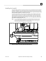
1
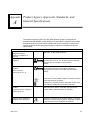
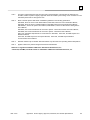
GE Fanuc Automation
Programmable Control Products
Installation Requirements
for Conformance to Standards
GFK-1179J
March 2005
GFL-002
Warnings, Cautions, and Notes
as Used in this Publication
Warning
Warning notices are used in this publication to emphasize that hazardous
voltages, currents, temperatures, or other conditions that could cause personal
injury exist in this equipment or may be associated with its use.
In situations where inattention could cause either personal injury or damage to
equipment, a Warning notice is used.
Caution
Caution notices are used where equipment might be damaged if care is not
taken.
Note:
Notes merely call attention to information that is especially significant to
understanding and operating the equipment.
This document is based on information available at the time of its publication. While
efforts have been made to be accurate, the information contained herein does not
purport to cover all details or variations in hardware or software, nor to provide for
every possible contingency in connection with installation, operation, or maintenance.
Features may be described herein which are not present in all hardware and software
systems. GE Fanuc Automation assumes no obligation of notice to holders of this
document with respect to changes subsequently made.
GE Fanuc Automation makes no representation or warranty, expressed, implied, or
statutory with respect to, and assumes no responsibility for the accuracy,
completeness, sufficiency, or usefulness of the information contained herein. No
warranties of merchantability or fitness for purpose shall apply.
The following are trademarks of GE Fanuc Automation North America, Inc.
Alarm Master
CIMPLICITY
CIMSTAR
Field Control
FrameworX
GEnet
Genius
Helpmate
Logicmaster
Modelmaster
Motion Mate
PACSystems
Proficy
ProLoop
PROMACRO
PowerMotion
PowerTRAC
Series 90
Series Five
Series One
Series Six
Series Three
VersaMax
VersaPoint
VersaPro
VuMaster
Workmaster
©Copyright 1995—2005 GE Fanuc Automation North America, Inc.
All Rights Reserved.
Preface
This manual describes the installation requirements for programmable control products
used in industrial environments, specifically, in situations where compliance to standards
or directives from the Federal Communications Commission, the Canadian Department of
Communications, or the European Union is necessary. The information in this manual is
applicable for GE Fanuc Series 90-70 and Series 90-30 programmable controller
products, Genius I/O products, VersaMax I/O, and Field Control Distributed I/O and
Control products.
Revisions to this Manual
The following is a list of the revisions to this manual as compared to version GFK-1179J:
Removed obsolete list of translated materials (chapter 1). For current product
documentation, please refer to http://www.gefanuc.com/.
Updated product agency approvals, standards, and general specifications information
(appendix A).
New radiated emissions-compliant products (appendix D).
Related Publications
For more information, refer to these publications:
Genius® I/O System User’s Manual, GEK-90486-1
Genius® I/O Discrete and Analog Blocks User’s Manual, GEK-90486-2
Series 90™-70 PLC Installation Manual, GFK-0262
Series 90™-70 PLC Data Sheets Manual, GFK-0600
Series 90™-30 PLC Installation Manual, GFK-0356
Series 90™-30 I/O Specifications Manual, GFK-0898
Field Control™ Distributed I/O and Control System, Genius® Bus Interface Unit User’s
Manual, GFK-0825
Field Control™ Distributed I/O and Control System, I/O Modules User’s Manual,
GFK-0826
VersaMax™ I/O and Option Modules Manual, GFK-1504
VersaMax™ Network Interface Units Manual, GFK-1535
These publications and additional product documentation are available at
http://www.gefanuc.com/
GFK-1179J
iii
Contents
Installation Guidelines .................................................................................................. 1-1
Introduction ..................................................................................................................... 1-1
Government Regulations ............................................................................................... 1-2
Verification and Industrial Exemption for U.S. and Canadian Installations....................... 1-2
New Approach Directives............................................................................................... 1-3
EMC Directive .................................................................................................................. 1-4
Grounding the Controls Enclosure .................................................................................... 1-5
Cable Shield Clamping Assembly..................................................................................... 1-6
I/O Power Sources ............................................................................................................ 1-6
All Analog Modules ........................................................................................................... 1-6
Series 90-30 Products....................................................................................................... 1-7
General Installation Guidelines................................................................................... 1-7
Safety and Reference Ground.................................................................................... 1-8
Additional Guidelines for Specific Components ......................................................... 1-8
Series 90-70 Products..................................................................................................... 1-11
General Installation Guidelines................................................................................. 1-11
Safety and Reference Ground.................................................................................. 1-11
Additional Guidelines for Specific Components ....................................................... 1-12
Genius I/O Products ........................................................................................................ 1-13
General Installation Guidelines................................................................................. 1-13
Additional Guidelines for Specific Components ....................................................... 1-13
Field Control Products..................................................................................................... 1-14
General Installation Guidelines................................................................................. 1-14
Genius Stations ........................................................................................................ 1-14
FIP Stations .............................................................................................................. 1-14
PROFIBUS Station ................................................................................................... 1-15
Additional Guidelines for Specific Components ....................................................... 1-15
VersaMax Products ......................................................................................................... 1-16
General Installation Guidelines................................................................................. 1-16
DataPanel Products ........................................................................................................ 1-16
Low Voltage Directive................................................................................................... 1-17
Installation Requirements................................................................................................ 1-17
Series 90-30 Products .............................................................................................. 1-18
Handling Modules ........................................................................................................... 1-18
Machinery Directive ...................................................................................................... 1-19
ATEX Directive............................................................................................................... 1-21
Installation Requirements................................................................................................ 1-21
GFK-1179J
v
Contents
Safety-Related Guidelines for Installation in the European Union ........................... 2-1
Introduction ..................................................................................................................... 2-1
General ............................................................................................................................. 2-1
Qualified Personnel ........................................................................................................ 2-1
Proper Usage ................................................................................................................... 2-2
Guidelines for the Application Planning and Installation of the Product.................. 2-2
Product Agency Approvals, Standards, and General Specifications .......................A-1
Cable Shield Clamping Assembly................................................................................B-1
Features ...........................................................................................................................B-1
Functions .........................................................................................................................B-2
Installing the Assembly ..................................................................................................B-3
Maximum and Minimum Diameter Cable ..........................................................................B-4
Removing Cable Cover .....................................................................................................B-4
Mounting on a Series 90-70 PLC Rack.............................................................................B-5
Shielded Cable Alternative to Conduit ........................................................................C-1
Communication Cables ..................................................................................................C-1
I/O Cables.........................................................................................................................C-1
Analog/High Speed Cables ............................................................................................C-1
Power Input to Enclosure...............................................................................................C-2
AC Power Input RF Filter............................................................................................C-2
DC Power Input RF Filter ...........................................................................................C-2
Shield Termination ..........................................................................................................C-3
Compression Connectors ...........................................................................................C-3
Specialty Shielded Cable Vendors ................................................................................C-4
Radiated Emissions Compliant Products ...................................................................D-1
Industrial Exemption Products ....................................................................................E-1
vi
Installation Requirements for Conformance to Standards –March 2005
GFK-1179J
Contents
Figure 1-1. GE Fanuc’s Path to Comply with the EMC Directive .................................................................. 1-3
Figure 1-2. Recommended System Grounding ............................................................................................. 1-5
Figure 1-3. Alternative to Cable Shield Clamping Assembly........................................................................ 1-6
Figure 1-4. Installed PLC System .................................................................................................................. 1-7
Figure 1-5. Communication Cable Requirements ...................................................................................... 1-15
Figure 1-6. GE Fanuc’s path to comply with the Low Voltage Directive...................................................... 1-17
Figure 1-7. GE Fanuc’s path for supporting machine manufacturer’s compliance with the
Machinery Directive ........................................................................................................... 1-18
Figure 1-8. GE Fanuc’s path to comply with the ATEX Directive ................................................................ 1-20
Figure B-1. Ground Plate Outline, Mounting Dimensions, and Cable Clamp................................................B-2
Figure B-2. Example of Cable Shield Clamping Assembly Installation .........................................................B-3
Figure B-3. Cross Section of Cable Secured by Clamp ................................................................................B-4
Figure B-4. Clamped Cable with Exposed Shield..........................................................................................B-4
Figure B-5. Cable Shield Clamping Assembly Mounted on a Series 90-70 PLC Rack.................................B-5
Figure C-1. Unshielded I/O Cable with a Single Shield .................................................................................C-3
Figure C-2. Communication Cables Sharing an RF Shield ...........................................................................C-3
GFK-1179J
Contents
vii
Chapter
Installation Guidelines
1
Introduction
The installation manuals for each product line provide detailed information regarding the
equipment’s proper installation, startup, and use. This manual provides the additional
installation requirements needed to comply with governing bodies and standards
agencies, such as Federal Communications Commission (FCC), Industry Canada and
Standards Council of Canada (SCC), European Union (EU), and Australian
Communications Authority (ACA).
This manual describes the standards to which GE Fanuc products must conform for
installation in industrial environments. The information in this manual is applicable for the
following GE Fanuc product lines: Series 90-70, Series 90-30, Field Control, Genius,
VersaMax, QuickPanel, DataPanel, and Operator Interface.
This chapter discusses the following regulations and directives:
Government Regulations
New Approach Directives
EMC Directive
Low Voltage Directive
Machinery Directive
ATEX Directive
GFK-1179J
1-1
1
Government Regulations
U.S., Canadian, and Australian regulations are intended to prevent equipment from
interfering with approved transmissions or with the operation of other equipment through
the AC power source.
The Series 90-70, Series 90-30, Field Control, Genius, and VersaMax products have been
tested and found to meet or exceed the requirements of U.S. (47 CFR 15), Canadian
(ICES-003), Australian (AS/NZS 3548), and European (EN55022) regulations for Class A
digital devices when installed in accordance with the guidelines noted in the appropriate
product section. These various regulations share commonality in content and test levels
with that of CISPR 22 and based on this commonality testing to the each individual
standard was deemed unnecessary.
The FCC requires the following note to be published according to FCC guidelines:
Note:
This equipment has been tested and found to comply with the limits for a Class A
digital device, pursuant to Part 15 of the FCC Rules. These limits are designed to
provide reasonable protection against harmful interference when the equipment is
operated in a commercial environment. This equipment generates, uses, and can
radiate radio frequency energy and, if not installed and used in accordance with
the instruction manual, may cause harmful interference to radio communications.
Operation of this equipment in a residential area is likely to cause harmful
interference in which case the user will be required to correct the interference at
his own expense.
Industry Canada requires the following note to be published:
Note:
This Class A digital apparatus complies with Canadian ICES-003.
Verification and Industrial Exemption for U.S. and Canadian Installations
With regard to U.S. and Canadian installation regulations, users may wish to consider the
industrial plant provisions of FCC regulation 47 CFR 15.103(b) and Industry Canada
regulation ICES-003, Section 1.2.2(b). Appendix E contains a list of all GE Fanuc products
that have taken this Industrial Exemption. For products not mentioned in Appendix E, GE
Fanuc has elected the "verification" route to Canadian and U.S. compliance.
1-2
Installation Requirements for Conformance to Standards – March 2005
GFK-1179J
1
New Approach Directives
Historically, the Member States of the European Union (EU) had separate laws and
regulations relating to safety and other technical issues. These laws effectively
represented technical barriers to trade between the member states (and between them
individually and external nations). With the interest of promoting the free movement of
goods across national borders, the European Community agreed on a New Approach to
technical harmonization. These New Approach Directives provide only “essential
requirements” which can be met either through the use of Harmonized Standards or by
other defined means. Compliance with standards is not a mandatory requirement of these
directives. The directives are given the force of law in Member States through enactment
of national legislation harmonized through reference to a common source document. The
European free trade area has been extended under the European Economic Area
Agreement 1993 to include the 15 countries within the EU plus 3 EFTA members but not
Switzerland. The EEA now comprises of 28 members as 10 new countries were recently
added. The "CE Marking" must be affixed to products meeting the requirements of all
applicable EU directives that are in force, and that require it. Products bearing “CE
Marking” are presumed to comply with the directive(s).
EU directives that might apply directly to GE Fanuc’s PLC products:
The EMC Directive (89/336/EEC, 92/31/EEC, 93/68/EEC) deals with electromagnetic
emissions and immunity.
The Low Voltage Directive (73/23/EEC, 93/68/EEC) deals with electrical safety.
The ATEX Directive (94/9 EC) deals with equipment and protective systems intended
for use in potentially explosive atmospheres.
GE Fanuc PLC products meet the CE-Marking Directive (93/68/EEC) indicating
compliance to both EMC Directive, Low Voltage Directive, and ATEX Directive (if
required). In addition, GE Fanuc will issue Declarations of Conformity that specify the
directive(s) and the catalog numbers of the products covered. PLC products must be
installed using the instructions in the installation manuals and in the applicable sections of
this manual.
Manufacturers of machines to be installed within the EEA must also comply with the
following directive:
The Machinery Directive (89/392/EEC, 91/368/EEC, 93/44/EEC, 93/68/EEC) deals
with machine safety.
The Machinery Directive applies to the entire machine and covers all safety aspects of the
machine, including electrical safety. Compliance with the Machinery Directive is the
machine manufacturer’s responsibility. GE Fanuc supports machine manufacturers by
complying with the safety requirements of IEC 1131-2, the applicable European standard
for programmable controllers.
GFK-1179J
Chapter 1 Installation Guidelines
1-3
1
EMC Directive
The EMC Directive is concerned with the immunity of electrical equipment to a variety of
interference sources and the emissions from electrical equipment that could interfere with
the operation of other equipment. The EMC Directive applies to complete installations,
and since GE Fanuc PLCs are included in the installation, GE Fanuc is supporting the
EMC Directive by testing and CE marking a subset of our equipment.
EMC Directive
89/336/EEC
92/31/EEC
GE Fanuc PLC Products Will Comply
93/68/EEC
Article 10(2) Competent Body Route to Compliance
Technical Construction File
GE Fanuc Declaration of Conformity
Figure 1-1. GE Fanuc’s Path to Comply with the EMC Directive
The European Union allows manufacturers to self-certify that their products comply with
the EMC Directive. Alternately, manufacturers may base their compliance on a Technical
Construction File (TCF), which is assessed by an EU-authorized Competent Body. GE
Fanuc has elected the TCF approach. Compliance specifications are summarized by the
EMC Emissions, EMC Immunity, and Power Supply sections found in Appendix A.
GE Fanuc has issued Declaration of Conformity (DoC) documents for each family of
products, thereby indicating compliance with the CE Marking Directive (93/68/EEC). The
DoC documents contain a list of all products, which are labeled with the CE mark. These
DoC documents can be accessed through GE Fanuc Automation's World Wide Web site.
The following section specifies additional installation and application practices necessary
to meet the EMC Directive for wiring that leaves the control cabinet and travels through a
factory environment. Wiring leaving the cabinet may be exposed to interference sources
corresponding to the standards and levels specified in Appendix A. The installation
practices found in the individual product installation manuals must also be followed.
1-4
Installation Requirements for Conformance to Standards – March 2005
GFK-1179J
1
Grounding the Controls Enclosure
Locally applicable grounding safety regulations and machinery directives should be
followed for providing a protective ground to earth. In addition, the following safety
guidelines should be followed:
Ground conductors should be as short and as large in size as possible. The
conductors must always be large enough to carry the maximum short circuit current of
the path being considered. Braided straps or ground cables (typically green insulation
with a yellow tracer — AWG #12 [3.3 mm2] or larger) can be used to minimize
resistance.
The PLC equipment, other control equipment, and the machine should be
interconnected to maintain a common earth ground reference, also called the machine
chassis ground.
Ground conductors should be connected in a tree fashion with branches routed to a
central earth ground point. This ensures that no ground conductor carries current from
any other branch. This method is shown in Figure 1-2.
PLC Cabinet
Rack
Programming
Device
Motor Drives
and other
Electrical
Control
Equipment
Machinery
Rack
NOTE
Earth
Ground
Central
Ground Point
Signal and power
connections
are not shown.
Figure 1-2. Recommended System Grounding
The EMC ground deals with the ability of the system to conduct interference energy
transformed into a high frequency and high amplitude current to the machine chassis
without causing secondary interference. The EMC ground requires the following:
GFK-1179J
The EMC ground must be a low impedance, low inductance path to the machine
chassis ground.
The baseplate on which the PLC is mounted should be connected to the machine
chassis ground by a wire with a 10:1 length-to-width ratio to provide a high frequency
path. (A worst-case installation simulated for EMC testing used a 2-meter, 12 AWG
wire.)
Chapter 1 Installation Guidelines
1-5
1
Cable Shield Clamping Assembly
A cable shield clamping assembly (IC697ACC736) is available to provide higher EMC
immunity for shielded cables in severe industrial environments. This assembly provides a
high frequency ground for shielded cables via a ground plate and six cable clamps. (A set
of 12 additional cable clamps can be ordered–IC697ACC737.) Refer to Appendix B for
detailed installation and usage information about the assembly. As an alternative, high
frequency grounds for shields can be fabricated from suitable material. An example is
shown below with the insulating cover of the cable stripped back.
a45528
User-provided clamp
Strip wire
to expose
shield.
Figure 1-3. Alternative to Cable Shield Clamping Assembly
I/O Power Sources
All power sources needed by the PLC equipment for I/O (discrete and analog) must be
appropriately conditioned to not exceed both the I/O EMC levels specified in Appendix A
for EN61000-4-4 and the 1 kilovolt common mode and differential mode with 42Ω source
impedance for EN 61000-4-5.
All Analog Modules
All analog modules, including RTD and Thermocouple modules, must have shielded cable
connections with the shield grounded at one end (at source).
1-6
Installation Requirements for Conformance to Standards – March 2005
GFK-1179J
1
Series 90-30 Products
General Installation Guidelines
In order to meet U.S., Canadian, Australian, and European regulations for Class A digital
devices, all applicable products in the Series 90-30 PLC product line have complied with
EN55022 standard when installed as follows:
An external ground wire (16 AWG [1.32mm2] of shortest possible length approx. 6 - 7"
[15.24- 17.78cm]) must be wired from the Series 90-30 power supply safety ground
wire terminal to the metal base plate. See Figure 1-4.
In order to meet U.S., Canadian, Australian, and European regulations for Class A digital
devices, all applicable products in the Series 90-30 PLC product line, except those listed
in Appendix D, have complied with EN55022 standard when installed as follows:
The PLC system must be mounted in a metal enclosure or the equivalent. All surfaces
of the enclosure must be adequately grounded to adjacent surfaces to provide
electrical conductivity. Wiring external to the enclosure must be routed in metal
conduit or the equivalent. Using shielded cables and power line filtering, as detailed in
Appendix C, is equivalent to using metal conduit.
The conduit must be mounted to the enclosure using standard procedures and
hardware to ensure electrical conductivity between the enclosure and conduit. The
termination for the shielded cable alternative to conduit is detailed in Appendix C.
Power Supply
Inputs
H
N
G
Power Supply
Safety Ground
Series 90-30 PLC
System
Metal Baseplate
EMC Ground
Figure 1-4. Installed PLC System
GFK-1179J
Chapter 1 Installation Guidelines
1-7
1
Safety and Reference Ground
The metal back of the baseplate is ground, when properly installed. Safety and reference
ground connections should be made from one of the mounting tabs to earth ground using
a minimum AWG #12 (3.3 mm2) wire and a ring terminal. The use of a nut and star
washer for each wire on the ground connection lug is recommended to ensure adequate
grounding.
Warning
The baseplate must be grounded to minimize electrical shock hazard, which
may result in severe personal injury.
All baseplates grouped together in a Series 90-30 PLC system must have a common ground
connection. This is especially important for baseplates that are not mounted in the same
control cabinet.
The best way to provide proper ground connections is to ensure that the Series 90-30 PLC
baseplate metal frame is directly connected to the control panel in which the baseplate or
baseplates are mounted. This can be accomplished by connecting a ground strap from one
of the ground lugs on either side of the baseplate to the control panel or cabinet following
applicable electrical safety codes.
Additional Guidelines for Specific Components
The guidelines specified in this section must be followed in addition to the guidelines
found in the general installation guidelines for the product line.
Expansion and Remote Cables
Custom length expansion and remote cables must be 100% shielded to meet the
immunity levels specified in Appendix A. A 100%, or continuous, shield means that the
braided cable shield is connected to the metal shell of the connector around the entire
perimeter of the connector. This shielding provides a low impedance path to earth ground
for any noise energy that is coupled onto the cable shield. Refer to the Series 90-30
Installation Manual, GFK-0356L or later, for details on cable construction.
IC693ALG392/442
In order to meet the EN 61000-4-3 levels specified in Appendix A when an IC693ALG392
or IC693ALG442 module is installed in a control system, the Series 90-30 PLC system
must be mounted in a metal enclosure.
IC693APU300
Shielded cable must be used for cables connecting to the IC693APU300 High Speed
Counter. The shield for the cable must have a high frequency ground within 6 inches
(15.24 cm) of the IC693APU300 module in order to meet the EN 61000-4-4 levels
specified in Appendix A. The cable’s length is limited to 30 meters.
1-8
Installation Requirements for Conformance to Standards – March 2005
GFK-1179J
1
IC693APU301/302
The Axis Positioning Modules have two faceplate connectors, marked A and B, for User
I/O. In order for Axis Positioning Modules IC693APU301 (version I or earlier) and
IC693APU302 (version K or earlier) to meet the EN 61000-4-4 levels specified in
Appendix A, the shield wire must be connected directly to ground. To make this
connection, disconnect the User I/O connector cable (IC693CBL311) drain wire from pin
B12 (frame ground) of each I/O connector and directly connect it to ground with a 16 AWG
(1.32 mm2) wire 8 inches (20.32 cm) maximum in length. Optional cables IC693CBL317
(3 m) and IC693CBL320 (1 m) are already modified to the above dimensions. The cable
connected to the SNP port for downloading user programs must be less than 30 meters.
Please refer to Appendix C of the APM User’s Manual for the I/O connector cable
specifications.
Axis Positioning Modules IC693APU301 (version J or later) and IC693APU302 (version H
or later) do not require the cable connector to be disconnected. The standard user I/O
cable (IC693CBL311 [3 m] or IC693CBL319 [1 m]) satisfies the EN 61000-4-4
requirements. However, for best results, a high frequency ground (FANUC clamp) for the
cable shield should be used. Optional cables IC693CBL317 (3 m) and IC693CBL320 (1
m) provide better noise suppression than the standard I/O cables without the high
frequency ground.
IC693CMM321
When the RS485 port of the Ethernet module is used, in order to meet the EN 61000-4-4
levels specified in Appendix A, a high frequency ground for the RS485 cable shield is
required within 12 inches of the module. The shield conductor should remain continuous
to the module, and insulation should be removed only at the grounding point. For more
information, please refer to “Cable Shield Clamping Assembly” earlier in this chapter.
IC693CPU351
In order to meet the EN 61000-4-4 levels specified in Appendix A, the ground wire and
grounding bracket of the IC693CPU351 must be installed as outlined in the Series 90-30
Installation Manual (GFK-0356L or later). Optionally, the ground wire and a high frequency
ground for the cable shield within 12 inches of the module may be used. The shield
conductor should remain continuous to the module, and insulation should be removed
only at the grounding point. For more information, please refer to “Cable Shield Clamping
Assembly” on page earlier in this chapter.
IC693MCM001
In order to meet the EN 61000-4-2 levels specified in Appendix A, when an
IC693MCM001 module is installed in a control system, the Series 90-30 PLC system must
be mounted in a metal enclosure. In order to meet EN55022 Group 1, Class A Radiated
Emissions levels, the metal enclosure should provide a metal-on-metal connection around
the door. In order to meet the EN 61000-4-4 and EN 61000-4-5 levels specified in
Appendix A, the continuous shielded servo command cables should be clamped at both
ends (at module and at servo) using a high-frequency ground. For more information,
please refer to “Cable Shield Clamping Assembly” earlier in this chapter.
GFK-1179J
Chapter 1 Installation Guidelines
1-9
1
IC693MDL654
Conventional TTL wiring practices should be utilized when installing this module. For
noise immunity reasons, I/O control lines connected to this module must be less than 30
meters in length (however, signal attenuation considerations will constrain practical wiring
length to less than this maximum specification).
IC693PRG300
For installations in which the Hand-Held Programmer is permanently installed, the
shielded cable to the Hand-Held Programmer must have a high frequency ground for the
shield within 13” ( 33 cm) of the Hand-Held Programmer in order to meet the EN 61000-44 levels specified in Appendix A. The shield on the cable must continue to the Hand-Held
Programmer.
IC693PWR322/328
In order to meet EN55022 Group 1, Class A Radiated Emission levels, this module
requires two small turns on the incoming DC power lines to be placed around a ferrite
clamp (Steward Part #A2029-0A0 or ferrite with similar characteristics).
1-10
Installation Requirements for Conformance to Standards – March 2005
GFK-1179J
1
Series 90-70 Products
General Installation Guidelines
In order to meet U.S., Canadian, Australian, and European regulations for Class A digital
devices, all applicable products in the Series 90-70 PLC product line have complied with
EN55022 standard when installed as follows:
The PLC system must be mounted in a metal enclosure with a metal-on-metal
connection around the door or the equivalent. All surfaces of the enclosure must be
adequately grounded to adjacent surfaces to provide electrical conductivity. Wiring
external to the enclosure must be routed in metal conduit or the equivalent. Using
shielded cables and power line filtering, as detailed in Appendix C, is equivalent to
using metal conduit.
The additional safety ground wire provided with the Series 90-70 power supply must
be wired from the Series 90-70 rack ground stud to the power supply safety ground
wire terminal.
The conduit must be mounted to the enclosure using standard procedures and
hardware to ensure electrical conductivity between the enclosure and conduit. The
termination for the shielded cable alternative to conduit is detailed in Appendix C.
Safety and Reference Ground
The metal back of the baseplate is ground, when properly installed. Safety and reference
ground connections should be made from one of the mounting tabs to earth ground using
a minimum AWG #12 (3.3 mm2) wire and a ring terminal. Use of a nut and star washer for
each wire on the ground connection lug is recommended to ensure adequate grounding.
Warning
The baseplate must be grounded to minimize electrical shock hazard, which
may result in severe personal injury.
All baseplates grouped together in a Series 90-70 PLC system must have a common
ground connection. This is especially important for baseplates that are not mounted in the
same control cabinet.
The best way to provide proper ground connections is to ensure that the Series 90-70
PLC baseplate metal frame is directly connected to the control panel in which the
baseplate or baseplates are mounted. This can be accomplished by connecting a ground
strap from one of the ground lugs on either side of the baseplate to the control panel or
cabinet following applicable electrical safety codes.
GFK-1179J
Chapter 1 Installation Guidelines
1-11
1
Additional Guidelines for Specific Components
The guidelines specified in this section must be followed in addition to the guidelines
found in the general installation guidelines for the product line.
IC697BEM741/742 and IC687BEM741/742
In order to meet EN 61000-4-2 (8 kV Air), the communication ports (channels 1 and 2) of
the FIP Bus Controller should be connected to the FIP network with an ITT Cannon FBC
115 434-2 or FBC 115 434-3 cable (or cable with a similar plastic connector shell);
otherwise, the provided plastic connector cover and nylon screws should be used to cover
the exposed metal connector of the FIP communication port.
IC697MCM001
In order to meet EN55022 Group 1, Class A Radiated Emissions levels, as an alternative
to conduit, each shielded servo cable should have a ferrite located approximately 1–2
inches (2.54–5.08 cm) away from the port and a high frequency ground at the entrance to
the enclosure. Also, as stated in Power Mate I Connection Manual (GFZ-62733), the
continuous shielded servo cables should be clamped for proper grounding for compliance
with immunity tests.
IC697MDL651
Conventional TTL wiring practices should be utilized when installing this module. For
noise immunity reasons, I/O control lines connected to this module must be less than 30
meters in length (however, signal attenuation considerations will constrain practical wiring
length to less than this maximum specification).
IC697PCM711/PCM712/CMM711/CMM712/ADC701
Continuous shielded cable must be used for cables connected to the ports on these
modules in order to meet the EN 61000-4-4 levels listed in Appendix A. The continuous
shielded cable must have a high frequency ground within 18 inches (45.72 cm) of the
module to pass the EN 61000-4-6 levels listed in Appendix A. Continuous or 100%
shielded means that the braided cable shield is connected to the metal shell of the
connector around the entire perimeter of the connector. This shielding provides a low
impedance path to frame ground for any noise energy that is coupled onto the cable
shield.
1-12
Installation Requirements for Conformance to Standards – March 2005
GFK-1179J
1
Genius I/O Products
General Installation Guidelines
In order to meet U.S., Canadian, Australian, and European regulations for Class A digital
devices, all applicable products in the Genius product line have complied with EN55022
standard when installed as follows:
The system must be mounted in a metal enclosure or the equivalent. All surfaces of
the enclosure must be adequately grounded to adjacent surfaces to provide electrical
conductivity. Wiring external to the enclosure must be routed in metal conduit or the
equivalent. Using shielded cables and power line filtering, as detailed in Appendix C,
is equivalent to using metal conduit.
The conduit must be mounted to the enclosure using standard procedures and
hardware to ensure electrical conductivity between the enclosure and conduit. The
termination for the shielded cable alternative to conduit is detailed in Appendix C.
In order to meet EN 61000-4-2 and EN 61000-4-3 levels as specified in Appendix A,
all components in a Genius I/O system must be mounted inside a metal enclosure.
Additional Guidelines for Specific Components
The guidelines specified in this section must be followed in addition to the guidelines
found in the general installation guidelines for the product line.
IC660BBA023/103
In the presence of severe RF interference (EN 61000-4-3), the thermocouple lines must
be shielded to minimize any inaccuracies that the interference may cause and to meet
compliance.
IC660ELB921/ELB922
When the length of the Genius communication cable from the PC Interface Module
(PCIM) to the first Genius drop exceeds 30 meters, an external clamp on ferrites must be
used. Fair-Rite Products Corporation ferrites, as shown in the following table, or
equivalent parts may be used.
Fair-Rite
Part No.
Max. Cable
Diameter
Impedance (Ω )
25 MHz Minimum
Impedance (Ω )
25 MHz Minimum
Description
2643164251
.250”
130
275
core only
2643167251
2643164151
.390”
.500”
110
125
225
250
core only
core only
0199164251
0199167251
.250”
.390”
—
—
—
—
0199164151
0443194251
.500”
.250”
—
130
—
275
case
case and two ferrite parts
0443167251
0443164151
.390”
.500”
110
125
225
250
case and two ferrite parts
case and two ferrite parts
GFK-1179J
Chapter 1 Installation Guidelines
case
case
1-13
1
Field Control Products
General Installation Guidelines
In order to meet U.S., Canadian, Australian, and European regulations for Class A digital
devices, all applicable products in the Field Control product line have complied with
EN55022 standard when installed as follows:
The Field Control product must be mounted on a conductive surface DIN rail. Refer to
the Field Control Distributed I/O and Control System Genius Bus Interface Unit User’s
Manual, GFK-0825, for dimensions.
The DIN rail must be mounted on a metallic surface (panel) that is grounded to earth.
The DIN rail must be grounded to the metallic surface (panel) every 6 inches (15.24
cm) with screws and star washers.
The safety ground wire (14 AWG [2.10 mm2]) for the Bus Interface Unit and the I/O
bases must be a maximum of 4 inches (10.16 cm) in length to the panel.
The panel ground wire (14 AWG [2.10 mm2]) for the auxiliary terminal strip for analog
shields must be a maximum of 4 inches (10.16 cm) in length to the panel.
Genius Stations
The Genius Station (IC670GBI002 and IC670GBI102) has no specific installation
guidelines to meet EN55022 Group 1, Class A Radiated Emission levels. The
communication cable from one Bus Interface Unit to another may be any cable approved
for use with the communication network. However, the communication cable from the
controlling equipment to the Bus Interface Unit must be conditioned per the requirements
of the controlling equipment. An example is shown in Figure 1-5 for a Genius Bus
Interface Unit.
FIP Stations
IC670FBI002
The IC670FBI002 FIP BIU has no specific installation guidelines to meet EN55022 Group
1, Class A Radiated Emission levels. The communication cable from one Bus Interface
Unit to another may be any cable approved for use with the communication network.
However, the communication cable from the controlling equipment to the Bus Interface
Unit must be conditioned per the requirements of the controlling equipment. An example is
shown in Figure 1-5 for a Genius Bus Interface Unit.
IC670FBI102
In order to meet the requirements for CE mark approval, all components using the
IC670FBI102 FIP Bus Interface Unit require the following:
1-14
All components must be mounted in a metal enclosure or the equivalent. All surfaces
of the enclosure must be adequately grounded to adjacent surfaces to provide
electrical conductivity.
EMC filter must be installed on the power supply lines.
Ferrite core must be clamped around all discrete I/O lines in FIP Station.
Installation Requirements for Conformance to Standards – March 2005
GFK-1179J
1
In order to pass EN 61000-4-2, HF protection cover (metal cover) must be installed on
the unused D-sub connector.
PLC
PLC
Standard Genius Cable
Conduit, Double-Shield,
or CMS Cable
BIU
BIU
BIU
Figure 1-5. Communication Cable Requirements
PROFIBUS Station
In order to meet EN55022 Group 1, Class A Radiated Emission levels, all components
using the PROFIBUS Station (IC670PBI001) require the following:
All components must be mounted in a metal enclosure or the equivalent. All surfaces
of the enclosure must be adequately grounded to adjacent surfaces to provide
electrical conductivity. Wiring external to the enclosure must be routed in metal
conduit or the equivalent. Using shielded cables and power line filtering, as detailed in
Appendix C, is equivalent to using metal conduit.
The conduit must be mounted to the enclosure using standard procedures and
hardware to ensure electrical conductivity between the enclosure and the conduit. The
termination for the shielded cable alternative to conduit is detailed in Appendix C.
Additional Guidelines for Specific Components
The guidelines specified in this section must be followed in addition to the guidelines
found in the general installation guidelines for the product line.
IC670ALG320
The user supply input must be provided from a power supply in the cabinet, conditioned
by a 30 volt varistor, or wired with a twisted pair shielded cable grounded at the source in
order to not exceed 1 kilovolt common mode and differential mode with 42Ω source
impedance for EN 61000-4-5.
GFK-1179J
Chapter 1 Installation Guidelines
1-15
1
VersaMax Products
General Installation Guidelines
In order to meet U.S., Canadian, Australian, and European regulations for Class A digital
devices, all applicable products in the VersaMax product line have complied with
EN55022 standard when installed as follows:
•
The VersaMax product must be mounted on a conductive surface DIN rail. Refer to
the VersaMax User’s Manuals, GFK-1503, GFK-1504, GFK-1535.
•
The DIN rail must be mounted on a metallic surface (panel) that is grounded to earth.
•
The DIN rail must be grounded to the metallic surface (panel) every 6 inches (15.24
cm) with screws and star washers.
•
The safety ground wire (14 AWG [2.10 mm2]) for the power supply module must be a
maximum of 4 inches (10.16 cm) in length to the panel. Refer to GFK-1515 or GFK1516.
IC200MDD841
To meet the EN 61000-4-4 levels specified in Appendix A, shielded cable properly
terminated to earth ground must be used to connect the count inputs of the
IC200MDD841 High Speed Counter module.
IC200PWR001/002
In order to meet EN61000-4-5 levels specified in Appendix A, external 32V MOV (metal
oxide varistor) suppression is required from both the positive and negative input to frame
ground or at the power line input of a system enclosure. A Harris V36ZA80 MOV, rated
160 joules should be sufficient.
IC200PWR101/102
In order to meet EN61000-4-5 levels specified in Appendix A, external 32V MOV
suppression is required from both the positive and negative input to frame ground or at the
power line input of a system enclosure. A Harris V36ZA80 MOV, rated 160 joules should
be sufficient.
DataPanel Products
IC752DFT100/101
If communications cable or DC power lines exceed 10 meters in length, then an earthground connection should be made to pin 3 of the DC power input terminal.
1-16
Installation Requirements for Conformance to Standards – March 2005
GFK-1179J
1
Low Voltage Directive
The Low Voltage Directive applies to products operating between 50 and 1000 VAC or 75
and 1500 VDC. The emphasis of the Low Voltage Directive is on safety.
Low Voltage
Directive
73/23/EEC
93/68/EEC
GE Fanuc PLC Products Will Comply
IEC 1131-2 Programmable Controllers (Safety Requirements)
Technical File
GE Fanuc Declarations of Conformity
Figure 1-6. GE Fanuc’s path to comply with the Low Voltage Directive
The following sections specify installation and application practices necessary to meet the
Low Voltage Directive.
Installation Requirements
For compliance to the Low Voltage Directive, Series 90-30, Series 90-70, Field Control,
VersaMax and Genius systems and their components are considered open equipment
[i.e. live electrical parts may be accessible to users] and must be installed in an enclosure.
In addition, refer to the installation manual for your system and follow the guidelines for
mounting, spacing, and, if applicable, shielding the devices in your system.
Locally applicable grounding safety regulations and machinery directives should be
followed for providing a protective ground to earth. Refer to “Grounding the Controls
Enclosure” as well as the general installation guidelines for Series 90-30, Series 90-70,
Genius I/O, VersaMax, and Field Control products found in the EMC Directive section of
this manual for additional safety guidelines related to earth grounding.
Note:
Care should be taken regarding installation wiring to ensure proper connections
and to protect against equipment damage or misoperation.
In addition to observing the system grounding procedures recommended for your system,
periodic inspections of the ground connections should be performed to ensure that the
system remains properly grounded.
GFK-1179J
Chapter 1 Installation Guidelines
1-17
1
Series 90-30 Products
To avoid possible misrouting of wiring to I/O modules, the following is recommended:
Label all wires to and from I/O devices. Record circuit identification numbers or other
pertinent data on the inserts that go in the module’s faceplate door.
Wires should be dressed so that each field I/O connector is fixed relative to its
respective module.
Handling Modules
Use the procedures found in the installation manual of your system for the safe and
proper removal of PLC modules.
Warning
Exercise care when working around operating PLC equipment
may become very hot and could cause injury.
1-18
devices
Installation Requirements for Conformance to Standards – March 2005
GFK-1179J
1
Machinery Directive
The Machinery Directive focuses on the safe operation of the entire machine and is the
machine manufacturer’s responsibility.
Machinery
Directive
89/392/EEC
91/368/EEC
93/44/EEC
93/68/EEC
Machine Manufacturer's Responsibility to Comply
EN292-1, -2 Safety of Machinery
EN60204-1 Electrical Equipment of Industrial Machine
IEC 1131-2 Programmable Controllers (Safety Requirements)
GE Fanuc Complies
Figure 1-7. GE Fanuc’s path for supporting machine manufacturer’s compliance with the
Machinery Directive
When applied in accordance with EN60204-1 (Electrical Equipment of Industrial
Machines) and GE Fanuc installation instructions, GE Fanuc PLC products allow a
machine manufacturer to comply with the electrical safety requirements of the Machinery
Directive. Other requirements of the Machinery Directive involving items such as displays,
languages, instructions, Emergency Stop functions, machine operation, protective guards,
and interlocks are the responsibility of the machine manufacturer.
GFK-1179J
Chapter 1 Installation Guidelines
1-19
1
The specific requirements of EN60204-1, IEC 1131-2, and GE Fanuc installation
instructions are as follows:
Compliance with EN292-1 and EN292-2 (Safety of Machinery) as well as EN602041/IEC60204-1 (Electrical Equipment of Industrial Machines) must be observed during
the design phase.
The PLC products must be packaged within an IP54 or higher degree of protection
enclosure.
Negative logic input and output modules cannot be used. (Exception: With safety
agency approval, these devices may be used in safety system “H” configurations.)
The PLC power supply must be supplied through an IEC-rated isolation transformer.
Power supply to the PLC must be controlled to ensure that it does not exceed
overvoltage category II per EN60204-1 (IEC60240-1).
Cable shielding and grounding are the responsibility of the machine builder. GE
Fanuc’s installation instructions and guidelines must be followed.
Installation, operation, and maintenance instructions in the language of the user
country are the responsibility of the machine builder.
Appendix A includes a summary of existing agency approvals issued for GE Fanuc PLC
products. In addition to this summary, selected Series 90-70 and Genius modules have
been approved by TÜV for compliance with DIN VDE 0116 and class 5 of DIN VDE 0801
for use in redundant safety system applications. These safety agency approvals
demonstrate that GE Fanuc PLC products meet essential safety requirements.
1-20
Installation Requirements for Conformance to Standards – March 2005
GFK-1179J
1
ATEX Directive
The ATEX Directive focuses on the safe operation of equipment and protective systems
intended for use in potentially explosive environments.
ATEX
Directive
94/9/EC
GE Fanuc PLC Products Comply
Group 2, Category 3 (II 3 G)
EN50014: 1997 Electrical Apparatus for Potentially Explosive Atmospheres
– General Requirements
EN50021:1999 Electrical Apparatus for Potentially Explosive Atmospheres
– Type of Protection “n”
Technical File
GE Fanuc ATEX Declaration of Conformity
Figure 1-8. GE Fanuc’s path to comply with the ATEX Directive
For Group 2, Category 3 type equipment, compliance to the ATEX Directive is achieved
through a manufacturer’s ‘self-certification’. A Technical File is composed to document
that a product has met the “Essential Health and Safety Requirements” (ESHRs) of the
rd
UK 1996 Regulations. In addition, GE Fanuc obtains an independent 3 party
assessment for each product family.
A Declaration of Conformity (DoC) for each family of products is issued with a list of all
product numbers, which are labeled with the ATEX symbol and CE mark. These DoC
documents can be accessed through GE Fanuc Automation's World Wide Web site.
The following section specifies installation requirements that must be adhered to in order
to maintain compliance with the ATEX Directive.
Installation Requirements
For compliance to the ATEX Directive, Series 90-30, Series 90-70, Field Control, Genius,
and Versamax systems must be installed within a protective enclosure meeting the
following criteria:
IP54 or greater, and
Mechanical strength to withstand an impact energy of 3.5 Joules
In addition the following statements are required to appear:
WARNING - EXPLOSION HAZARD – DO NOT DISCONNECT/REMOVE/WIRE
EQUIPMENT UNLESS POWER HAS BEEN SWITCHED OFF OR THE AREA IS KNOWN
TO BE NON-HAZARDOUS
GFK-1179J
Chapter 1 Installation Guidelines
1-21
Chapter
2
Safety-Related Guidelines for Installation in the
European Union
Introduction
This chapter provides a description of safety-related guidelines for the installation of PLC
systems. It is assumed that personnel who install, operate, and maintain automation
systems that include GE Fanuc products are trained and qualified to perform those
functions. This chapter specifically provides safety-related guidelines for products to be
installed in the European Economic Area (EEA).
General
GE Fanuc product manuals provide information required for the intended use of GE Fanuc
products. The product manuals are written for technically qualified personnel such as
engineers, programmers, or maintenance specialists who have been specifically trained
and are experienced in the field of automation control. Such personnel must possess the
knowledge to correctly interpret and apply the safety guidelines provided in GE Fanuc
product manuals. Should you require further information or face special problems that
have not been dealt with in sufficient detail in the product manuals, please contact your
local GE Fanuc sales or service office or GE Fanuc authorized distributor.
Qualified Personnel
Only qualified personnel should be allowed to specify, apply, install, operate, maintain, or
perform any other function related to the products described in the product manuals.
Examples of such qualified persons are defined as follows:
GFK-1179J
System application and design engineers who are familiar with the safety concepts of
automation equipment.
Installation, startup, and service personnel who are trained to install and maintain
such automation equipment.
Operating personnel trained to operate automation equipment and trained on the
specific safety issues and requirements of the particular equipment.
2-1
2
Proper Usage
The equipment/system or the system components may only be used as described in the
product manuals. GE Fanuc PLC products have been developed, manufactured, tested,
and the documentation compiled in keeping with the relevant safety standards. Handling
instructions and safety guidelines described for planning, installation, proper operation
and maintenance must be followed to ensure safe application and use of the products.
Guidelines for the Application Planning and Installation of the Product
GE Fanuc PLC products generally form a part of larger systems or installations. These
guidelines are intended to help integrate GE Fanuc PLC products into systems and
installations without constituting a source of danger. The following precautions must be
followed:
2-2
Compliance with EN292-1 and EN292-2 (Safety of Machinery) as well as EN602041/IEC60204-1 (Electrical Equipment of Industrial Machines) must be observed during
the design phase.
Opening the housing or the protective cover exposes certain parts of this
equipment/system, which could have a dangerously high voltage level.
Only qualified personnel should be allowed access to this equipment/system.
These persons must be knowledgeable of potential sources of danger and
maintenance measures as set out in the product manuals.
Strictly adhere to applicable safety and accident prevention rules and regulations.
A suitable isolating switch or fuses must be provided in the building wiring system.
The equipment must be connected to a protective ground (PE) conductor.
For equipment or systems with a fixed connecting cable but no isolating switch that
disconnects all poles, a power socket with the grounding pin must be installed.
Before switching on the equipment, make sure that the voltage range setting on the
equipment corresponds to the local power system voltage.
In the case of equipment operating on 24 V DC, make sure that proper electrical
isolation is provided between the main supply and the 24 V supply. Use only power
supplies that meet EN60204-1 (IEC60204-1) requirements.
PLC AC power supply must be supplied through an IEC-rated isolation transformer.
Power supply to the PLC must be controlled not to exceed overvoltage category II per
EN60204-1 (IEC60204-1).
Fluctuations or deviations of the new power supply voltage from the rated value must
not exceed the tolerances specified in the technical specifications. Otherwise,
functional failures or dangerous conditions can occur in the electronic
modules/equipment.
Emergency tripping devices in accordance with EN60204-1/IEC60204-1 must be
effective in all operating modes of the automation equipment. Resetting the
emergency off device must not result in any uncontrolled or undefined restart of the
equipment.
Installation Requirements for Conformance to Standards – March 2005
GFK-1179J
2
GFK-1179J
Automation equipment and its operating elements must be installed in such a manner
as to prevent unintentional operation.
Suitable measurements must be taken to make sure that operating sequences
interrupted by a voltage dip or power supply failure resume proper operation when the
power supply is restored. Care must be taken to ensure that dangerous operating
conditions do not occur even momentarily. If necessary, the equipment must be
forced into the “emergency off” state.
Negative Logic Input and Output Modules cannot be used. (Exception: With safety
agency approval (Such as TÜV on GMR Systems), these devices may be used in
safety system “H” configurations).
Cable shielding and grounding are the responsibility of the machine builder. GE
Fanuc’s installation instructions and guidelines must be followed.
Install the power supply and signal cables in such a manner as to prevent inductive
and capacitive interference voltages from affecting the automation functions.
Measures must be taken when interfacing the inputs and outputs of the automation
equipment to prevent an undefined state from being assumed in the case of a wire
break in the signal lines.
Chapter 2 Safety-Related Guidelines for Installation in the European Union
2-3
Appendix Product Agency Approvals, Standards, and
A
General Specifications
The products supplied by GE Fanuc are global products, which are designed and
manufactured with ISO9001 quality assurance for application in industrial environments
throughout the world. They should be installed and used in conformance with product
specific guidelines as well as the following agency approvals, standards and general
specifications:
Agency Approvals Overview 1
Quality Assurance in
Design/Development,
Production, Installation, &
Servicing
ISO9001
Comments
Certification4 by BSI Quality Assurance
N.A. Safety for Industrial Control
Equipment
Certification by Underwriter's Laboratories to UL508 standard and
equivalent CSA C22.2 No 142 - M1987 standard for selected
Series 90, Genius, VersaMax, and Field Control
modules
N.A. Safety for Hazardous
Locations
Class I, Division 2,
Gas Groups A, B, C, D
Certification by Underwriter's Laboratories to UL1604 standard
and equivalent CSA C22.2 No 213-M1987 standard for
selected Series 90, Genius, Versa Max, and Field Control
modules
Certification by Factory Mutual to FM3611 standard for selected
Genius and Series 90-70 modules
Certification by Canadian Standards Association to CSA C22.2
No 213-M1987 standard for selected Genius modules
European Safety for Hazardous
Locations
Equipment Group II, Category 3,
Gas Groups A, B, C
Certification in accordance with European ATEX Directive for
selected Series 90, Genius, Versa Max, and Field Control
modules. Refer to ATEX Declaration of Conformity
European Safety and EMC for
Industrial Control Equipment
Certification in accordance with European EMC & Low Voltage
Directives for selected Series 90, Genius, Versa Max, and Field
Control modules. Refer to Declaration of Conformity
GFK-1179J
A-1
A
Standards Overview2, 4
Conditions
Environmental
Vibration
IEC60068-2-6
1G @57-150Hz, 0.012in p-p @10-57Hz
Shock
IEC60068-2-27
15G, 11ms
Operating
Temperature3
0°C to 60°C: Series 90 [inlet], Genius [ambient], VersaMax [ambient]
0°C to 55°C: Field Control [ambient]
Storage
Temperature
-40°C to +85°C
Humidity
5% to 95%, non-condensing
Enclosure
Protection
IEC60529
Steel cabinet per IP54: protection from dust & splashing water
CISPR 11/EN
55011
“Industrial Scientific & Medical Equipment”
(Group 1, Class A)
CISPR 22/EN
55022
47 CFR 15
“Information Technology Equipment” (Class A)
EMC Emissions
Radiated,
Conducted
EMC Immunity
Electrostatic
Discharge
RF Susceptibility
Fast Transient
Burst
Surge Withstand
Conducted RF
referred to as FCC part 15, “Radio Devices” (Class A)
[applies to CE Marked modules]
EN 61000-4-2*
8KV Air, 4KV Contact
EN 61000-4-3*
10Vrms /m, 80Mhz to 1000Mhz, 80% AM
ENV 50140/
ENV 50204
VersaMax: All power supply, I/O, and communication modules
EN 61000-4-4*
2KV: power supplies, 1KV: I/O, communication
ANSI/IEEE
C37.90a
Damped Oscillatory Wave: 2.5KV:
power supplies, I/O [12V—240V]
IEC255-4
Damped Oscillatory Wave: Class II,
power supplies, I/O [12V—240V]
EN 61000-4-5*
Field Control and VersaMax: 2 kV cm(P/S); 1 kV cm (I/O)
VersaMax: All power supply, I/O, and communication modules
EN 61000-4-6*
10Vrms, 0.15 to 80Mhz, 80%AM: comm. modules w/ cables >30m
VersaMax: All power supply, I/O, and communication modules
Power Supply
Input Dips,
Variations
EN 61000-4-11* During Operation: Dips to 30% and 100%, Variation for AC ±10%, Variation
for DC ±20%
* EN 61000-4-x series of tests are technically equivalent to the IEC 61000-4-xs.
A-2
Installation Requirements for Conformance to Standards – March 2005
GFK-1179J
A
Note 1:
The agency approvals listed in this document and on the Declaration of Conformities are believed to be
accurate, however a product’s agency approvals should be verified by the marking on the unit itself. For more
information please refer to www.gefanuc.com
Note 2:
Refer to module specific data sheets & installation guidelines in the following publications:
GFK-0600, Series 90-70 PLC Data Sheets Manual; GFK-0262, Series 90-70 PLC Installation Manual;
GFK-0356, Series 90-30 PLC Installation Manual; GFK-0898, Series 90-30 I/O Specifications Manual;
GEK-90486-1, Genius I/O System User's Manual; GEK-90486-2, Genius I/O Discrete and Analog Blocks
User's Manual;
GFK-0825, Field Control Distributed I/O and Control System - Genius Bus Interface Unit User's Manual;
GFK-0826, Field Control Distributed I/O and Control System - I/O Module's User's Manual;
GFK-1179, Installation Requirements for Conformance to Standards; GFK-1503, VersaMax System PLC
Reference Manual;
GFK-1504, VersaMax System I/O and Option Modules; GFK-1535, VersaMax System Network
Communications User's Manual.
Note 3:
Selected modules may be derated. Selected modules may also have lower operating ambient temperature.
Note 4:
Applies to GE Fanuc products designed and built in Charlottesville.
®Genius is a registered trademark of GE Fanuc Automation North America, Inc.
™Series 90, VersaMax, and Field Control are trademarks of GE Fanuc Automation Americas, Inc.
GFK-1179J
Appendix A Product Agency Approvals, Standards, and General Specifications
A-3
Appendix Cable Shield Clamping Assembly
B
This Appendix describes the Cable Shield Clamping Assembly for use with Series 90-30
and Series 90-70 Programmable Logic Controllers that are installed in severe industrial
environments and must meet the requirements for higher EMC immunity.
Features
The Cable Shield Clamping Assembly features the following:
GFK-1179H
Provides for higher EMC (Electromagnetic Compatibility) immunity for shielded
cables
Use for installations in severe industrial environments
Use with all Series 90-30 and Series 90-70 PLC products
Easy to assemble
Mounts on panel, rack enclosure, or directly onto a Series 90-70 PLC rack
B-1
B
Functions
The Cable Shield Clamping Assembly, IC697ACC736, contains the parts necessary for
providing higher EMC immunity for shielded cables in PLCs installed in severe industrial
environments.
The Cable Shield Clamping Assembly must be used in severe industrial environments to
provide higher EMC immunity for shielded cables. Shield grounding is accomplished using
the ground plate and cable clamps provided in the kit.
The Cable Shield Clamping Assembly package includes:
One ground plate
Six cable clamps
Four #6 self-tapping screws
Outline Drawing of Mounting Plate
Figure B-1 is an outline drawing of the mounting plate showing dimensions required for
mounting. The figure also shows a cable clamp.
2.95"
19.00"
(75 mm)
(483 mm)
.250"(6.35 mm) dia. (QTY.2)
18.31"
(465 mm)
4.25"
(108 mm)
Mounting
Surface
Side View with
Spacing Requirements
Front View with Mounting Dimensions
Cable Clamp
(Six cable clamps included with assembly.)
* Additional cable clamps available (12 per package), catalog number IC697ACC737.
Figure B-1. Ground Plate Outline, Mounting Dimensions, and Cable Clamp
B-2
Installation Requirements for Conformance to Standards – March 2005
GFK-1179J
B
Installing the Assembly
The ground plate should be mounted near the PLC rack for both Series 90-70 and Series
90-30 PLC installations. The cable clamp provides mechanical relief as well as electrical
grounding. A typical installation is shown in Figure B-2 below. Figure B-5 shows the Cable
Clamp Assembly installed on a Series 90-70 PLC rack.
The cable clamp attaches to the ground plate by sliding it into two adjacent slots at the
selected location for the cable. The cable is inserted between the ground plate and the
cable clamp after removing the required section of the cable’s outer cover. Tighten the
cable clamp by turning the thumbscrew clockwise. Do not over-tighten the thumbscrew—
hand-tighten or tighten lightly with a tool.
Note:
If you are installing the ground plate on a painted surface, the paint must be
removed where the ground plate is to be mounted to ensure a good ground
connection between the plate and mounting surface.
a45519
+
24VDC
OUTPUT
B
A
T
T
E
R
Y
Figure B-2. Example of Cable Shield Clamping Assembly Installation
GFK-1179J
Appendix B Cable Shield Clamping Assembly
B-3
B
Maximum and Minimum Diameter Cable
The maximum diameter cable that can be used with the cable clamp is 0.51 inches
(13mm) as shown below in Figure B-3. Minimum cable diameter that can be used with the
clamp is 0.24 inches (6mm). Multiple cables can be placed in the clamp if the cable
diameter is smaller than the minimum.
Ground
Plate
.51"
13mm
.67"
17mm
Cable
Maximum
Diameter
.51" (13mm)
Minimum
Diameter
.24" (6mm)
Cable
Clamp
Figure B-3. Cross Section of Cable Secured by Clamp
Removing Cable Cover
The insulating cover on the shielded cable must be removed to allow maximum contact
between the cable shield and the cable clamp as shown in Figure B-4.
Cable
Clamp
Foot
1.58"
40mm
Shield
Figure B-4. Clamped Cable with Exposed Shield
B-4
Installation Requirements for Conformance to Standards – March 2005
GFK-1179J
B
Mounting on a Series 90-70 PLC Rack
In addition to mounting to a flat surface near the PLC system, the Cable Shield Clamping
Assembly can be optionally attached directly to a Series 90-70 PLC rack as shown below.
For compatibility, the following versions of racks are required for the Cable Shield
Clamping Assembly:
IC697CHS790E, or later version
IC697CHS791E, or later version
IC697CHS782C, or later version
IC697CHS783C, or later version
TWO SCREWS EACH END
USE EXISTING MOUNTING
HOLES IN RACK
Figure B-5. Cable Shield Clamping Assembly Mounted on a Series 90-70 PLC Rack
GFK-1179J
Appendix B Cable Shield Clamping Assembly
B-5
Appendix Shielded Cable Alternative to Conduit
C
This appendix describes the installation requirements for using shielded cable as an
alternative to metal conduit for meeting radiated emissions requirements (EN55022,
47CFR15). The following practices could be used in place of conduit for systems or cables
that require conduit or the equivalent.
Communication Cables
All communication lines should be double-shielded. The outside braided shield (85%
coverage) must be terminated at the entrance to the enclosure and not continue within the
enclosure. The inside shield should be left intact since it shields the communication line
from noise within the enclosure and is terminated to the connector shell. The outside
shield is classified as an RF shield and should be insulated from the inside shield.
Another alternative to double-shielded cable for Genius bus communications is Eupen*
CMS cable, equivalent Genius cables with an RF-absorptive material outer coating. The
shield should be terminated per standard Genius wiring guidelines.
*http://www.eupen.com
I/O Cables
All I/O lines leaving the enclosure must have at least 85% braided shield coverage
terminated at the entrance to the enclosure. This 85% RF shield should not continue into
the enclosure. Eighty-five percent braided shield is a standard cable available with various
wire sizes and quantities from many cable manufacturers.
Analog/High Speed Cables
Analog or high-speed lines, which require shielded cable for immunity, should be doubleshielded. The outside braided shield should be terminated at the entrance to the
enclosure and not continue within the enclosure. The inside shield should be terminated
per standard installation instructions. The outside shield is classified as an RF shield and
should be insulated from the inside shield.
GFK-1179J
C-1
C
Power Input to Enclosure
An alternative to shielded input cables is to utilize RF filters to minimize the noise coupled
back onto the power supply inputs. If RF filters are used, then unshielded wires may be
used inside and outside the enclosure.
AC Power Input RF Filter
Common mode/Differential mode line filter
Effective range between 30–300 megahertz
Leakage current <0.8 milliampere
Insertion loss >30 decibels @ 30 megahertz, >20 decibels @ 100 megahertz,
>15 decibels @ 300 megahertz
DC Power Input RF Filter
C-2
Feed-through,
type EMI ceramic filter
Capacitance: 1500 picofarads (minimum)
WVDC: 100 volts
Current rating: As needed for application
Insertion Loss: >50 decibels @ 100 megahertz
Installation Requirements for Conformance to Standards – March 2005
GFK-1179J
C
Shield Termination
Termination of RF shields is extremely important in the reduction of RF emissions. The RF
shields should be terminated at the entrance to the enclosure with a 360-degree contact
between the shield and the enclosure wall.
Compression Connectors
Compression connectors are standard hardware available for the termination of conduit.
The diameter of the connectors is not of significant importance other than to make sure
the wires can actually fit through them. The compression connector provides a metal ring
for shield termination and compression.
The following figure shows an unshielded I/O cable with a single shield (side view):
Nut
Unshielded I/O
Enclosure
Connector
PVC Jacket
Shield
Metal
Ring
Figure C-1. Unshielded I/O Cable with a Single Shield
The following figure shows multiple communication/high speed cables that share a single
RF shield (side view):
Nut
Metal Ring
Enclosure
Connector
RF Shield
Shielded
Cables
Figure C-2. Communication Cables Sharing an RF Shield
GFK-1179J
Appendix C Shielded Cable Alternative to Conduit
C-3
C
Specialty Shielded Cable Vendors
Eupen specializes in RF-absorptive material outer coating cables (CMS cables). Ask for
equivalent Genius cables.
Glenair, Inc. specializes in convoluted tubing (Series 72 & 74) and in flexible metal-core
conduit (Series 75). They also carry various kinds of shield termination connectors.
Zippertubing Co. specializes in after installation zip-on shielding where different types of
shielding can be selected. Recommended types of shielding are SHN-3, SH1, and SH3 to
provide 85% coverage.
C-4
Installation Requirements for Conformance to Standards – March 2005
GFK-1179J
Appendix Radiated Emissions Compliant Products
D
The following list of products have been tested and found to be in compliance with FCC,
European Norme and CISPR standards for radiated emissions as defined in Appendix A
without being installed in a metal enclosure and external wiring being routed in metal
conduit. The product catalog numbers with suffixes are listed below to indicate the module
revision at which compliance was obtained. All subsequent revisions shall also comply.
Although these products do not require installation in a metal enclosure, they still must be
installed in an enclosure with IP54 or greater rating to meet the EMC (Low Voltage
Directive) and UL requirements for safety since these PLC products are considered to be
open equipment.
Catalog #
Suffix
Catalog #
Suffix
Catalog #
Suffix
A03B-0819-J103#D
B
IC693CMM302
K
IC693MDL741
A
A03B-0819-J103#D
B
IC693CPU331
AA
IC693MDL742
A
A03B-0819-J151#D
C
IC693CPU350
AA
IC693MDL748
A
A03B-0819-J152#D
C
IC693CPU360
AA
IC693MDL753
C
A03B-0819-J153#D
A
IC693CPU363
AA
IC693MDL760
A
A03B-0819-J154#D
C
IC693CPU364
AA
IC693MDL931
A
A03B-0819-J161#D
A
IC693CPU374
AA
IC693MDL940
A
IC690ACC903
A
IC693DNM200
AA
IC693NIU004
AA
IC693ACC300
A
IC693DNS201
AA
IC693PBM200
AA
IC693ALG221
B
IC693MDL634
C
IC693PBS201
AA
IC693ALG222
A
IC693MDL645
B
IC693PIF350
A
IC693ALG392
B
IC693MDL646
B
IC693PRG300
E
IC693APU300
J
IC693MDL648
A
IC693PWR321
S
IC693BEM331
E
IC693MDL655
C
IC693PWR322*
E
IC693CHS391
J
IC693MDL730
C
IC693PWR330
B
IC693CHS397
G
IC693MDL731
C
IC693CHS398
E
IC693PWR331
A
IC693MDL740
C
IC693PWR332
A
* In order to meet EN 55022, Group 1, Class A Radiated Emission levels, this module requires two small
turns on the incoming DC power lines to be placed around a ferrite clamp (Steward Part # A2029-0A0
or ferrite with similar characteristics).
GFK-1179J
D-1
Appendix Industrial Exemption Products
E
The following products have taken the Industrial Exemption according to 47CFR15.
Product Family
GFK-1179J
Catalog Number
Micro Greyline
524, 524-/B, 524-/4X, 524-B/4X
525, 525-/B, 525-/4X, 525-B/4X
1024, 1024-/B, 1024-/4X, 1024-B/4X
1025, 1025-/B, 1025-/4X, 1025-B/4X
Operator Workstation
2024, 2024-128-C, 2024-230, 2024-LV
2025, 2025-128-C, 2025-LV
2224, 2225, 2225-LV
Monitors
CRTXXXXXC1A, CRTXXXXXC2A, CRTXXXXXC3A, CRTXXXXXC5A
IAT-CRT-C1A
QuickPanel
QPI21100S2P, QPI21100S2P/B, QPI21100S2P/CTC,
QPI21100S2P/SFM QPI2D100C2P, QPI2D100E2P
QPI2D100L2P/B, QPI2D100L2P/ETL
QPI2D100S2P, QPI2D100S2P/B, QPI2D100S2P/CTC
QPI-ABR-002, QPI-GEG-201, QPI-MBP-201
QPJ2D100L2P, QPJ2D100L2P/B, QPJ2D100L2P/CTC,
QPJ2D100L2P/S
QPJ2D100S2P, QPJ2D100S2P/B, QPJ2D100S2P/CTC,
QPJ2D100S2P/ETL
QPJ-ABR-201/RDP, QPJ-GEG-201, QPJ-MBP-201
QPK2D100L2P, QPK2D100L2P/B, QPK2D100S2P
Smart Panel
SP-KC-01, SP-KC-02, SP-KTC-01
TCS Series Industrial
Computers
TCS100-11001S, TCS100-43013S, TCS100-44012S, TCS100-44013S,
TCS100-44112S, TCS110-44013S, TCS120-43013S, TCS150-43013S,
TCS150-43103S, TCS150-44012S
TCS-CRT-S01, TCS-CRT-V6A, TCS-CRT-V6T
E-1
Index
A
Analog/high speed cables, C-1
Application planning and installation, 2-2
Approvals, standards, and specifications,
A-1
Radiated emissions compliant products, D1, E-1
ATEX directive, 1-21
Australian regulations, 1-2
C
Cable shield clamping assembly
description, 1-6
features, B-1
installing, B-3
Cables
analog/high speed, C-1
communication, C-1
I/O, C-1
power input to enclosure, C-2
shield termination, C-3
Canadian regulations, 1-2
Communication cables, C-1
E
EMC directive, 1-4
European regulations, 1-2
European Union directives, 1-3
F
FCC notice, 1-2
G
General installation guidelines
Field Control products, 1-14
Genius I/O products, 1-13
Series 90-30 products, 1-7
Series 90-70 products, 1-11
VersaMax products, 1-16
Ground connections
Series 90-30 products, 1-8
Series 90-70 products, 1-11
Grounding the controls enclosure, 1-5
Installation requirements
Field Control, 1-14, 1-16
Genius I/O, 1-13
Series 90-30 PLC, 1-7
Series 90-70 PLC, 1-11
L
Low voltage directive, 1-17
M
Machinery directive, 1-19
Mounting plate, B-2
N
New Approach directives, 1-3
P
Power input to enclosure, C-2
Proper usage, 2-2
Q
Qualified Personnel, 2-1
R
Radiated emissions compliant products, D1, E-1
RFI standards, 1-2
S
European Union, 2-1
Shield termination, C-3
Specialty shielded cable vendors, C-4
U
U.S. regulations, 1-2
V
Verification
U.S. and Canadian Installations, 1-2
I
I/O cables, C-1
I/O power sources, 1-6
Industrial exemption
U.S. and Canadian Installations, 1-2
GFK-1179J
Index-1