1
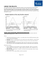
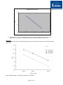
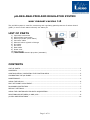
pH-REG ANALYZER AND REGULATOR SYSTEM user manual version 1.0 The pH-REG system is used for monitoring and regulating partial pressure of carbon dioxid (pCO2) in sea or fresh water indirectly via water pH. LIST OF PARTS 1) Controller instrument 2) WTW ph340i instrument 3) Sentix pH probe (fresh water) 4) Converter cable 5) Solenoid valve w/push-in fittings 6) PU tubing 7) Air stone 8) Data cable 9) Power cord 10) User manual 11) *OPTIONAL SentixH ph probe (seawater) CONTENTS LIST OF PARTS.............................................................................................................. 1 CONTENTS ................................................................................................................... 1 CONFIGURATION / OPERATING THE FUNCTION KEYS ........................................................ 2 CALIBRATING THE pH PROBE.......................................................................................... 2 MAINTENANCE .............................................................................................................. 3 USING THE RELAYS ....................................................................................................... 6 FAST SET POINT ADJUSTMENT........................................................................................ 7 PASSWORD PROTECTION ............................................................................................... 7 DEFAULT SETTINGS ....................................................................................................... 7 USING THE CONTROLLER FOR DATA ACQUISITION ........................................................... 8 RELATIONSHIP BETWEEN ph AND pCO2 ........................................................................... 8 pH-REG SPECIFICATIONS............................................................................................. 10 Page 1 of 10 SETUP Connect the WTW serial data cable to the pH 340i instrument. Then use the DB9-M12 converter cable to make the connection to the pH-REG instrument. The round black M12 connector on the converter cable should go in frontside input on the pH-REG instrument labelled IN. Then connect a pH probe to the pH 340i instrument and turn this instrument on. To power the pH-REG instrument, connect the power cord to the backside socket labelled POWER and plug it into a wall outlet or power strip. Once the pH-REG is turned on, it will start reading the analog output from the WTW pH instrument. On the backside of the pH-REG instrument there are two digital controlled relays used for control of a solenoid valve to regulate pH in the water, e.g. by injection of pure CO2 gas for hypercapnic control. CONFIGURATION / OPERATING THE FUNCTION KEYS The pH-REG is a menu-driven instrument. The front panel has three buttons for operation, e.g. two arrow buttons (Λ and V) and one OK button. Use these three buttons to scroll through the menu and accept instrument settings. For each menu there is a scrolling help text which is automatically shown in the display, this starts after five seconds if no key has been activated. Use the menu to calibrate the oxygen probe, and set relay action and level of control. Λ V OK will increase the numerical value or choose the next parameter. will decrease the numerical value or choose the previous parameter. will accept the chosen value and end the menu. To summarize, the Λ and V buttons are used to toggle betweens options. The OK button is used to accept settings and go to the next option. Press and hold the OK button for 0.5 seconds, to get the last option available. Once the entire configuration has been entered, the display will show “----”. The following two pages show the complete menu routing diagram and scrolling help texts. CALIBRATING THE pH PROBE Follow the step-wise procedure below to re-calibrate the pH probe. We recommend to calibrate the pH probe initially before using the instrument and probe for the first time. Standard two-point calibration procedure 1. Connect the pH probe to the WTW pH 340i instrument and turn on the instrument. Press CAL. 2. Place the tip of the probe in a pH 7,000 buffer solution. 3. Wait for the reading to stabilize, and press RUN/ENTER on the WTW ph340i instrument. It know shows 7,000. To save the value, press RUN/ENTER again. 4. On the pH-REG instrument press the OK button until the display reads CA.HI. Use the Λ or V button to toggle to YES, and press the OK button to accept the current probe signal for the high calibration value. 5. Press the OK button until the display reads DI.HI. and the Λ or V button to adjust the high calibration value to 7,00. Press the OK button to accept the value. Page 2 of 10 6. Then press the OK button several times, until the display reads “----“ to finish the high calibration. 7. Rinse the Sentix pH probe with distilled water. 8. Next, place the tip of the probe in an pH 4,00 buffer solution. 9. Wait for the reading to stabilize, and press RUN/ENTER on the WTW ph340i instrument. It know shows 4,000. To save the value, press RUN/ENTER again. 10. On the pH-REG instrument press the OK button until the display reads CA.LO. Use the Λ or V button to toggle to YES, and press the OK button to accept the current probe signal for the low calibration value. 11. Press the OK button until the display reads DI.LO. and the Λ or V button to adjust the low calibration value to 4,00. Press the OK button to accept the value. 12. Finally press and the OK button several times, until the display reads “----“ to finish the zero calibration. 13. Press M on the ph340i instrument to finish the calibration. For more information about the ph340i calibration see page 7 in the Operating manual. 14. Rinse the probe with distilled water. 15. Place the probe into a sample, and record the sample ph when the reading is stable. Both instruments will now show the same pH value. MAINTENANCE Between sample measurements, immerse the tip of the probe in the small cap that comes with the probe. Page 3 of 10 Page 4 of 10 Page 5 of 10 USING THE RELAYS The pH-REG instrument has two independent relays to control the activity of solenoid valves. For either of the relays choose a set point and a hysteresis value. Now decide if the relay should be activated when the signal drops below a set point (DECR), or if it should be activated when it rises above (INCR), e.g. for hypercapnic control the relay should act on a increasing (INCR) signal, since pH values will tend to climb as pCO2 values moves toward equilibrium with atmospheric values. Example – how to avoid high pCO2 despite high fish respiration rates Follow the below procedure to keep pH at 6,00 in a recirculated fish tank stocked with fish producing CO2 at high rates. Set up 1. Connect the solenoid valve to relay 1 on the back side of the pH-REG instrument (relay 2 is not used in this example). 2. Connect a supply of compressed air to the solenoid valve input labeled P, using the blue PU tubing. 3. Connect a suitable length of blue PU tubing to the large air stone and to the solenoid valve output labeled A. 4. Then place the air stone in the aquarium. Now, when the relay turns on, the solenoid valve will open, and air will bubble through the water to lower pCO2 (and increase pH). Instrument settings 5. Press the OK button several times until the display reads REL1. Wait for one second, and the display now reads SET, or toggle using arrow buttons until it reads SET, and then press OK. 6. Now use the Λ or V buttons to increase or decrease the set point value. Set it to 6,00, and then press OK. 7. Set the action of the relay to DECR, and then press OK. Page 6 of 10 8. Now enter the hysteresis value. Use arrow buttons to set the value to 0,02, and then press OK. 9. Press OK several times, until the display reads “----“ to finish. Relay 1 will be activated every time pH drops below 6,00, allowing air to pass the valve and into the water via the air stone. This will cause pH of the water to increase, and as it reaches 6,02 the relay will close. Once pH drop below 6,00 again due to fish respiration, the relay 1 will automatically open once more in this way keeping pH at 6,00 - 6,02 at all times. FAST SET POINT ADJUSTMENT It is possible to quickly change set point values without having to scroll through the whole instrument menu. With the instrument turned on, press the Λ button once. Now choose relay 1 (or 2), and press the OK button. Then change the set point value using the arrow buttons. Finish by pressing the OK button. Test relay functions, by pressing both arrow buttons simultaneously. The LED diode will toggle its state. When done, press and hold the OK button until the display reads “----”. PASSWORD PROTECTION Using a password will stop access to some of the menu and parameters. There are two levels of password protection. Passwords between 0000-4999 will allow access to the fast set point adjustment and relay test. (Using this password stops access to all other parts of the menu). Passwords between 5000-9999 stop access to all parts of the menu, fast set point and relay test. (Current set point is still shown). By using the master password 2008, all configuration menus are available. If you want to enable password protection, press the OK button several times, until the display reads E.PAS. Use an arrow button to choose YES, and then press OK. Now set the password using the arrow buttons, and press OK when done. If you want to disable password protection, go to the menu option E.PAS. again and set it to NO. Finish by pressing the OK button. DEFAULT SETTINGS The pH-REG instrument is delivered with the following default settings: INPUT TYPE: DECIMAL POINT: DISPLAY LOW VALUE: DISPLAY HIGH VALUE: RELAY 1 UNITS: ON.DE (REL1 and REL2) OF.DE (REL1 and REL2) ANALOG OUTPUT: RESP POTMETER 11.11 4.00 7.00 DISP 0 0 4-20 (converted into a 0-5V instrument output) 0.4 Page 7 of 10 USING THE CONTROLLER FOR DATA ACQUISITION The instrument produces a 0-5 Volts analog output signal for data acquisition purposes. Connect the data cable to the socket marked Out on the backside of the pH-REG instrument. Connector pin 1 is positive (+), connector pin 4 is 0 (zero). The low instrument value (DI.LO) corresponds to a 0 V output, and the high value (DI.HI) corresponds to a 5 V output. This means, that the gain becomes HI value/5 V. With the default values the gain is then 1,4 pH/V, e.g. if the output voltage is 4 V, the calculated pH value is 5,6. RELATIONSHIP BETWEEN pH AND pCO2 From the Henderson–Hasselbalch equation it is known that: pH log pCO2 K , where K is a parameter including effects of temperature, salinity, alkalinity. To use this formula it is therefore important to keep K constant. If K is kept constant, the relationship between pCO2 and pH is obtained by measuring pH in water equilibrated with different CO2 partial pressures, e.g. either from a gas mixing pump (Radiometer, Wösthoff), thermal mass flow system (Brooks Instruments), or from pressure bottles with special gas mixtures from suppliers of lab gasses. Now pCO2 values can be determined from a linear curve in a semi log plot (log pCO2 vs. pH), and controlled automatically to set-point levels. Two-point calibration example: using atmospheric air and 3% CO2 gas 1. Pour sample water in two containers. Make sure to use water of the same quality (ie. buffer capacity) as the water used for the experiments. 2. Bubble one of two samples with atmospheric air and the second water sample with 3% CO2 gas for 10 minutes to alow time for equilibration. Use stirrers to mix samples. 3. Measure pH values in both samples. In this example we measure pH 7,000 in the sample bubbled with atmospheric air and pH 5,000 in the 3% CO2 sample. 4. Plot both pH values against log pCO2 values in a semi log plot and draw a straight line between the two points. Page 8 of 10 Relastionship pH vs. pCO2 10 pCO2 1 0,1 0,01 4 5 6 7 8 pH 5. Now this line gives the relationship between pH and pCO2 for the water in the aquarium, e.g. if pH is measured to 5,50 it means that pCO2 equals 1%. Example: The plot below shows the relationship between pH and pCO2 measured in Denmark 2008 (Aarhus). Dept. Zoophysiology, University of Aarhus, Denmark Page 9 of 10 pH-REG SPECIFICATIONS Supply voltage (universal): Internal consumption: Max. consumption: Isolation voltage (test / operation): Signal- / noise ratio: Response time, programmable: Calibration temperature: Accuracy: Temperature Coefficient: EMC immunity influence: Potentiometer input, min: Potentiometer input, max: Relay function: Hysteresis, in % / display counts: On and Off delay: Sensor error detection: Max. voltage: Max. current: Max. AC power: Max. current at 24 VDC: 21.6-253 VAC, 50-60 Hz or 19.2-300 VDC 3.2 W 3.5 W 2.3 kVAC / 250 VAC Min. 60 dB (0-100 kHz) 0.4-60 s 20-28°C ≤±0.1% of reading ≤±0.01% of reading/ °C ≤±0.5% of reading 10 Ω 100 kΩ Setpoint 0.1-25% / 1-2999 0-3600 s Make / Break / Hold 250 VRMS 2 A / AC 500 VA 1A IMPORTANT: DO NOT connect relays to >500W equipment (max 2 A, 250 V). Marine approval Det Norske Veritas, Ships & Offshore Standard for Certification No. 2.4 Observed authority requirements: Standard: EMC 2004/108/EC Emission and immunity EN 61326 LVD 73/23/EEC EN 61010-1 UL, Standard for Safety UL 508 Page 10 of 10